Tools for medical manufacturing, aerospace and optics
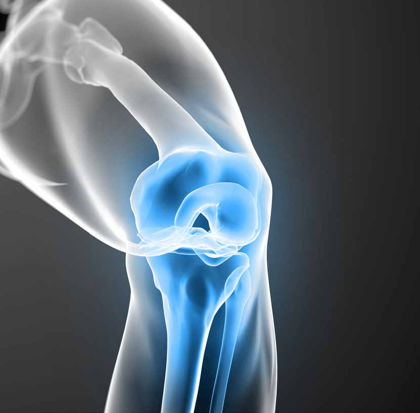
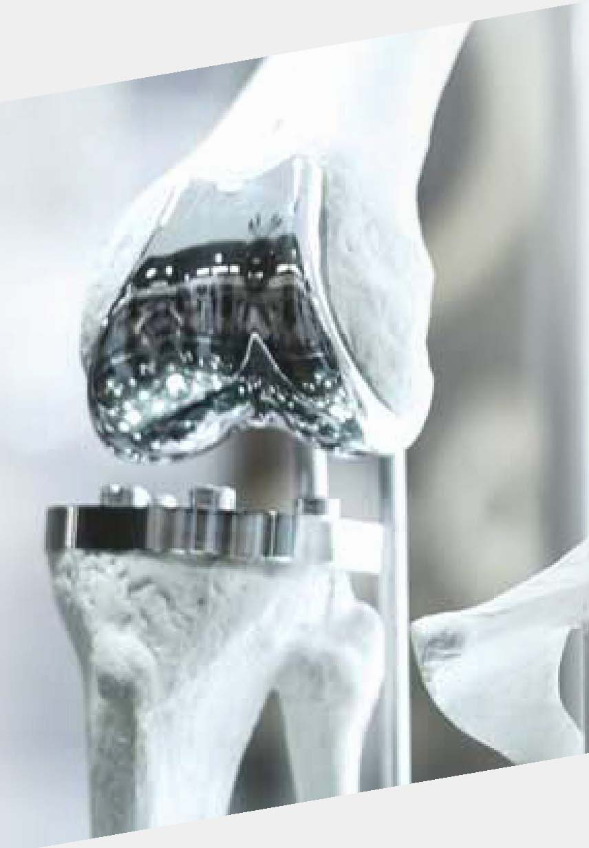
EHWA combines diamond and CBN grinding tools with rotary dressers and rotating tools for demanding component manufacturing. The range covers artificial knee joints, medical wire and needles, contact and intraocular lenses, spectacle lenses, turbine components and lightweight parts. Metal bonds for automotive glass edges are also included. Tool selection is matched to material, component geometry, machine and the required surface.


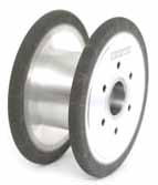
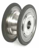
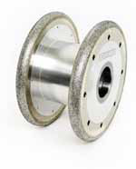
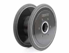
Knee-joint grinding: four body variants
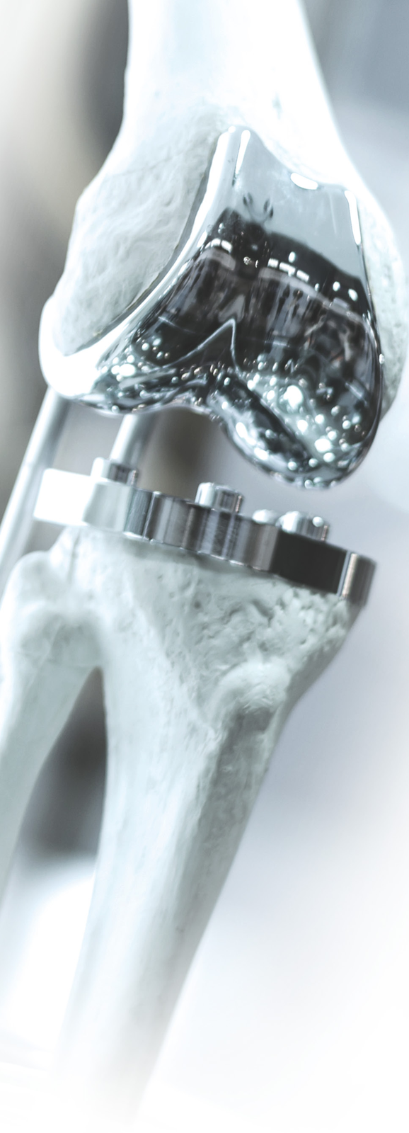
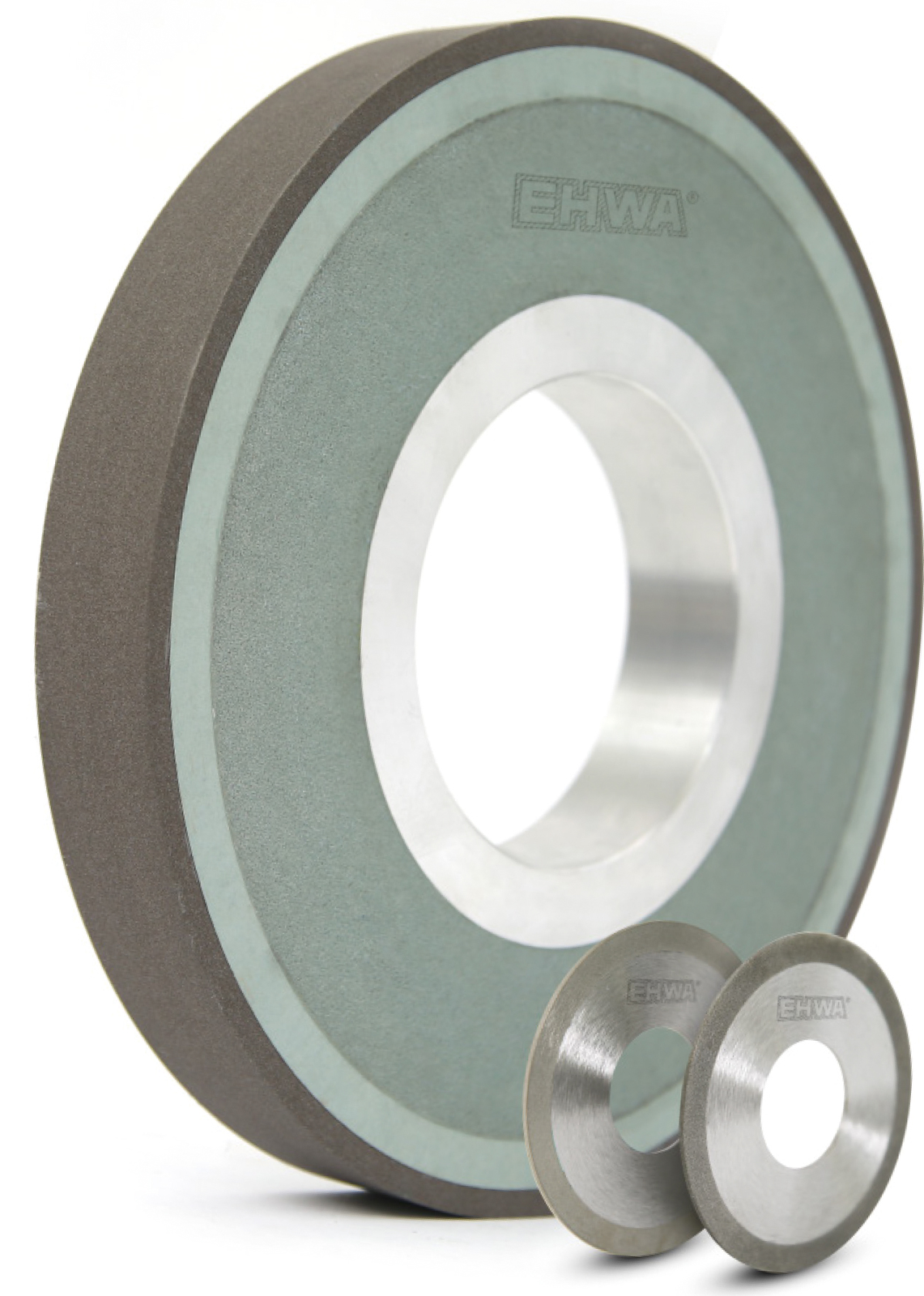
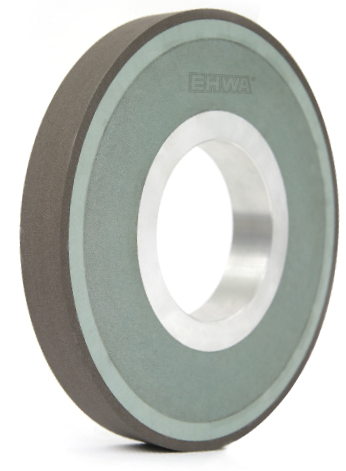
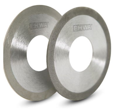
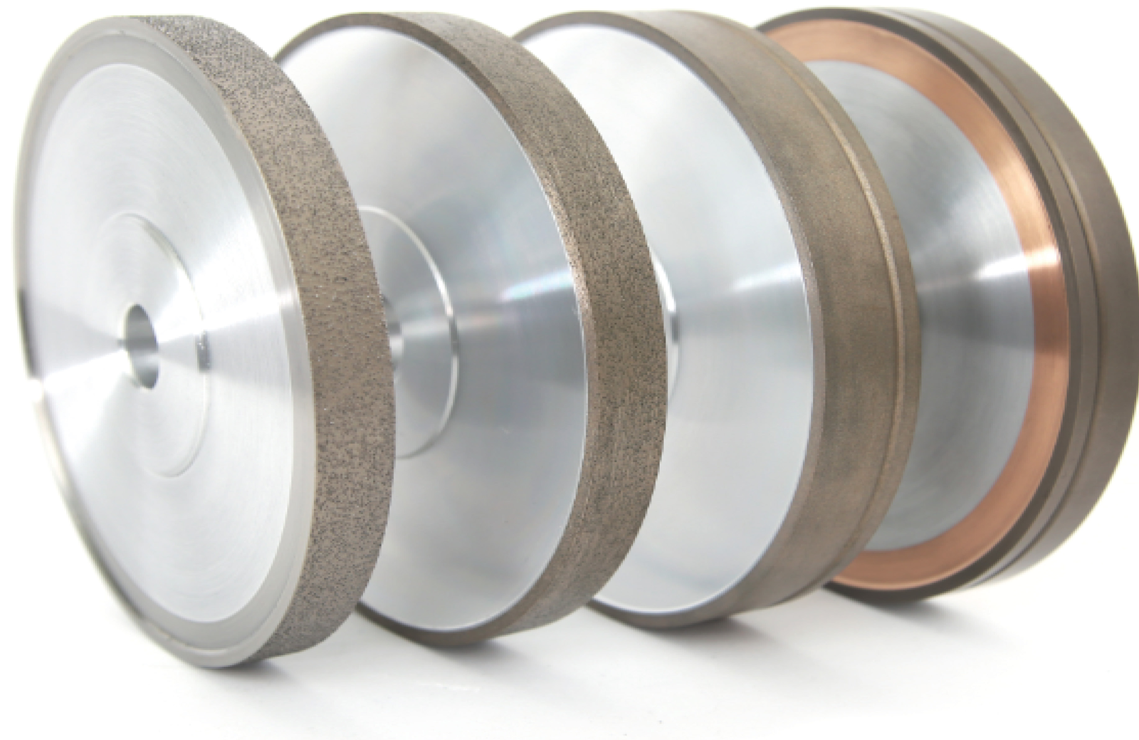
For grinding artificial knee-joint components, the range shows vitrified tools with CFRP, aluminium-alloy or steel/aluminium bodies, and electroplated tools with steel/aluminium bodies. These variants support tool designs matched to the component profile and machine mounting. CFRP here identifies the wheel body; bond type is listed separately.
| Bond | Body |
|---|---|
| Vitrified | CFRP |
| Vitrified | Aluminium alloy |
| Vitrified | Steel + aluminium |
| Electroplated | Steel + aluminium |
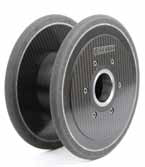
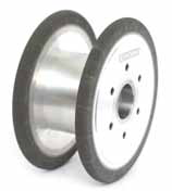
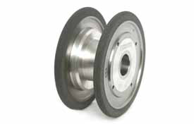
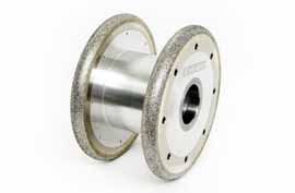
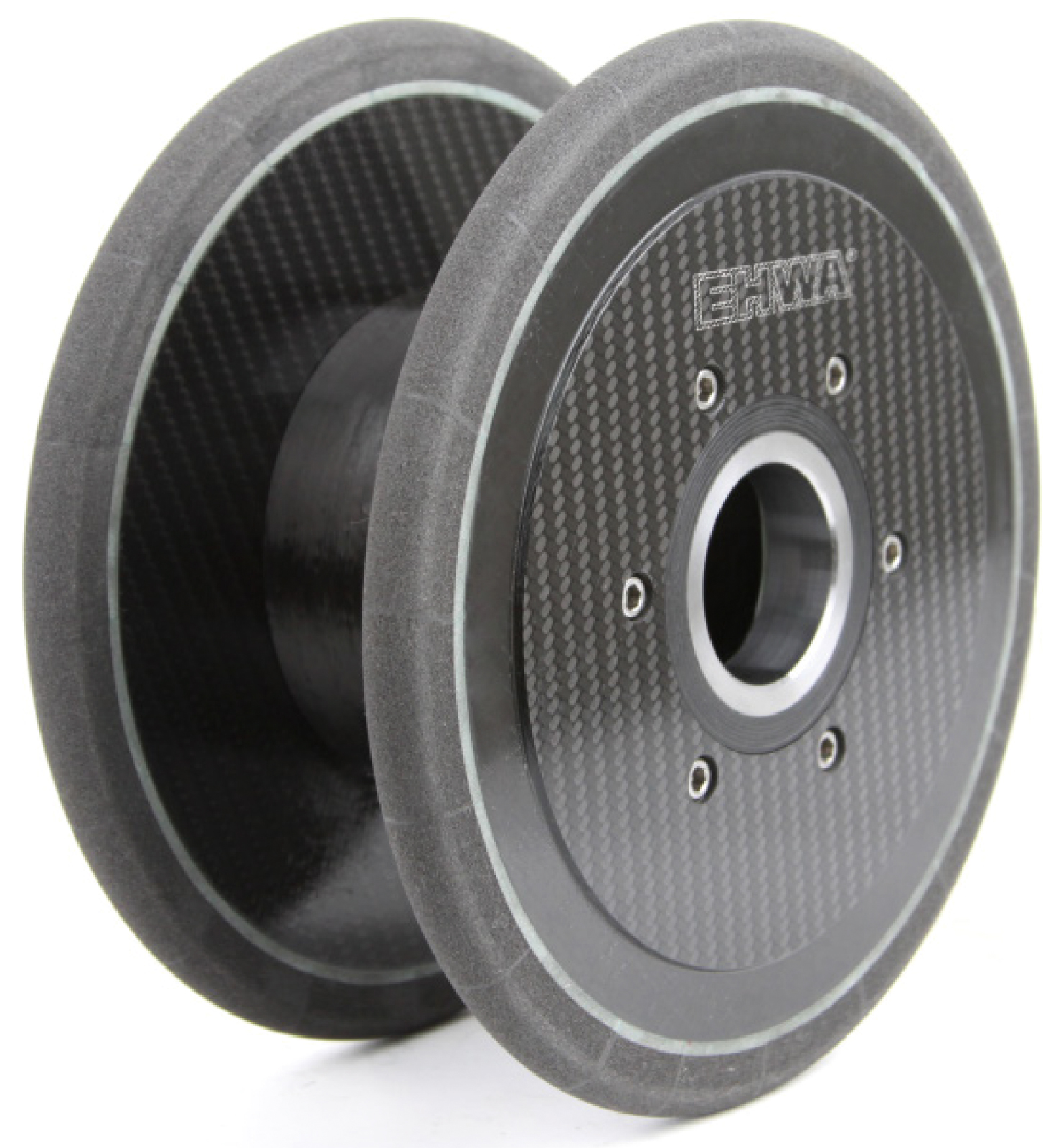

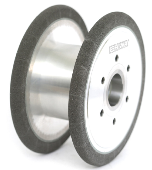
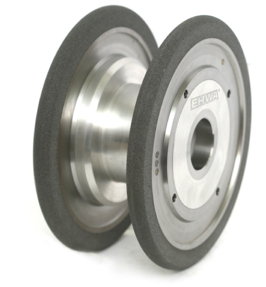
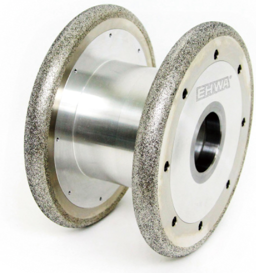
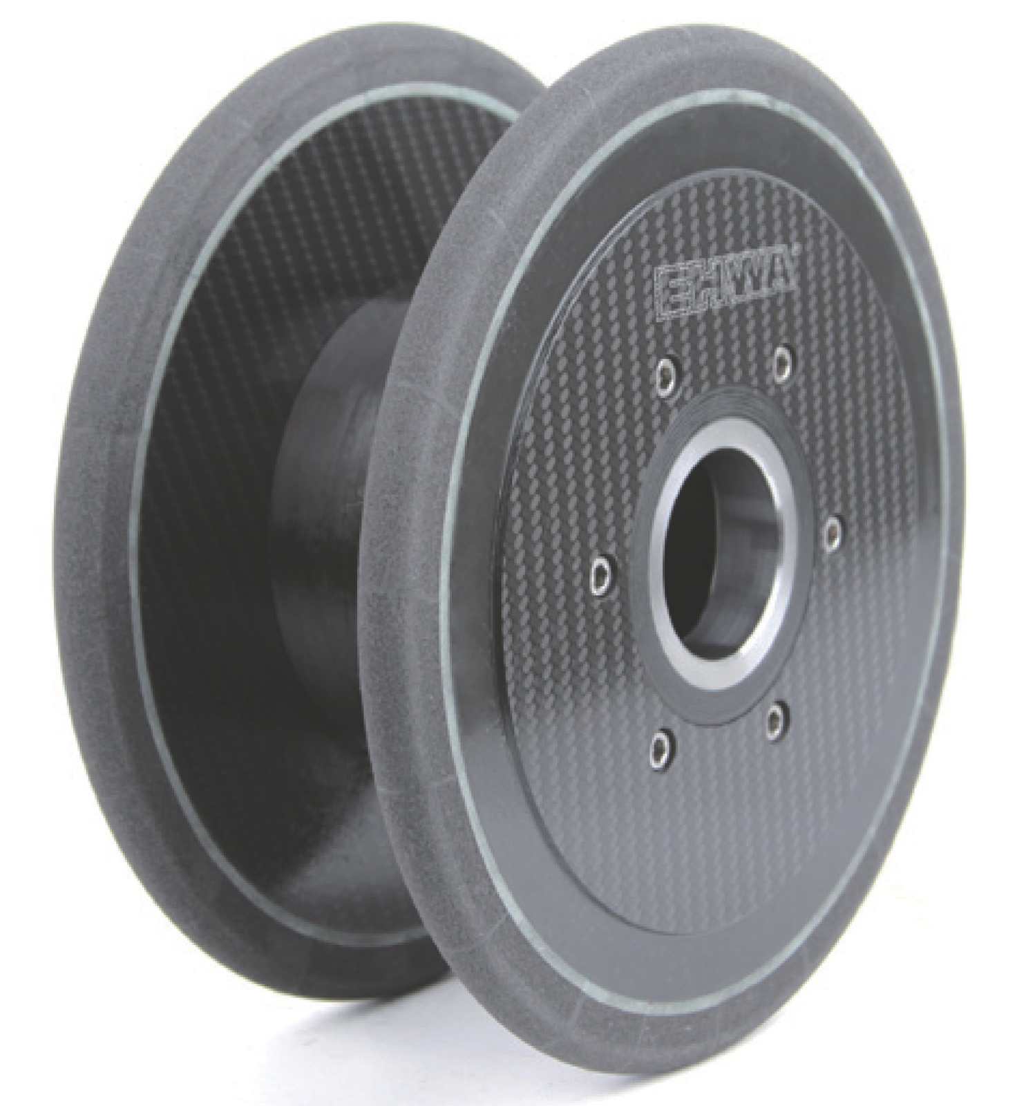
Grinding wheels and diamond rotary dressers for knee components
The knee-joint application targets high stock removal, well-balanced tools for high-speed operation, longer dressing intervals and wheel life, and strong grinding performance and surface quality. Diamond rotary dressers are matched to profiling these grinding tools. The following standard designations agree between the older medical document and the later application collection. A dash means that no specification is entered in the source.
| Tool | Wheel size / designation | Specification |
|---|---|---|
| Vitrified CBN | VB-14F1, 250D-120T-20X-16U-8R-51H | B252L150VBW |
| Vitrified CBN | VB-14F1, 240D-120T-20X-18U-10R-51H | B252L150VBW |
| Diamond rotary dresser | ROTARY-RP 98D-25T-10R-25H | — |
| Diamond rotary dresser | ROTARY-IP1, 175D-2R-22T-52H | — |
| Electroplated CBN | EB-1FF1, 200D-120T-20U-12R-51H | B427 |
| Electroplated CBN | EB-1FF1, 200D-120T-12U-6R-51H | B252,B301 |
| Electroplated CBN | EB-1FF1, 160.45D-16T-8R-20H B427 | B427 |
Wire grinding: two application programmes
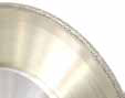
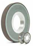
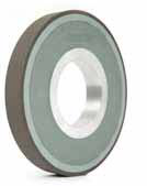
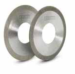
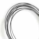
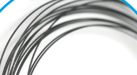
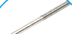
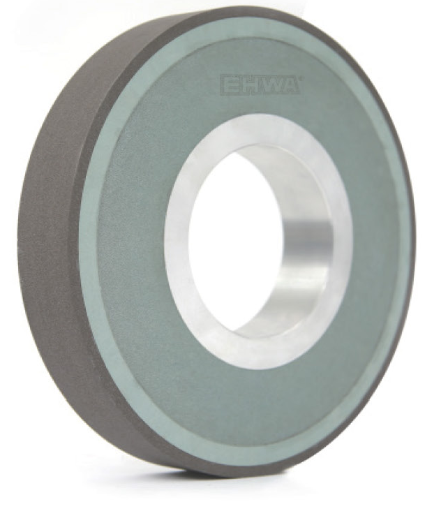
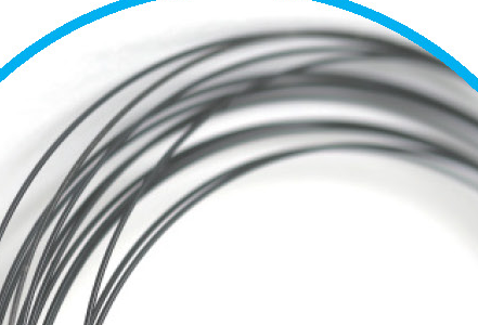
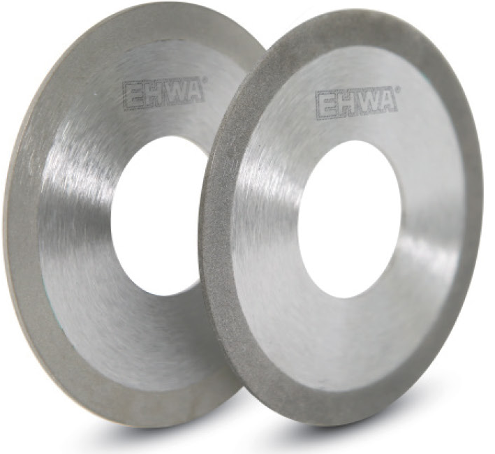
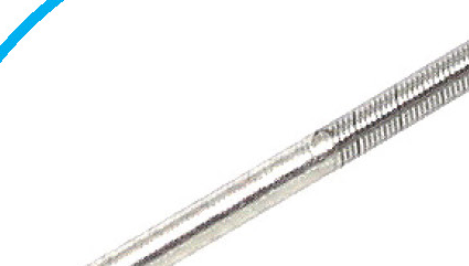
The first programme combines low grinding pressure and free-cutting behaviour with high wire-surface quality, long wheel life, economical machining and good balance. The second programme emphasises a straight face with a sharp edge, low cutting force, free-cutting wheels and good wire surfaces. The illustrations show the two programmes with coiled and straight wire workpieces. Tool geometry and the process are matched to the particular wire.




Electrochemical needle grinding (ECG)
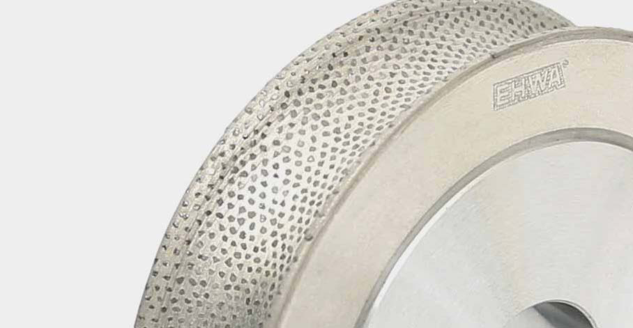
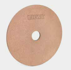
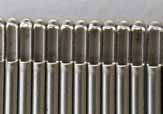
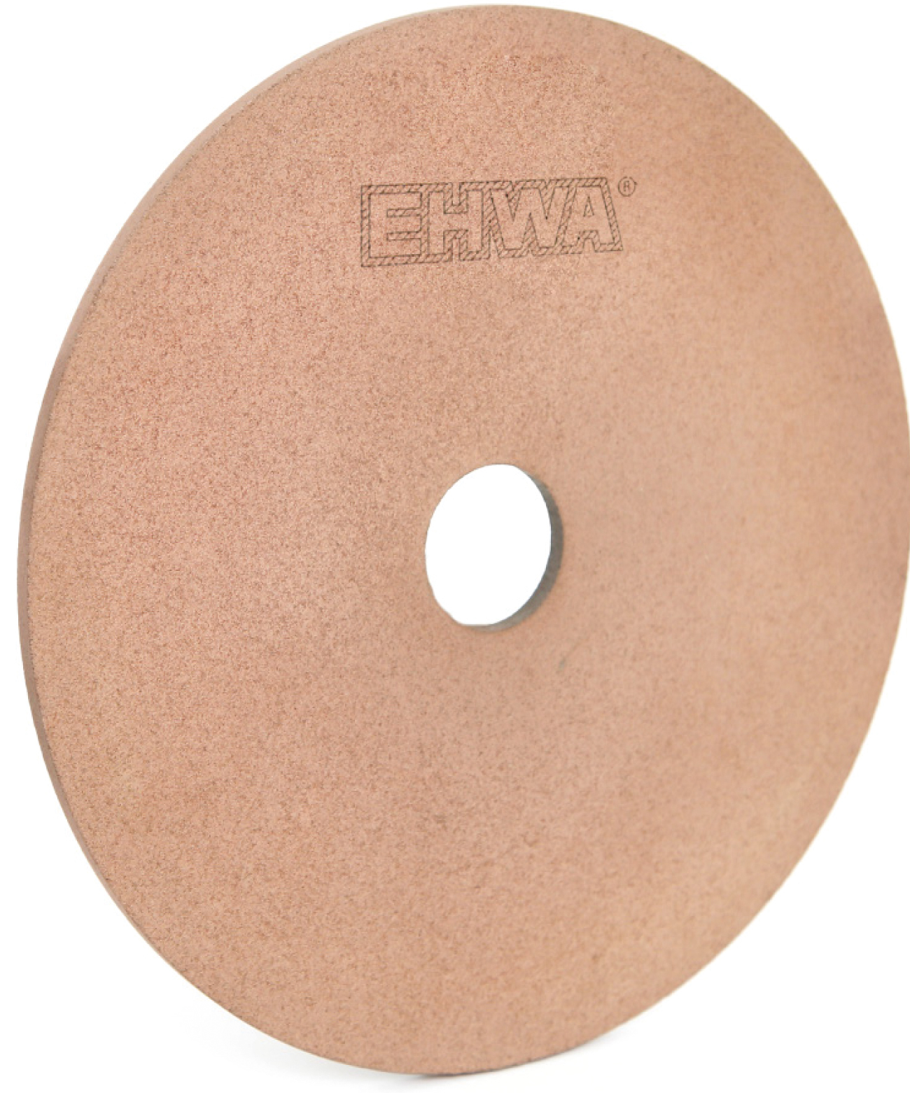
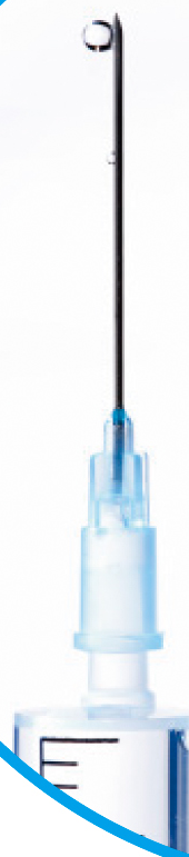
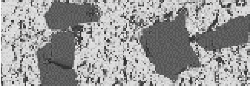
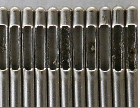
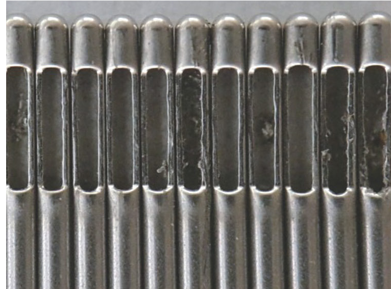
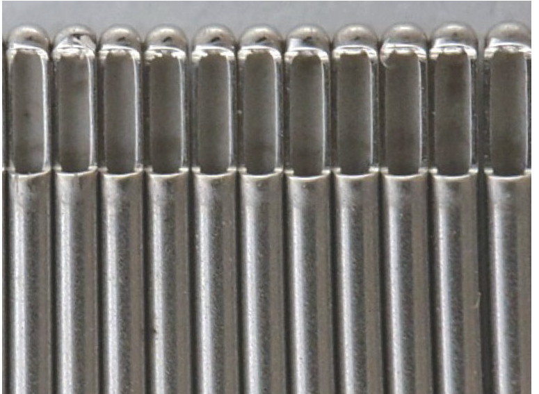
ECG combines abrasive grinding with electrochemical material removal. EHWA shows tools for medical needles made from SUS or SUS304. The range targets low tool or per-part costs, high stock removal, strong surface quality with burr-free needle tips, and consistent grinding performance. The comparison images show burrs after conventional grinding and burr-free tips in the illustrated ECG example; results are matched to material and process conditions. The micrograph shows the grinding-wheel bond structure.
| Type | Specification |
|---|---|
| MB-1A1 | 204D-3T ~ 15T |
| MB-3A1 | 204D-1U~2.9U |





Diamond tools for contact lenses
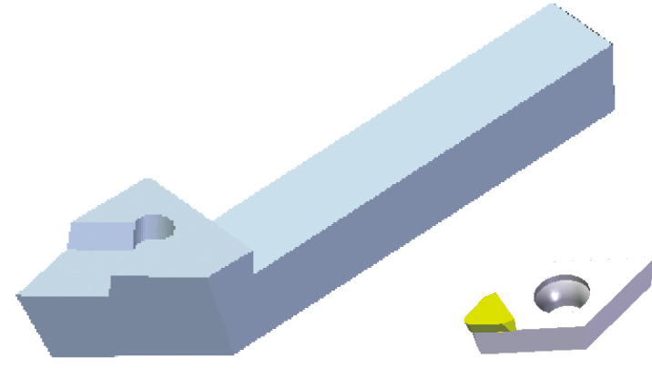
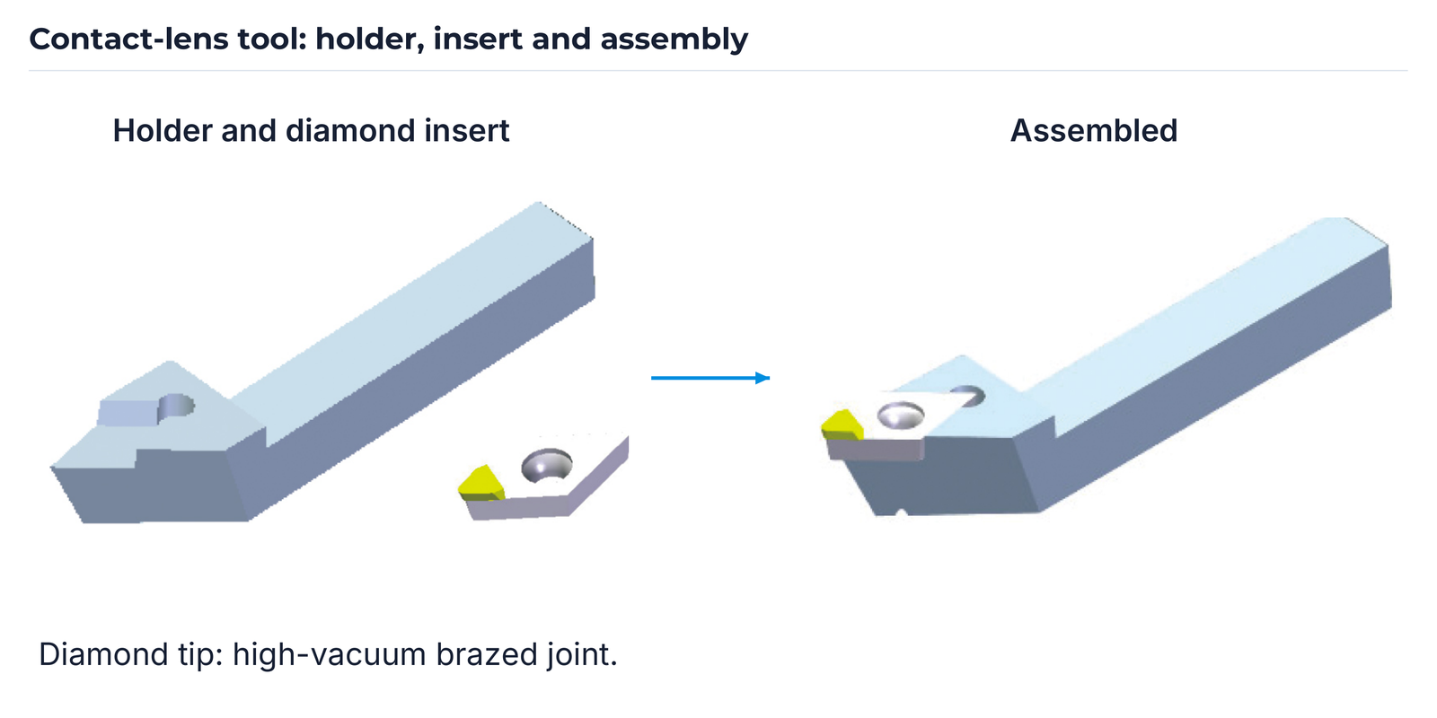
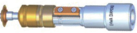
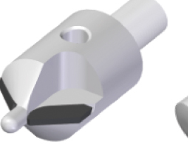
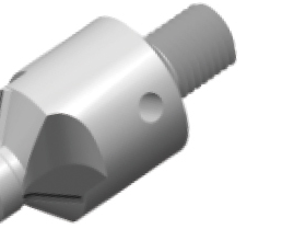
Contact-lens tools with a high-vacuum-brazed diamond tip combine consistent machining quality with long tool life. EHWA describes the cutting edge as free of chipping under 1000× microscopic inspection. The illustration shows holder and insert before assembly and the assembled tool. Cutting-edge quality is checked on the particular tool.


Tools for intraocular lenses (IOL)
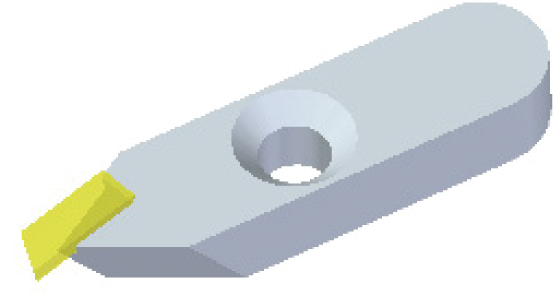
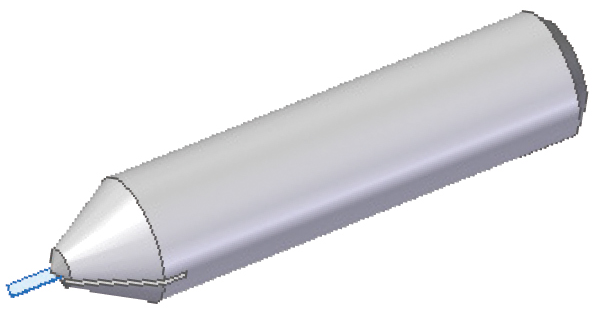
The IOL range shows flat and cylindrical tool designs. Both belong to the high-vacuum-brazed diamond-tip tool range. EHWA lists consistent machining quality, high dimensional accuracy and a cutting edge free of chipping under 1000× microscopic inspection. These statements concern tool and manufacturing quality.
Cutters for spectacle lenses
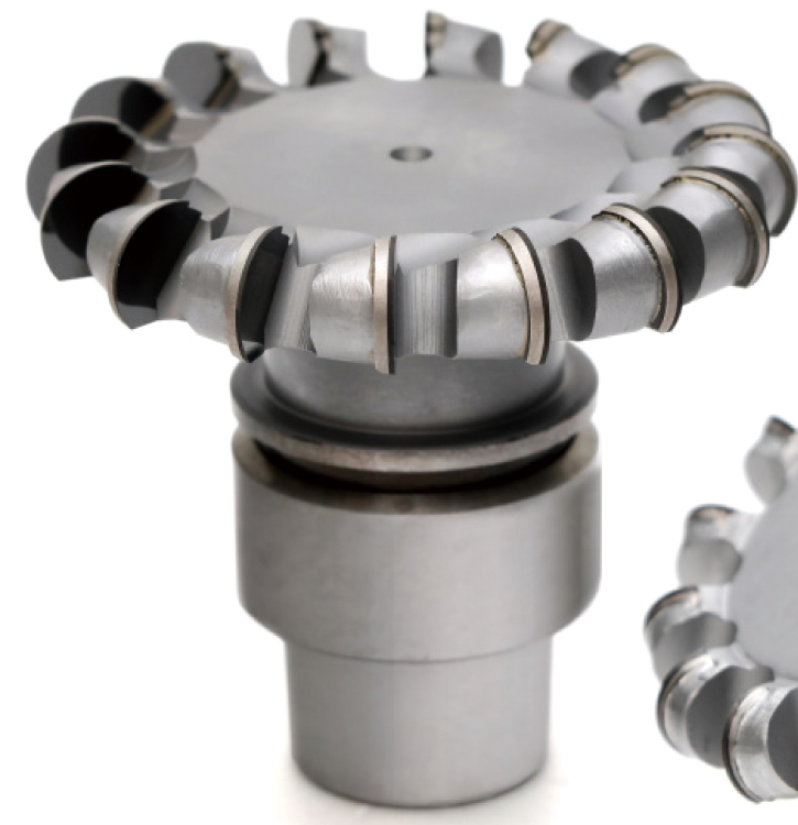
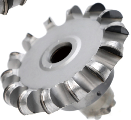
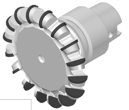
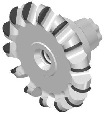
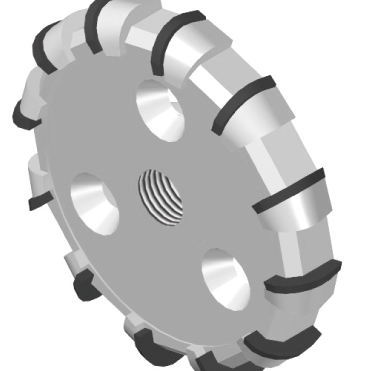
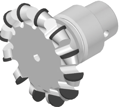
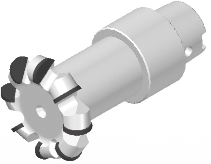
EHWA offers cutters for lens materials such as polycarbonate, CR-39 and high-index materials. The range combines strong cutting performance with long tool life and good surface finish. Designs differ in cutting-edge count and mounting. The 16Z and 15Z versions are described for higher feed. CW/CCW identifies the stated clockwise/counterclockwise designs; no rotation direction is stated for 14Z.
| Designation | Cutting edges | Design / feature |
|---|---|---|
| 66D-16Z-HSK32E (C) | 16Z | Higher feed; CW/CCW |
| 66D-14Z-flw | 14Z | 14 cutting edges |
| 66D-15Z-HSK32E(C) | 15Z | Higher feed; CW/CCW |
| 67.5D-12Z-disc | 12Z | CW/CCW |
| 66D-12Z-HSK32E(C) | 12Z | CW/CCW |
| 45D-8Z-HSK32C | 8Z | CW/CCW |

Grinding wheels for optical lenses
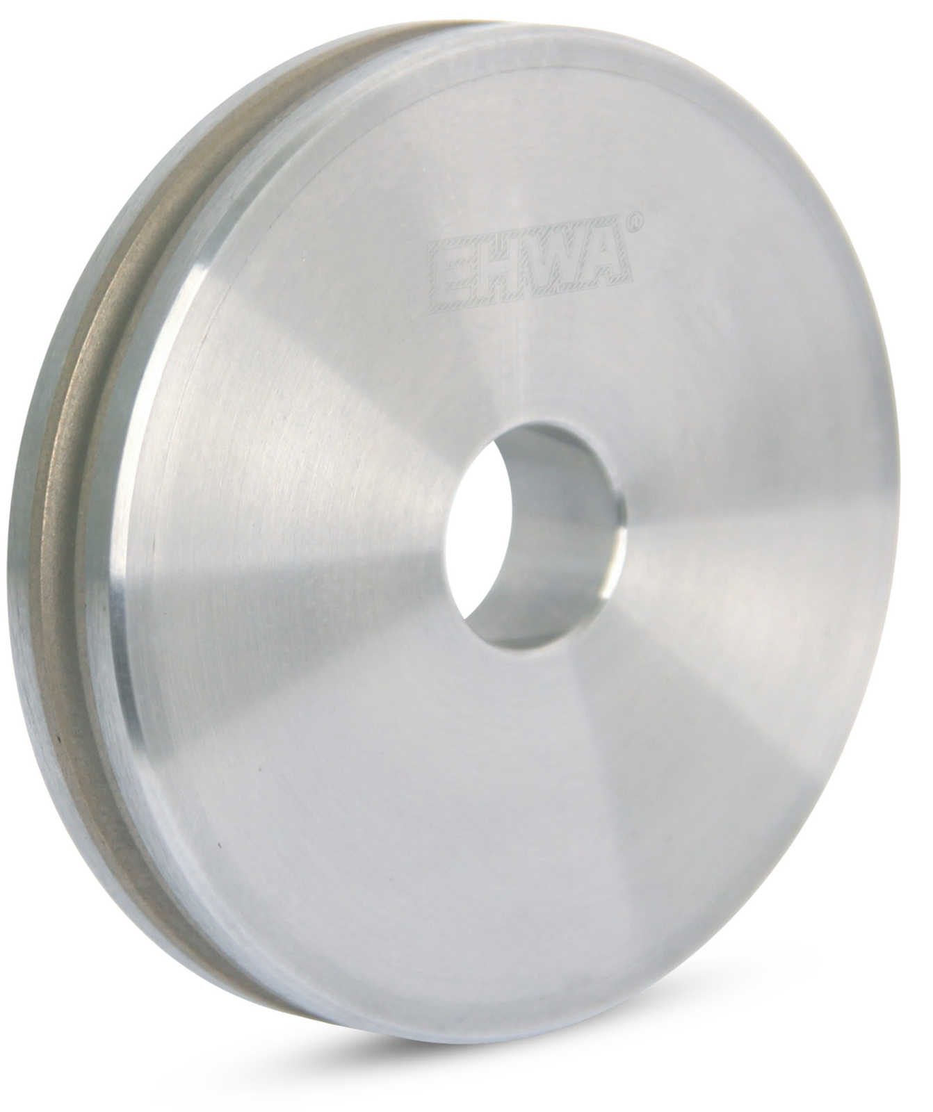
The grinding range covers glass, plastics, polycarbonate, high-index materials and CR39. Machining stages include roughing, finishing, polishing and grooving. The functional diagram associates the three wheel sections with roughing using BSL/metal bond, finishing using metal bond and polishing using metal bond. GL and PL are retained as application designations. The dimensions use the source document’s D designation.
| Application | Type | Grit size | Dimension |
|---|---|---|---|
| Roughing (GL) | MD-1A1 | #80 | 100D, 155D |
| Roughing (PL) | BSL | #60 | 100D, 155D |
| Finishing | MD-1EE6Y | #400 | 60D, 100D, 155D |
| Polishing | MD-1EE6Y | #3000 | 60D, 100D, 155D |
| Grooving | MD-14F1 | #270 | 20D |



BSL: slot and straight designs
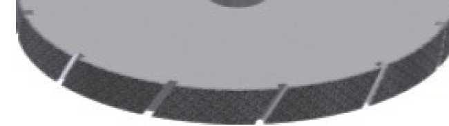
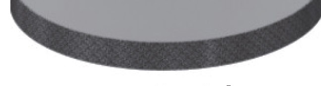
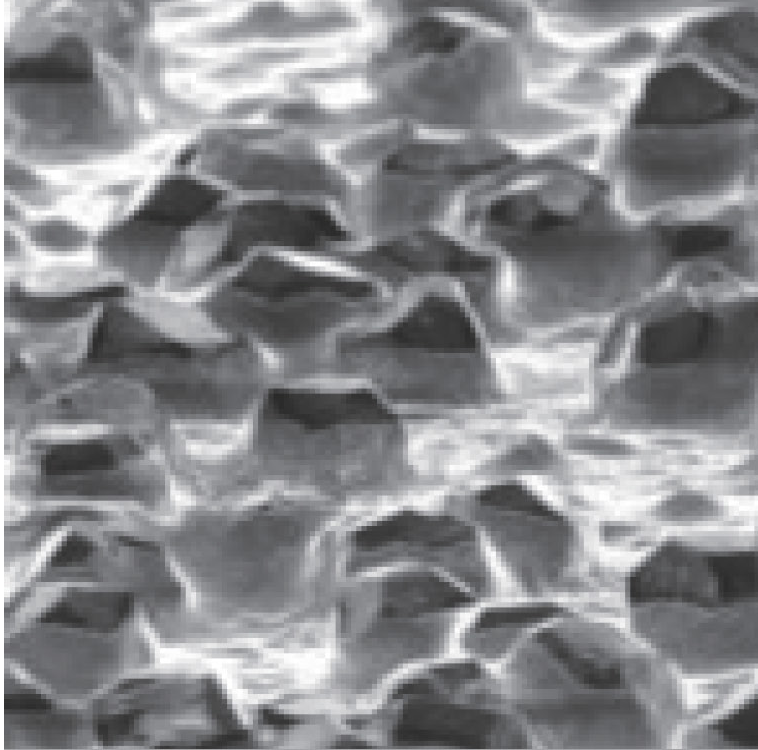
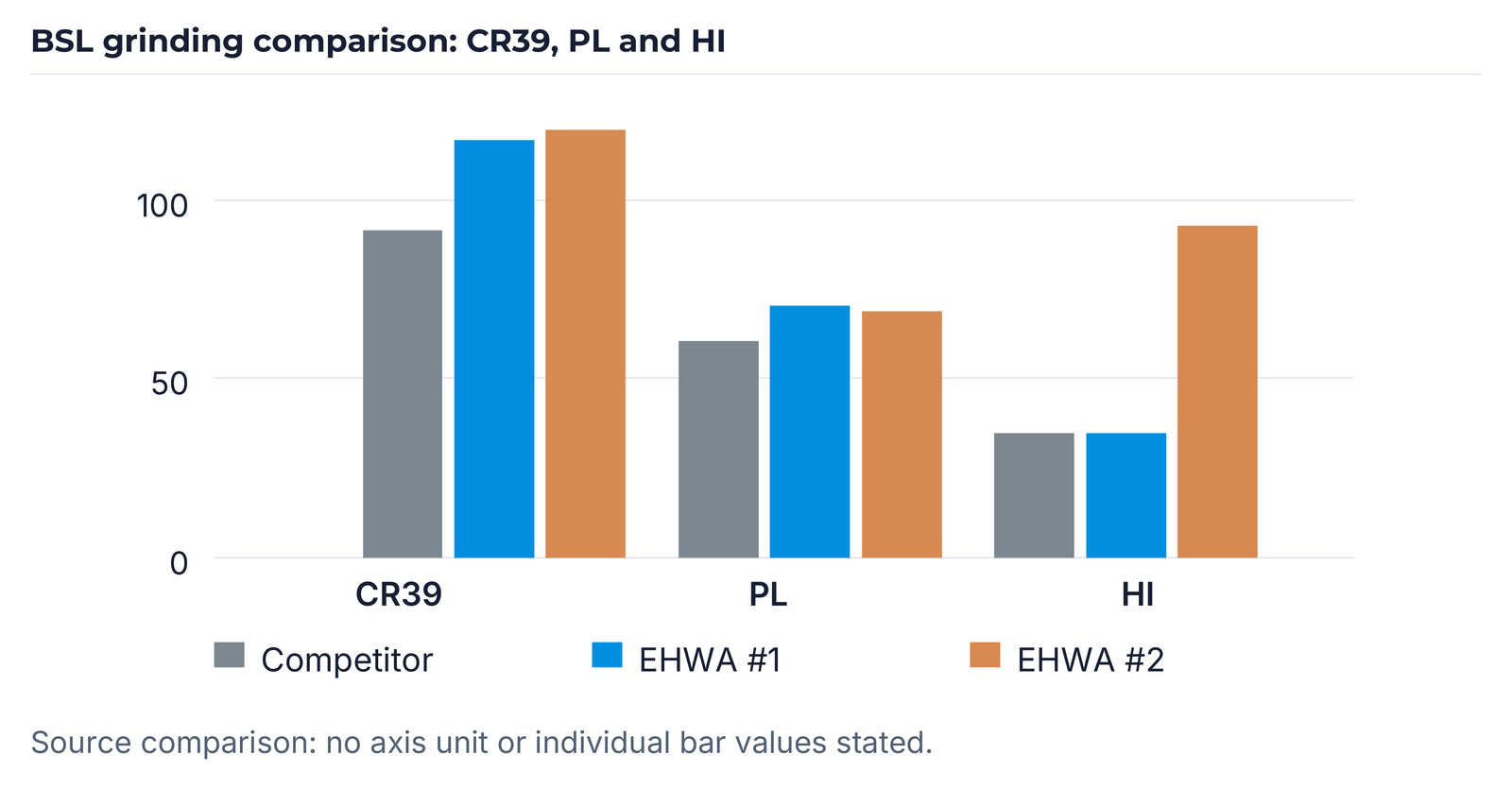
The comparison shows the competitor, EHWA #1 and EHWA #2 for CR39, PL and HI. EHWA #1 is shown as the slot design and EHWA #2 as the straight design. The micrograph complements the wheel surface. The chart preserves the printed 0 / 50 / 100 axis and bar geometry; the source states no axis unit and no individual bar labels.
Metal bonds for automotive glass edges
Metal-bonded diamond wheels are used for pencil edging and seaming of automotive window glass. Bond selection is matched to glass type, grit size and the required edge quality. The B and C bond series are listed for D54~D35. The table category “High Quality G (D35~)” is retained as a source designation. Marks reproduce the stated classifications; a dash replaces an empty source field.
| Bond | General (D54 or D46) | High Quality G (D35~) | Remark |
|---|---|---|---|
| MB21 | — | ● | Excellent grinding performance |
| MC6 | ● | ● | General bond |
| MC9 | ● | — | Longer tool life and good quality |
| MC11 | ● | — | Longest tool life in the stated range |
G bond series and Eagle microstructure
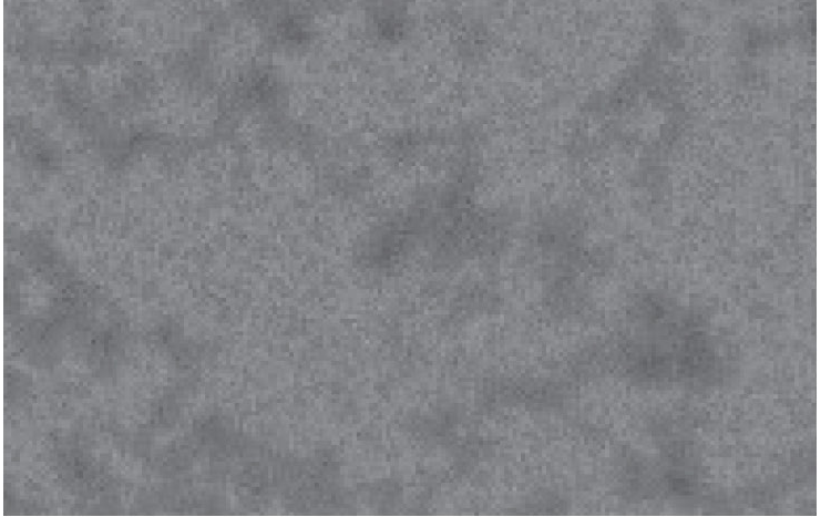
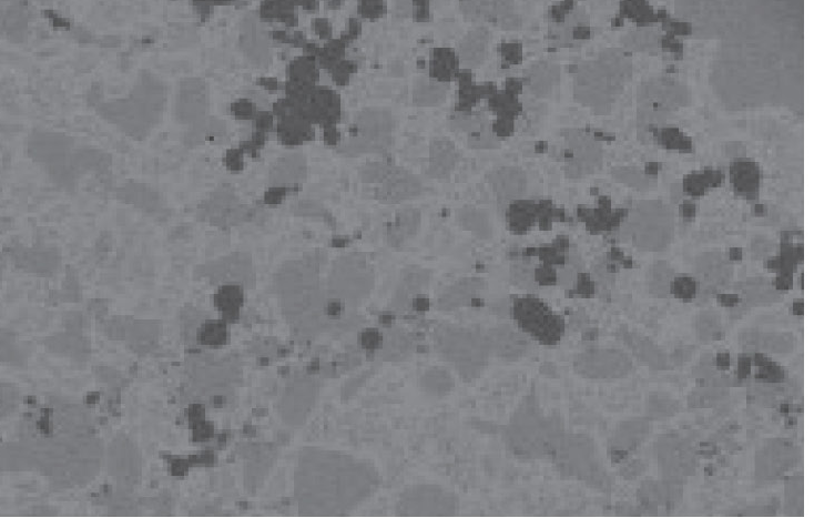
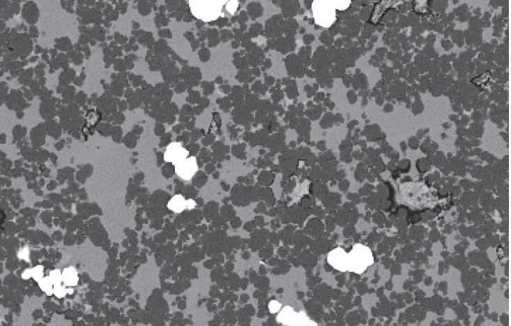
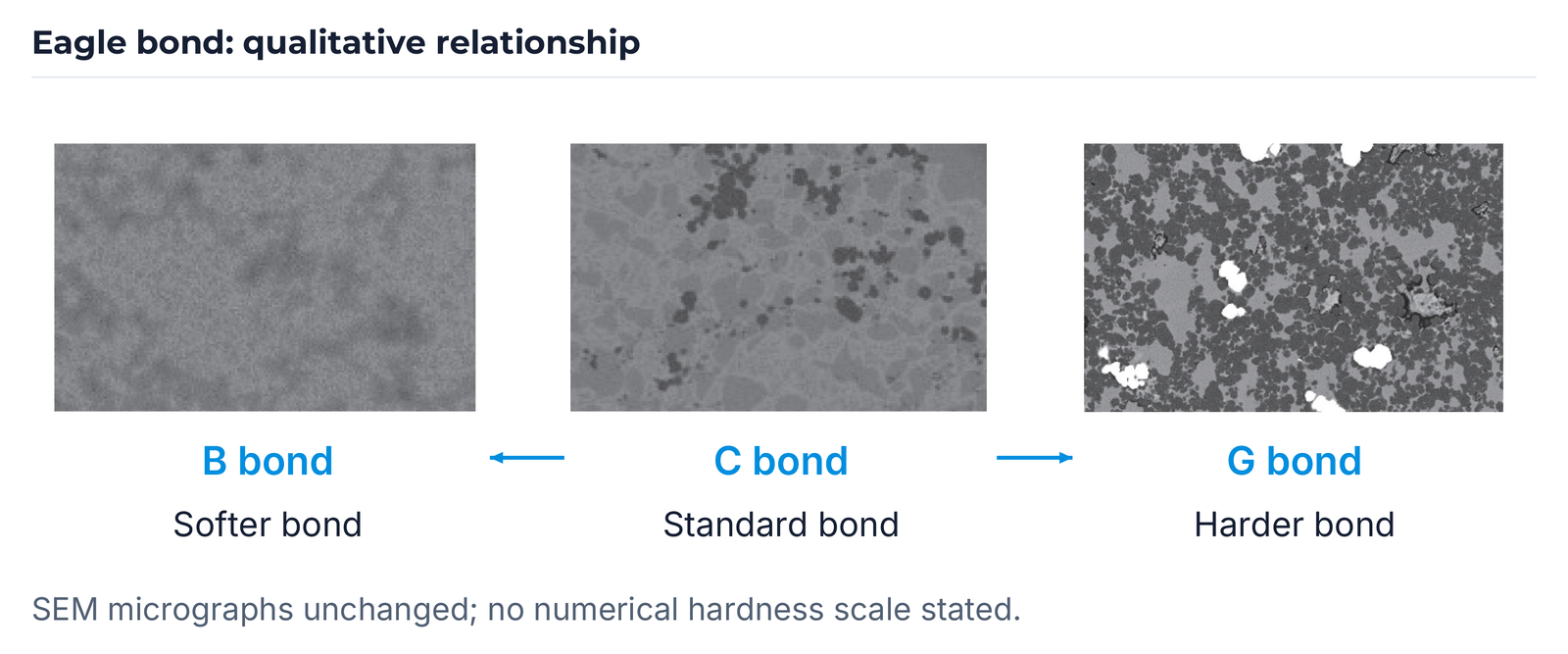
The G bond series is listed for D91~D76 and distinguishes tempered glass from laminated glass. The SEM images show the Eagle B, C and G bonds: B is presented as softer, C as the standard bond and G as harder. This is a qualitative relationship without added hardness values.
| Bond | Tempered glass | Laminated glass | Remark |
|---|---|---|---|
| MG7 | — | ● | Excellent grinding performance |
| MG16C | ● | ● | — |
| MG21N | ● | — | Longer tool life and good quality |
| MG72 | ● | — | Longer tool life and high grinding speed |
Rotary dressers for turbine blades
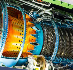
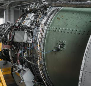
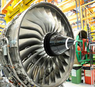
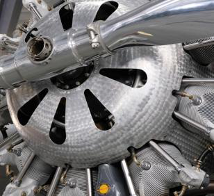
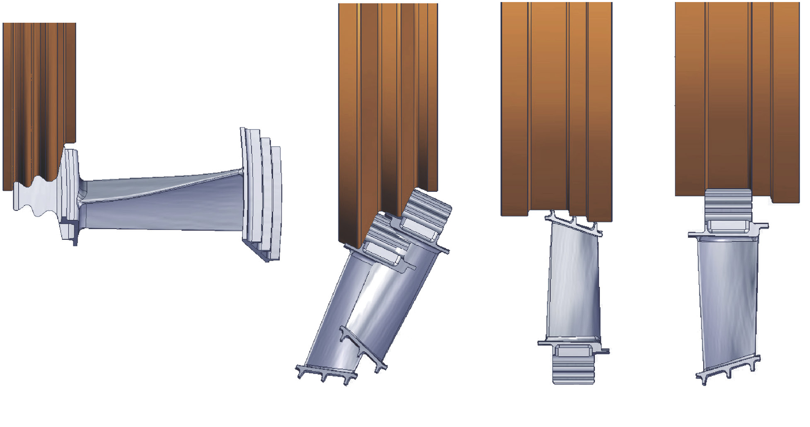
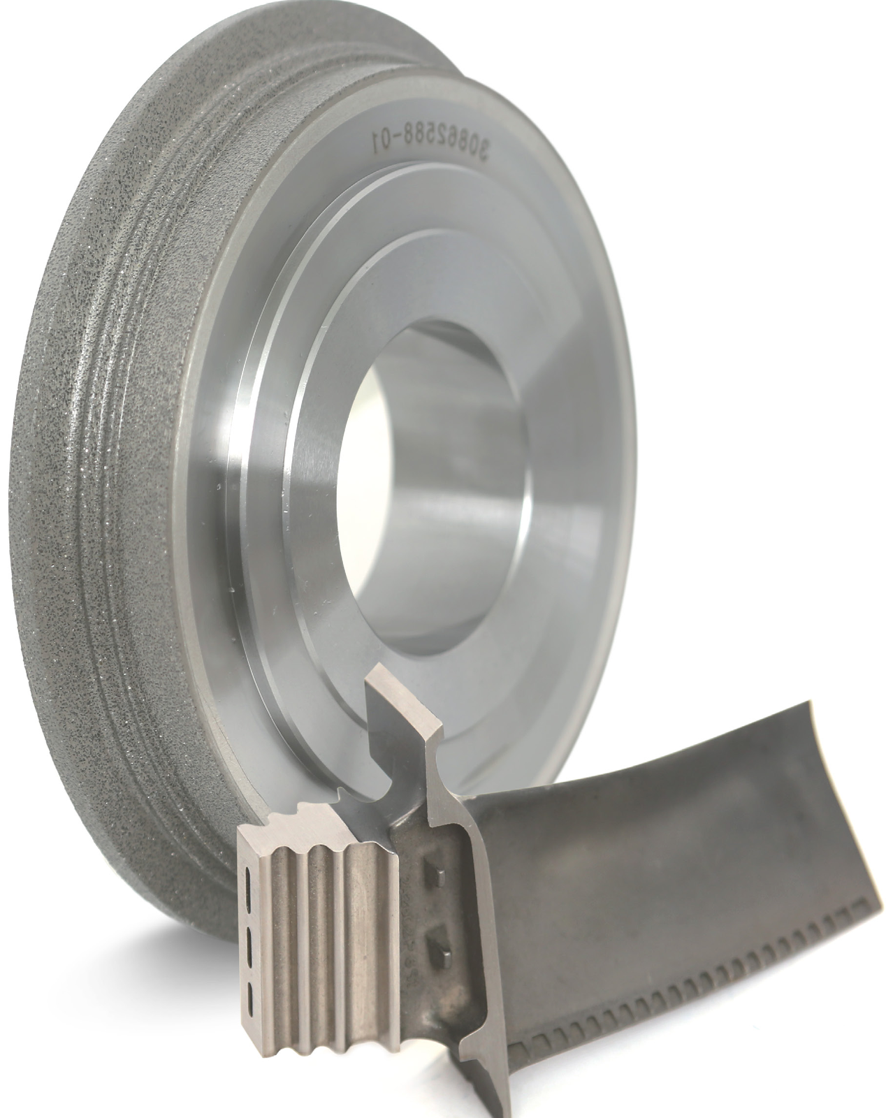
Workpiece-specific rotary-dresser designs combine high tool precision with long tool life. EHWA describes stable dressing performance in creep-feed grinding. Four contact positions show adaptation to different blade profiles. The dresser-and-blade illustration and aircraft-engine photograph show the application.

Carbide end mills and drills
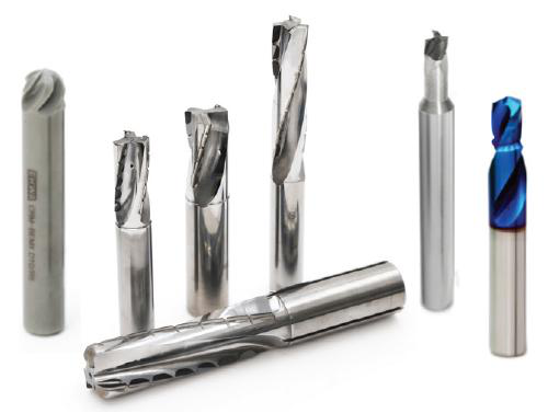
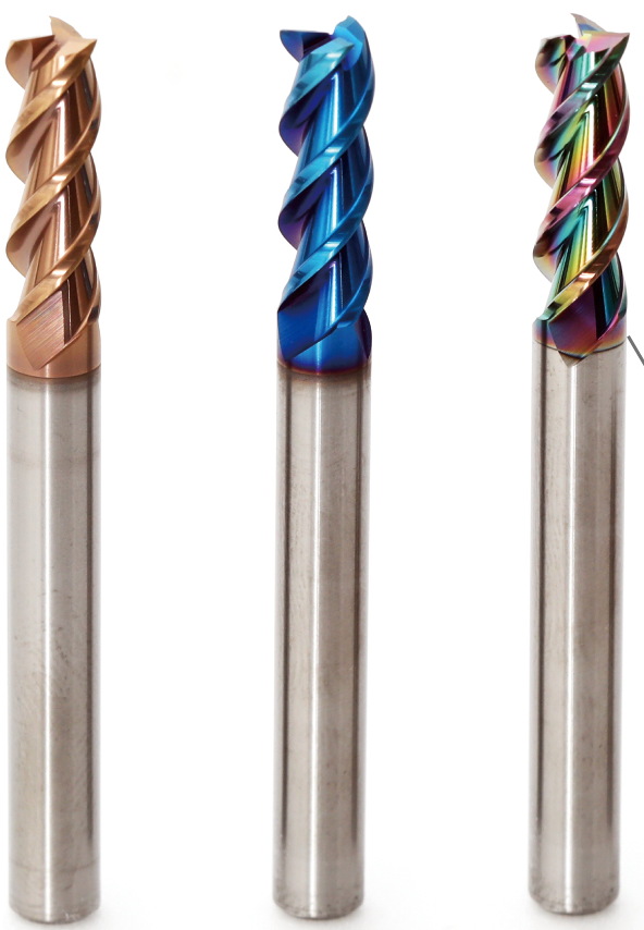
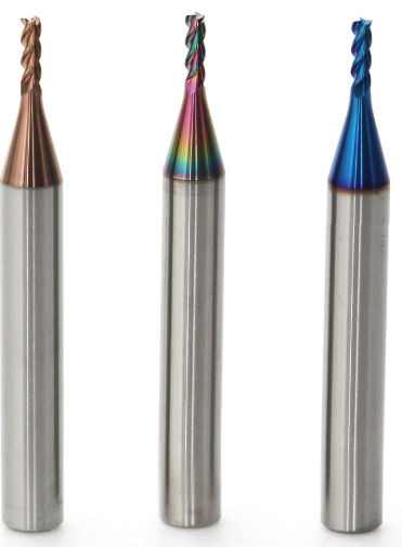
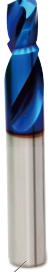
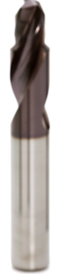
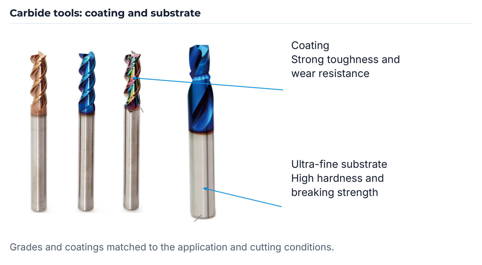
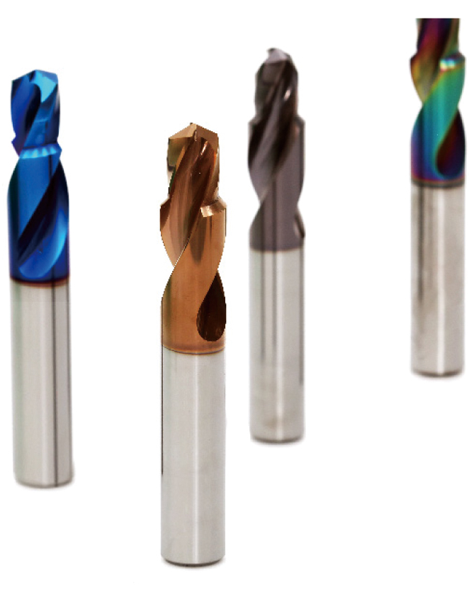
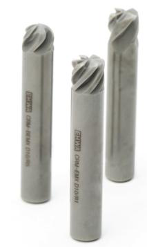
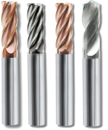
EHWA matches carbide grades and coatings to the application and machining conditions. The coating supports strong toughness and wear resistance; the ultra-fine substrate combines high hardness with high breaking strength. The tool images preserve the different coated end-mill and drill designs and the small tool variants.


Rotating tools for aluminium, CFRP and HRSA
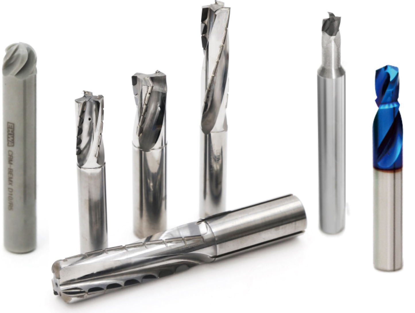
Aluminium and CFRP support lightweight aerospace designs with a favourable strength-to-weight ratio. Abrasive fibres and the directional structure of CFRP place particular demands on cutting edges and wear resistance. EHWA offers rotating tools with sharp cutting edges and high wear resistance for these applications. Helical end mills target high feed, high material removal and reliable processes. For nickel alloys such as Inconel in turbine and jet-engine components, a helical ceramic end mill complements the HRSA range.

Product lines: TC, ceramic and PCD
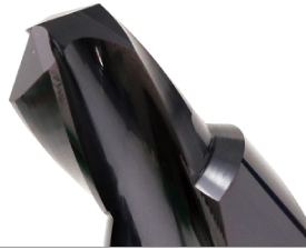
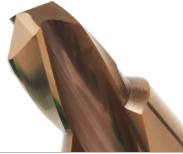
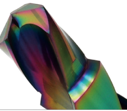
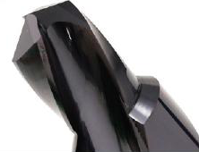
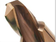
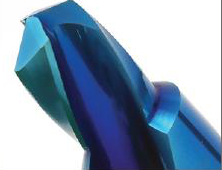
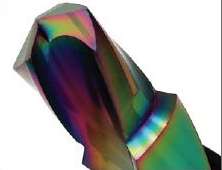
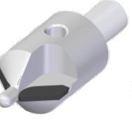
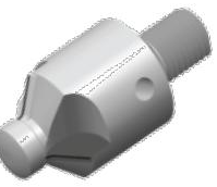
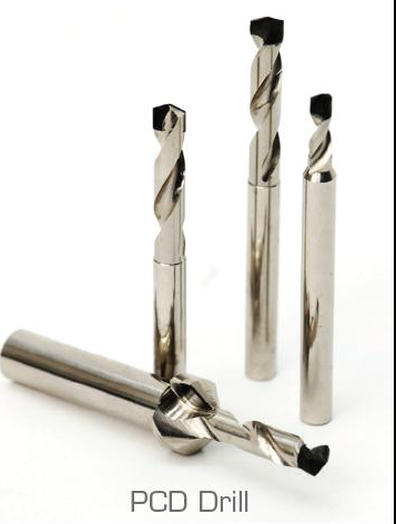
The product overview distinguishes TC versions TA, H1, H2 and H3, ceramic designs 6F, BALL and 4F, and PCD versions 1Z, 2Z and 3Z. TC end mills and PCD drills are also shown as complete tool groups. The illustrations preserve the individual head designs and coating colours.
| Tool group | Design |
|---|---|
| TC | TA |
| TC | H1 |
| TC | H2 |
| TC | H3 |
| Ceramic | 6F |
| Ceramic | BALL |
| Ceramic | 4F |
| PCD | 1Z |
| PCD | 2Z |
| PCD | 3Z |



Helical PCD end mills
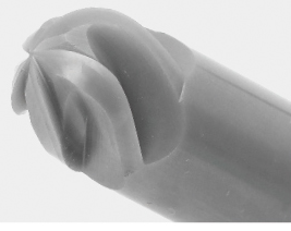
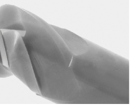
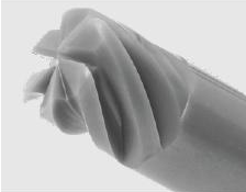
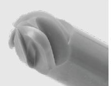
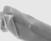
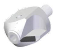
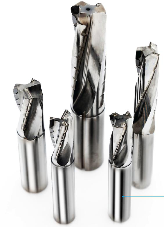
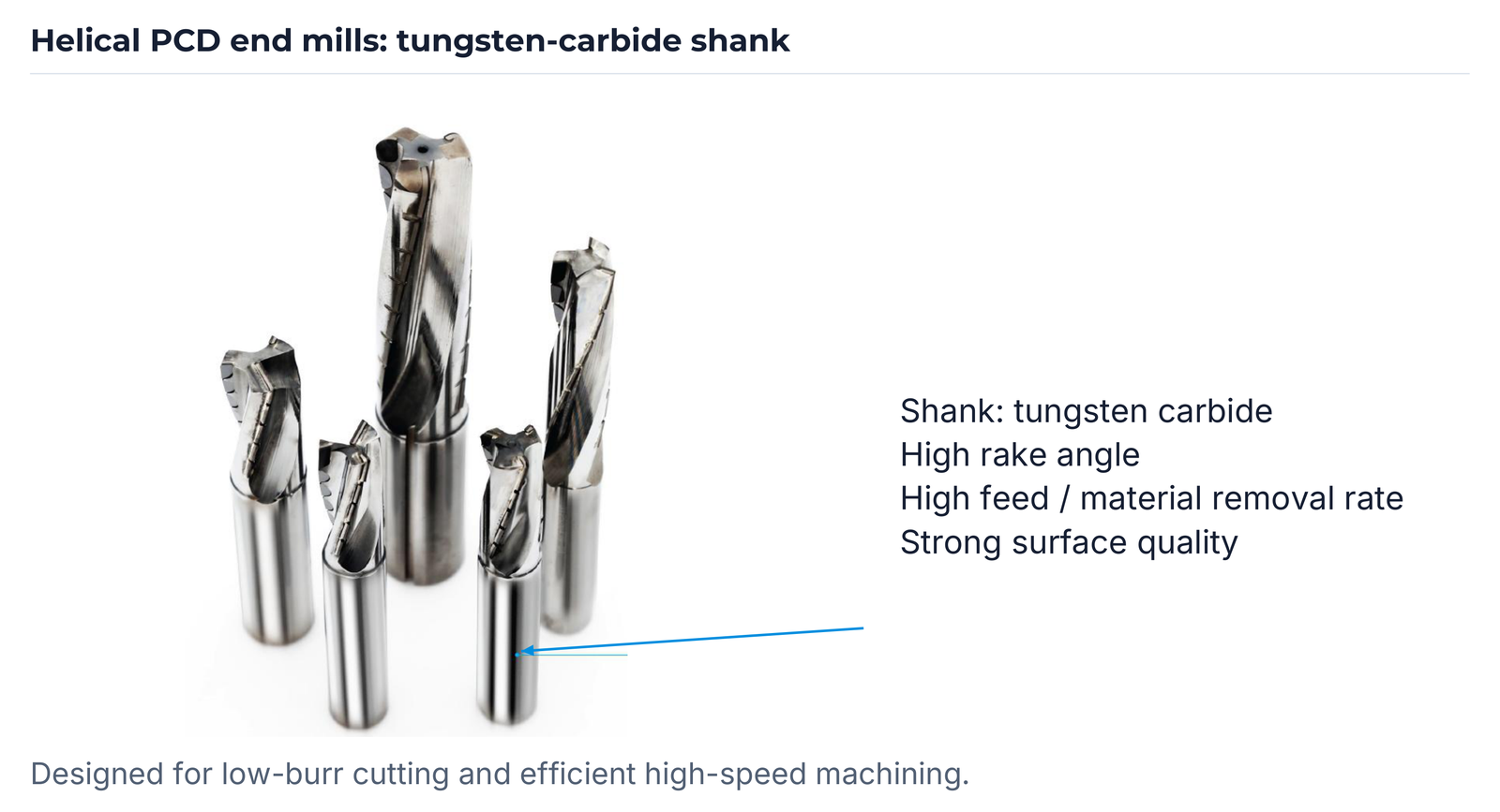
Helical PCD end mills combine high feed and material removal with geometry designed for reliable machining. A high rake angle supports low-burr cutting; further features are high speed, high efficiency and good surface finish. The shank is tungsten carbide. Tool and process are matched to the component and material.
EC2008: ceramic end mills for HRSA
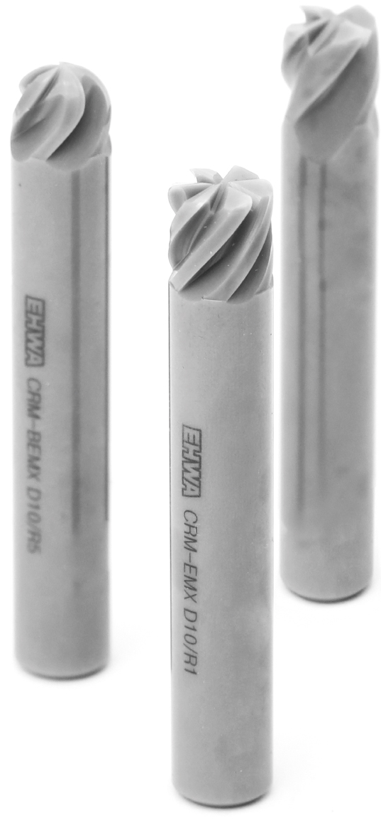
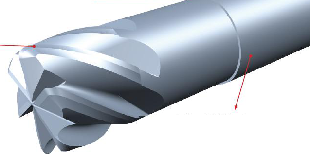
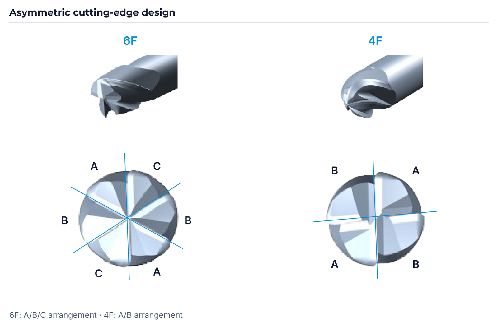
SiAlON ceramic is based on silicon (Si), aluminium (Al), oxygen (O) and nitrogen (N). The EC2008 material description emphasises high heat resistance and low thermal conductivity. These thermal properties support tool design for demanding machining conditions involving high temperatures and pressure loads, such as turbine and automotive-engine components. The large helix angle is intended to reduce cutting load and enable strong cutting performance. The asymmetric cutting-edge design is shown as A/B/C for 6F and A/B for 4F. The source states no additional angle or thermal-conductivity values.
| Feature | EHWA statement |
|---|---|
| Grade | EC2008 |
| Material | SiAlON |
| Colour | Dark Olive Green |
| Workpiece | HRSA (Heat-Resistant Super Alloy) |


ET220: solid carbide drills for steel
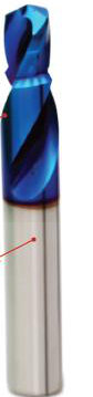
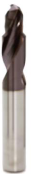
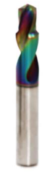
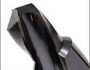
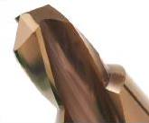
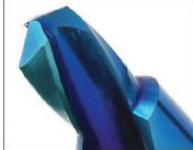
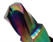
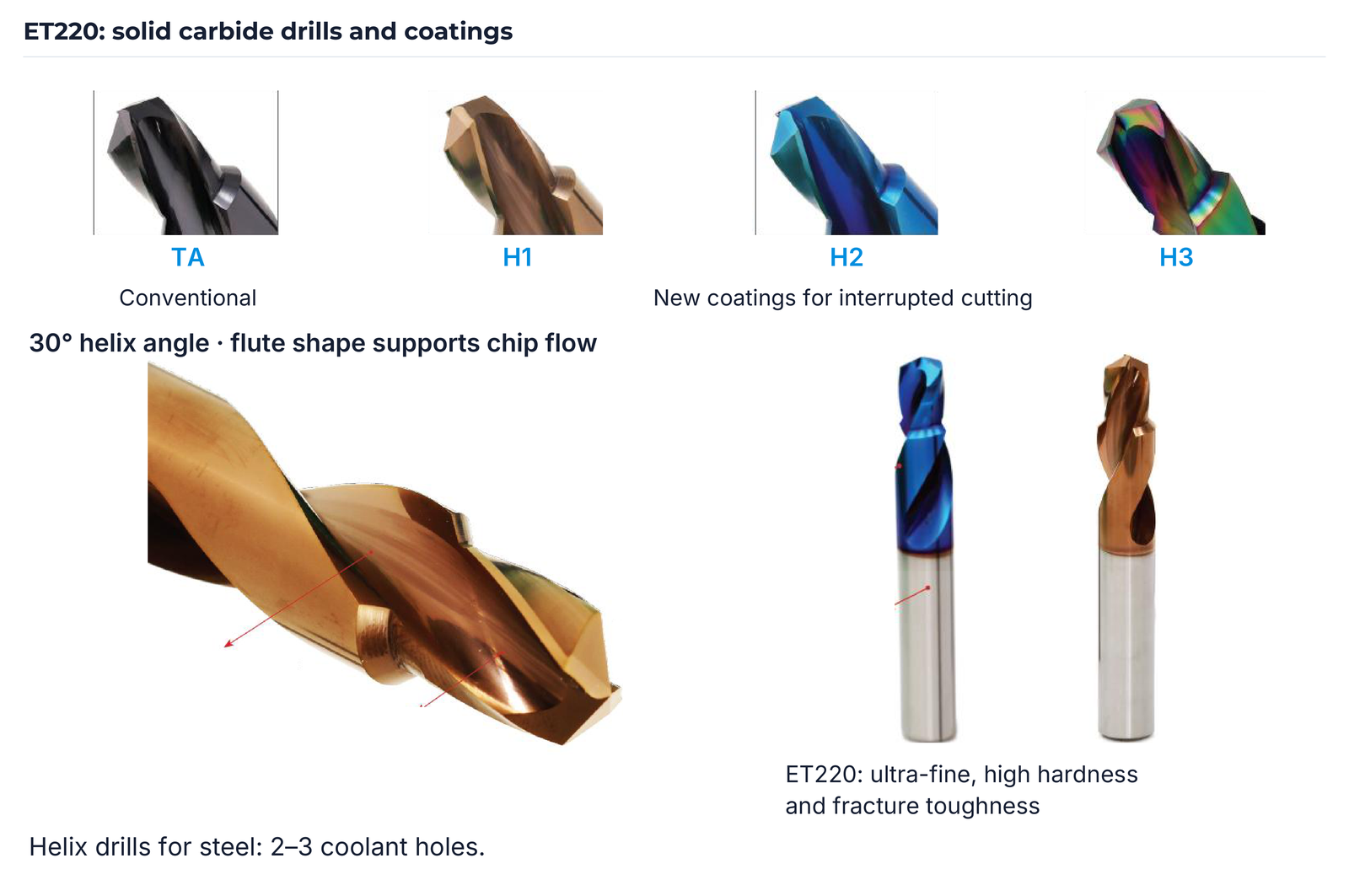
ET220 is described as ultra-fine carbide with high hardness and high fracture toughness. The helix drills for steel have 2–3 coolant holes. A 30° helix angle and a flute shape designed for smooth chip evacuation complement the coating with strong toughness and wear resistance. The coating overview separates the conventional TA design from H1, H2 and H3 for interrupted cutting.
| Feature | EHWA statement |
|---|---|
| Grade | ET220 |
| Substrate | Ultra-fine; high hardness and fracture toughness |
| Workpiece | Steel |
| Coolant holes | 2–3 |
| Helix angle | 30° |
| Flute shape | Supports chip flow |
| Coating | Strong toughness / wear resistance |
| Series | Classification |
|---|---|
| TA | Conventional coating |
| H1 | New coating for interrupted cutting |
| H2 | New coating for interrupted cutting |
| H3 | New coating for interrupted cutting |


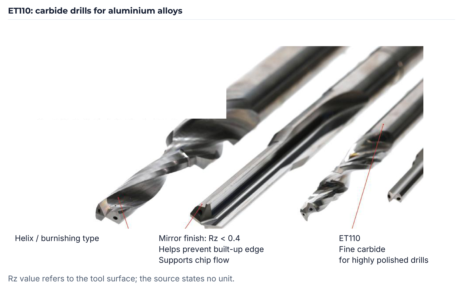
ET110: drills for aluminium alloys
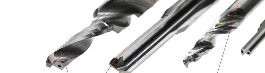
ET110 uses fine carbide with a polished surface and is described for highly polished drills. The range shows helix and burnishing drill designs. The tool-surface statement Rz < 0.4 is associated with reducing built-up edge and supporting chip flow. No unit is stated for this Rz value in the source; it is not a roughness value of a machined hole.
| Feature | EHWA statement |
|---|---|
| Grade | ET110 |
| Workpiece | Aluminium alloys |
| Substrate | Fine carbide |
| Surface | Polished; Rz < 0.4 |
| Designs | Helix drills / burnishing drills |

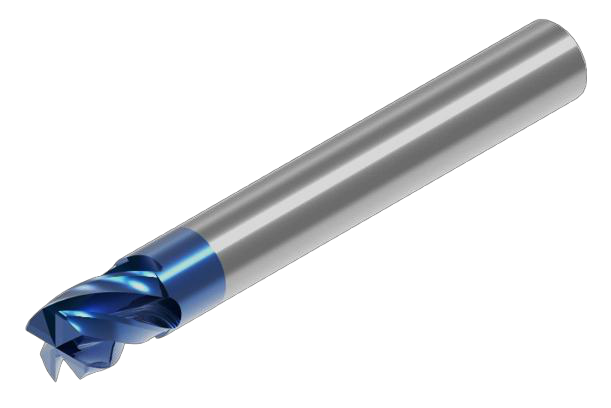
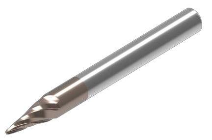
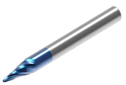
Solid carbide end mills: three designs
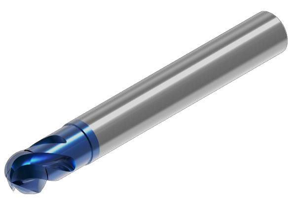
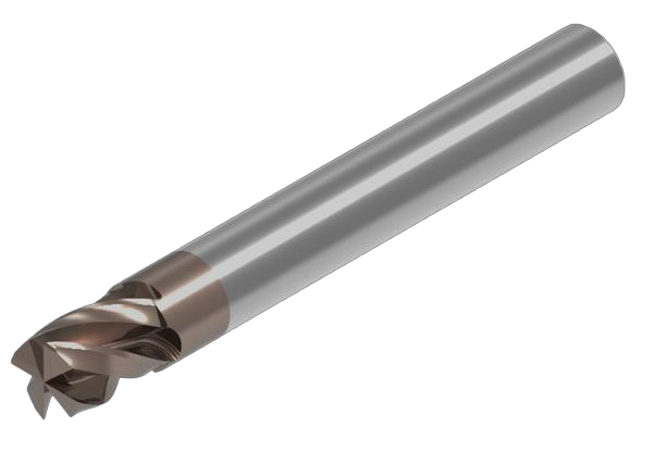
Ball end mills, square end mills for side and planar machining, and taper ball end mills complement the range. The application table preserves the different machining tasks. Each design is illustrated with both coating variants shown in the source.
| Design | Application |
|---|---|
| Ball end mill | Curved surfaces; roughing; finishing |
| Square end mill | Side and planar machining; roughing; finishing |
| Taper ball end mill | Curved surfaces; finishing |

Match tool and process together
For selection, provide the material, drawing or component profile, machine model and mounting, machining task and required surface. EHWA Europe matches design, bond, grade and variant to these details.
EHWA Europe · info@ehwadia.de · +49 6173 997780