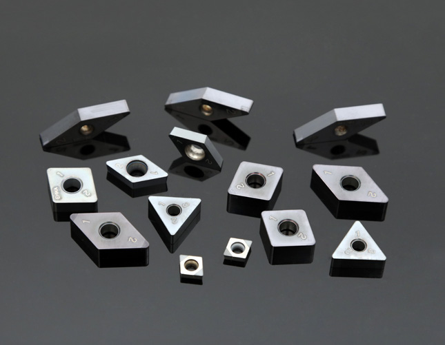
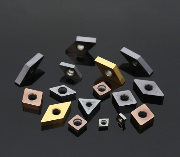
This collection brings together product data from twelve EHWA documents. It covers D-BITE, PCD and PCBN milling tools, carbide drills, coatings, optical tools and inserts for selection by machining task.
This catalogue combines the complete technical content of twelve short EHWA product documents. D-BITE precision tools, PCD, PCBN, carbide and coatings remain distinct tool or material concepts. Series and article designations and technical differences between individual applications are retained.
The tables reproduce the programmes in their respective sources. Historical lists labelled “Stock” serve as product and specification references here; current stock and a suitable design are discussed with EHWA Europe. Test results remain directly associated with their cutting conditions.
Editorial edition: 13 October 2026. This date identifies the new editorial version rather than redating every underlying HQ document.
Industry images from the solid carbide drill product sheet
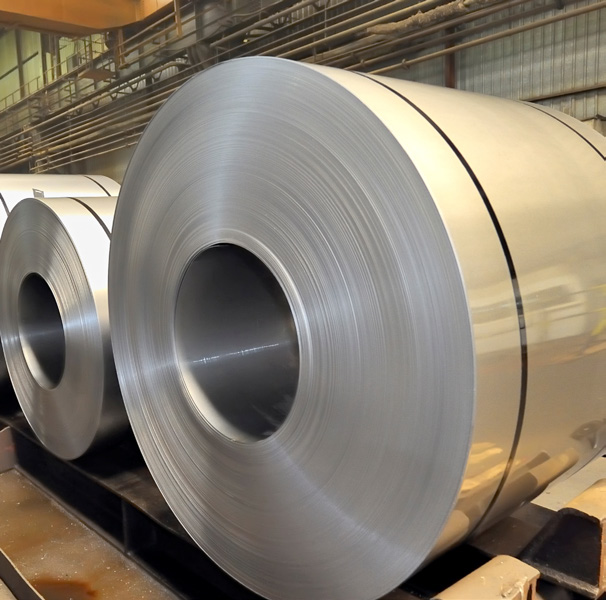
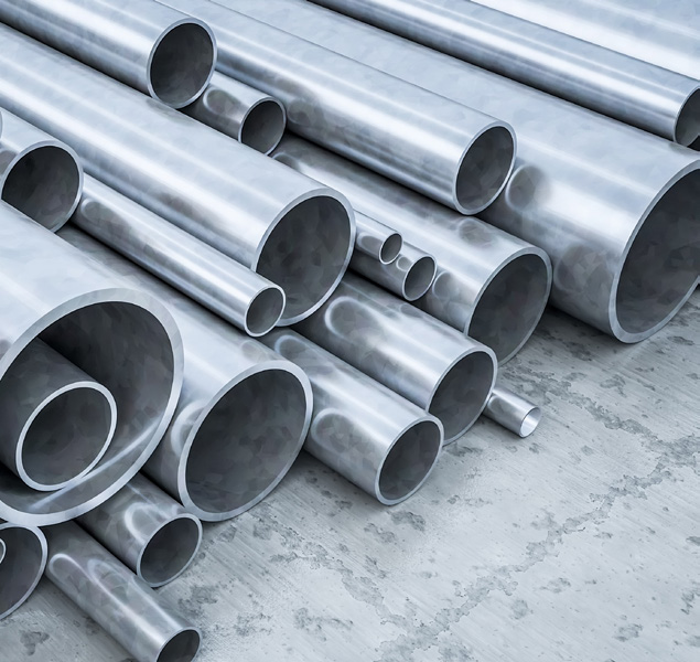
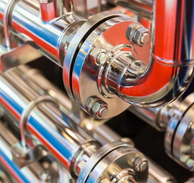
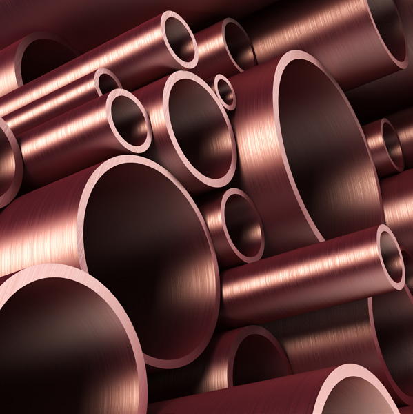
The solid carbide drill cover shows vehicle manufacturing and strip and tubular products as industry images. These photographs provide industrial context. Suitability for a particular material is defined by the respective tool programme; the images do not extend the steel application described for ET220.
Vehicle manufacturing as an industry image.Metal strip as an industry image.Tubular products as an industry image; material not specified in the photograph.Industrial piping as an industry image.Copper-coloured tubular products as an industry image.
D-BITE and PCD milling tools for precision applications
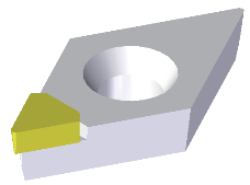
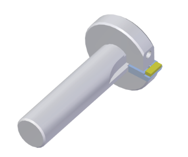
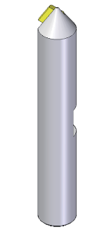
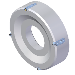
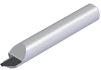
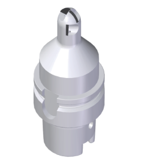
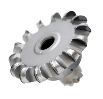
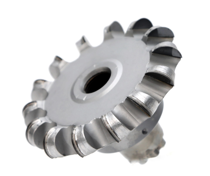
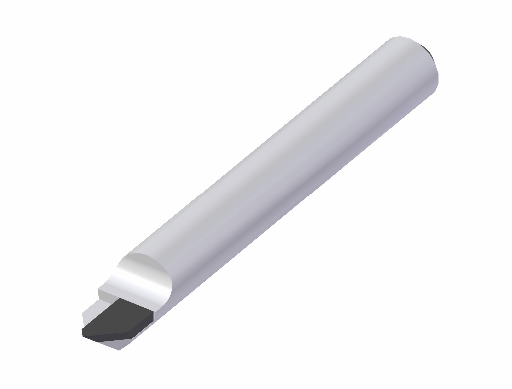
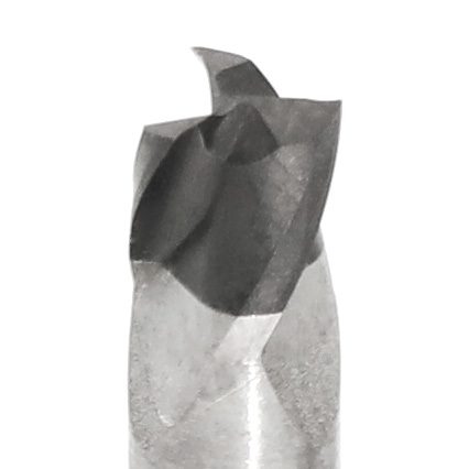
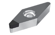
The D-BITE document lists smartphones, metal moulds and patterning, optical lenses and BLU/PF applications. BLU and PF remain source designations. Illustrated tool types include inserts, chamfering tools and two designs labelled Locking Type.
D-BITE product group from the EHWA document.D-BITE insert design.D-BITE chamfering tool.First D-BITE design labelled Locking Type.Second D-BITE design labelled Locking Type.
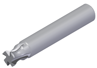
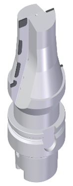
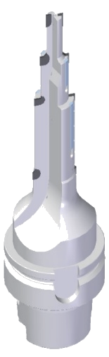
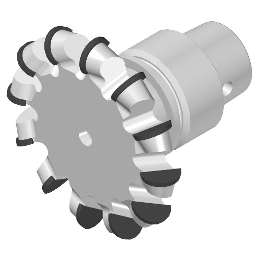
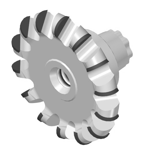
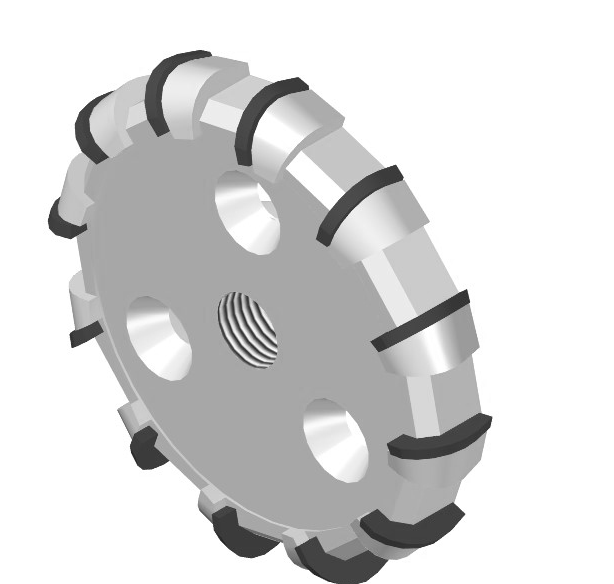
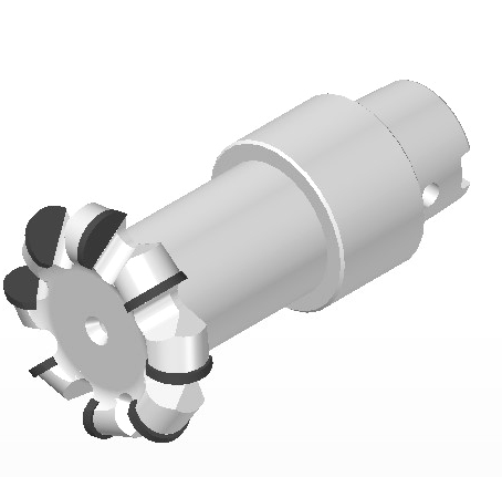
The separately described PCD-Endmill group lists smartphones, automotive manufacturing, aircraft, wind power, MMC, CFRP and FRP as applications. The image sequence shows seven different milling and tool forms; the document does not provide individual article codes or dimensions.
PCD-Endmill: first illustrated tool form.PCD-Endmill: second illustrated tool form.PCD-Endmill: third illustrated tool form.PCD-Endmill: fourth illustrated tool form.PCD-Endmill: fifth illustrated tool form.PCD-Endmill: sixth illustrated tool form.PCD-Endmill: seventh illustrated tool form.
D-BITE and PCD-Endmill are separate tool groups. Selection identifies the actual tool form, cutting material and required edge quality. The source bears a January 2017 printing statement; its applications and forms remain a traceable programme reference.
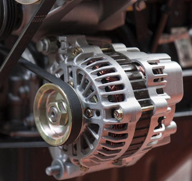
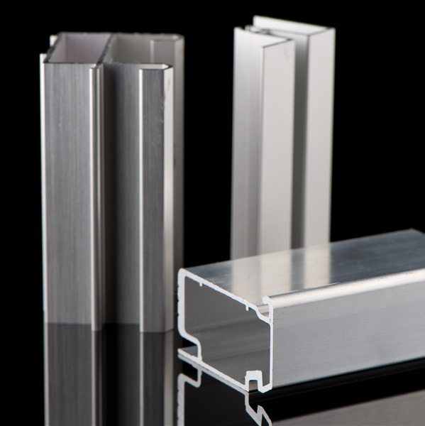
The aluminium document illustrates automotive applications, stock materials, alternator/motor components, drum components and profiles. The programme includes helical drills (Helix Type) and Burnishing Type drills.
Automotive application image for aluminium drills.Aluminium stock materials as an application image.Alternator/motor component as an application image.Drum component as an application image.Aluminium profiles as an application image.Carbide drills for aluminium alloys: tool group.
ET110 is described as a fine carbide material with a polished surface for highly polished drills. The polished tool surface is intended to prevent built-up edge formation and support smooth chip flow. The source identifies “Mirror Finish Lower than Rz 0.4”. Rz < 0.4 remains associated with the illustrated tool surface; no unit is printed there. It is not presented as a guaranteed roughness of the resulting hole.
Helical and burnishing designs with polished tool surfaces.Polished flute surface of the ET110 drill.
EHWA drill code and dimensional labels
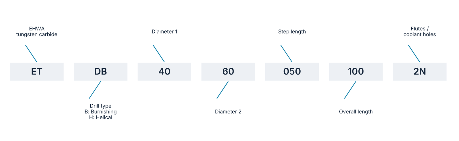
The code example is ET DB 40 60 050 100 2N.
Code element
Meaning given by EHWA
ET
EHWA; T denotes tungsten carbide
DB
Drill type; B = Burnishing Drill, H = Helical
40
Diameter 1
60
Diameter 2
050
Step length
100
Overall length
2N
Flute-number/oil-hole designation
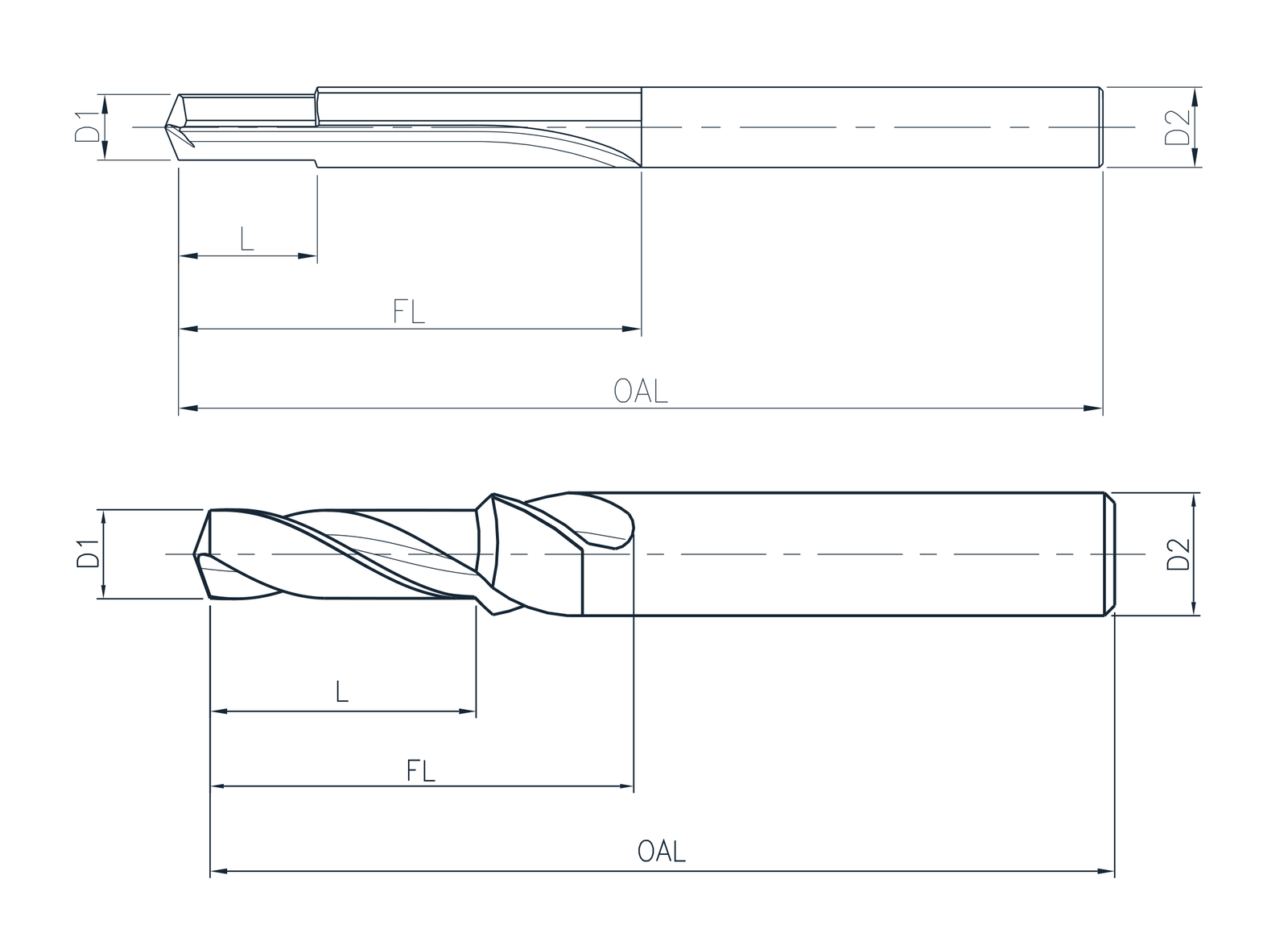
EHWA drill code with the seven elements identified.Drill dimension diagrams showing D1, D2, L, FL and OAL.
The drawings identify D1 and D2 as diameters and L, FL and OAL as length labels. OAL is overall length. The following table reproduces all six illustrated designs and the source dimensional designations.
Item code
D1
D2
L
FL
OAL
ETDB 43 60 025 080 2N
4.3
6.0
25
40
80
ETDB 51 80 025 080 2N
5.1
8.0
25
40
80
ETDB 69 100 030 100 2N
6.9
10.0
30
50
100
ETDB 86 120 035 105 2N
8.6
12.0
35
55
105
ETDB 104 140 040 110 2N
10.4
14.0
40
60
110
ETDB 140 160 040 110 2N
14.0
16.0
40
60
110
The complete code belongs with its corresponding dimensions. Mounting, hole depth, chip evacuation and required hole quality determine the appropriate design. The source printing statement is June 2024.
Standard coatings: properties and application ranges
The coating document distinguishes eight grade designations. The following table contains every colour, hardness value, temperature value and feature. HV and °C are established by the supplementary EHWA Coating Service table; all numbers remain the values in the coating document reproduced here.
Grade
Colour
Hardness (HV)
Maximum temperature (°C)
Features described by EHWA
TN
Gold
2300
600
Single-layer coating; typically used for wear parts; used insert edges easy to identify
TA
Purple grey
2300
900
Good heat and wear resistance; conventionally used for cutting tools
AC
Silver grey
3200
1100
Better heat resistance than TA; high hot hardness and oxidation resistance
AC2
Light grey
3700
1100
High heat resistance; higher hot hardness and oxidation resistance than AC
TNP
Dark grey
3600
1100
High wear resistance, good surface finish and heat resistance; described for hardened steel and bearing steel
H1
Copper
3600
1200
Multilayer coating for interrupted cutting; high wear and oxidation resistance
H2
Blue
4000
1200
Multilayer coating for interrupted cutting; high wear and oxidation resistance
H3
Rainbow
3600
1200
Multilayer coating for interrupted cutting; high wear and oxidation resistance
The 1200 value is shared by H1/H2/H3 in the original table. “New” markers for AC2 and H1/H2/H3 describe the source's historical edition; they are not presented as current launches.
EHWA designation
Coating name in the application matrix
TN
TiN
TA
TiAlN
AC
AlCrN
AC2
AlCrN +
TNP
AlTiN +
H1
TiSiN +
H2
TiSiN +
H3
TiSiN +
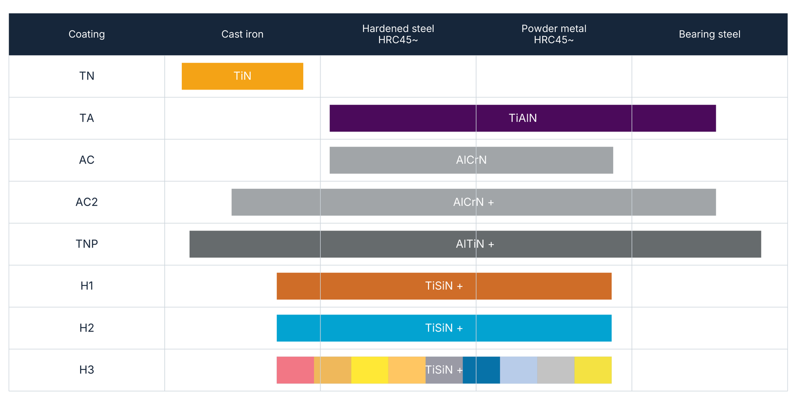
Coating application matrix for cast iron, hardened steel, powder metal and bearing steel; original range bars retained.
The matrix distinguishes cast iron, hardened steel labelled HRC45~, powder metal labelled HRC45~, and bearing steel. Its bars show different application ranges within and across these columns. The plus signs remain part of the printed coating names; no additional chemical formula is inferred from them. Coating, cutting material and continuous or interrupted cutting are selected together. The source printing statement is June 2024.
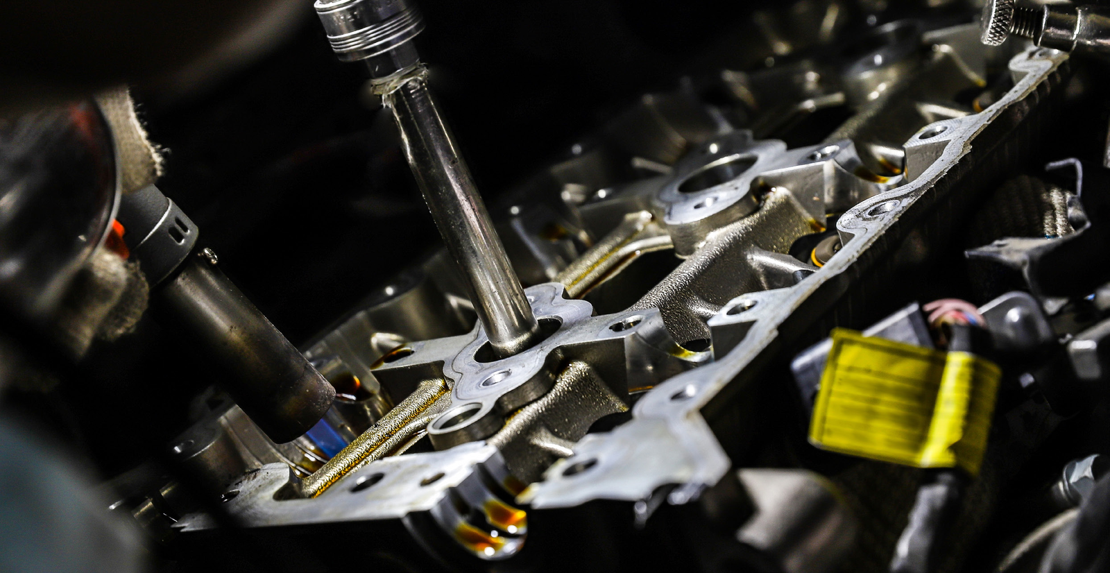
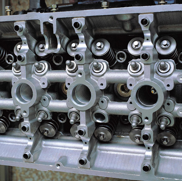
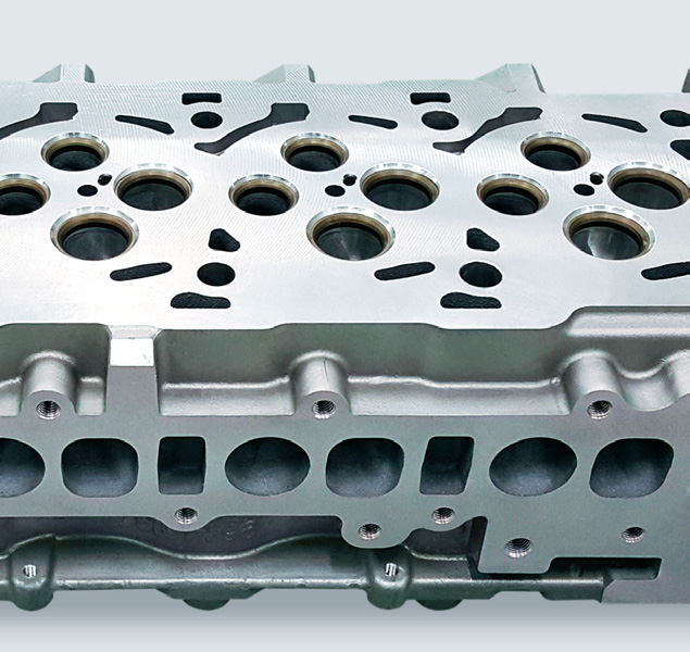
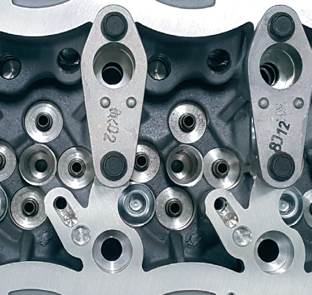
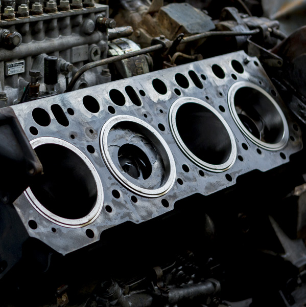
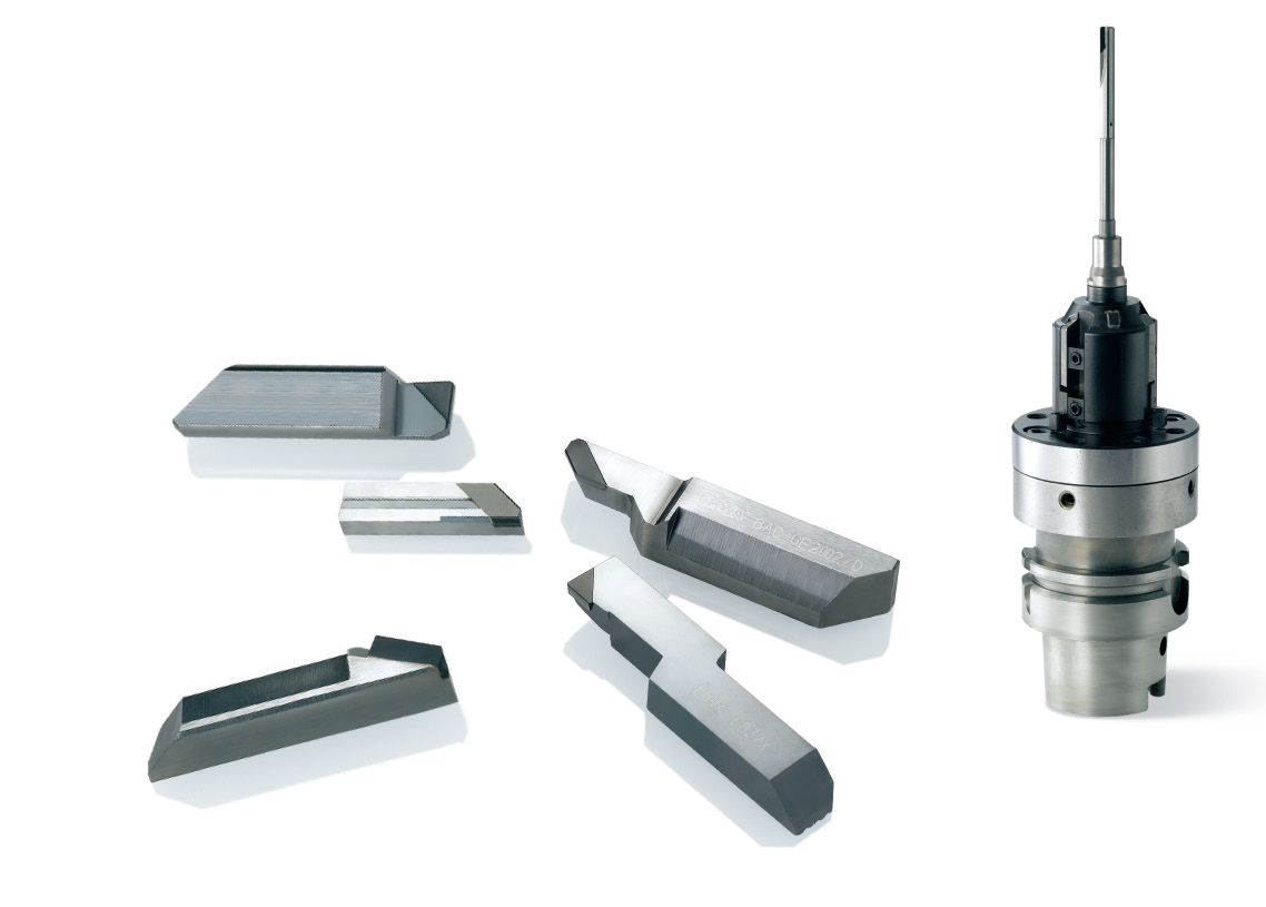
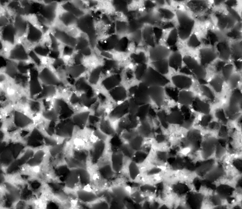
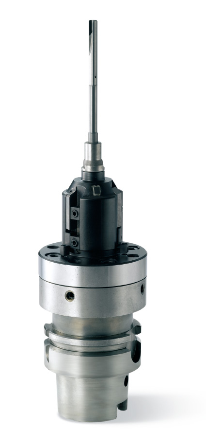
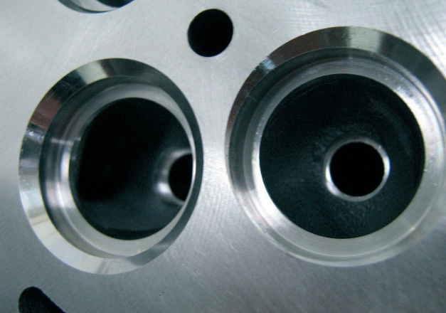
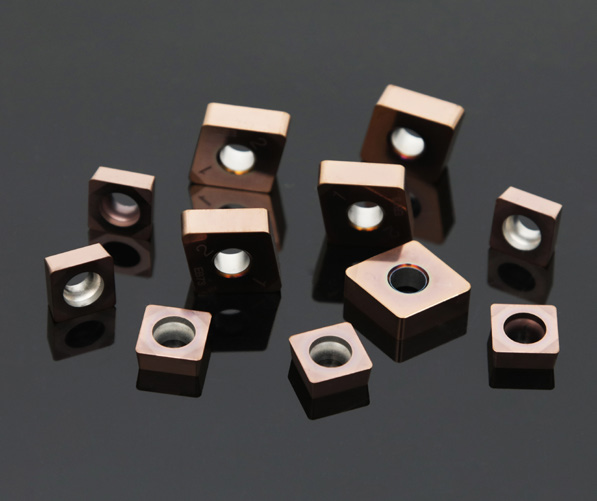
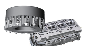
EB150 is developed for valve seat rings in engine cylinder heads. A TiN-based ceramic binder and CBN grains support impact and wear resistance, useful tool life and good surface finish. The grade is designed for hardness variations in sintered alloys; EHWA also identifies applications in high-output engines.
Valve seat machining on a cylinder head.First cylinder-head application image.Second cylinder-head application image.Third cylinder-head application image.Fourth engine-component application image.EB150 inserts and valve seat tool as a product group.
Grade
Grit size
CBN volume content
Listed application characteristics
EB150
2–3 µm
60%
High-alloyed P/M; hardened steel HRC > 45; valve seat ring B 45°; H15–H25
P/M and H15–H25 remain source designations. The 45° designation remains associated with the valve seat ring.
Microstructure image of EB150.EB150 cutting inserts.Tool for valve seat machining.Valve seat as a workpiece example.
Complete cutting example
Parameter
Information in the results block
Operation
Exhaust valve seat
Cutting material
PCBN EB150
Spindle speed
1500 min⁻¹
Feed rate
0.05 mm/tooth
Coolant
wet
Result
2400 holes
The original line says “Cutting speed: 1500 rpm”; the unit correctly identifies spindle speed rather than cutting speed in m/min.
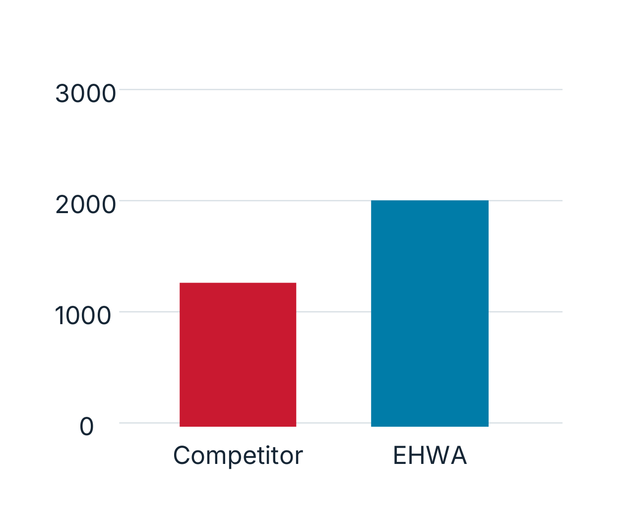
Separate EB150 comparison chart with competitor and EHWA bars; original scale 0–3000 retained.
The adjacent chart is a separate comparison without a printed axis unit. Its bar geometry is not harmonised with the result of 2400 holes. All conditions and the value explicitly reported in the results block are retained. The source printing statement is June 2024.
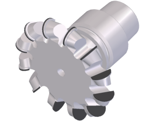
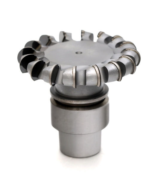
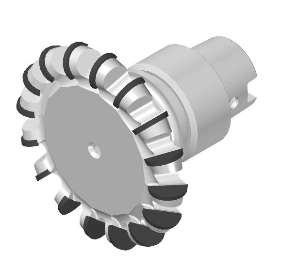
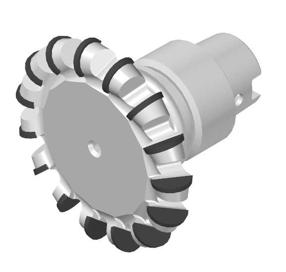
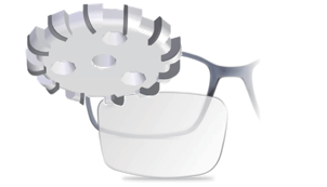
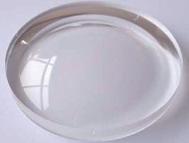
EHWA identifies polycarbonate, CR-39 and high-index lens materials (Hi Index) for spectacle lens generating. Tool design combines long useful life with good surface finish. The document illustrates optical applications and six specific cutter designs.
Optical lenses as the main application image.First spectacle lens application image.Second spectacle lens application image.Third spectacle lens application image.Fourth spectacle lens application image.First optical tool from the product group.Second optical tool from the product group.
Specification
Cutting edges
Listed feature
66D-16Z-HSK32E(C)
16Z
Higher feed; CW/CCW
66D-15Z-HSK32E(C)
15Z
Higher feed; CW/CCW
66D-12Z-HSK32E(C)
12Z
CW/CCW
66D-14Z-flw
14Z
14 cutting edges
67.5D-12Z-disc
12Z
CW/CCW
45D-8Z-HSK32C
8Z
CW/CCW
CW and CCW identify the directions of rotation given in the source. The 14Z design does not have a corresponding direction statement there; features of the other designs are not automatically transferred to it. The 16Z design is highlighted as a new product form in the historical sheet.
Optical cutter with visible tool designation.Disk-type optical cutter as a product detail.Design 66D-16Z-HSK32E(C).Design 66D-15Z-HSK32E(C).Design 66D-12Z-HSK32E(C).Design 66D-14Z-flw.Design 67.5D-12Z-disc.Design 45D-8Z-HSK32C.
Codes remain unchanged, including the decimal point in 67.5D and the mounting designations. Material, required lens surface, machine, rotation and mounting are matched together. The source printing statement is June 2024.
EHWA describes PCBN endmills for precise, efficient cutting of flexible dies. Performance and durability are associated with different PCBN grade selections and precise CNC machining. The objectives are accurate contours and good surface roughness. Tooling is designed to customer requirements.
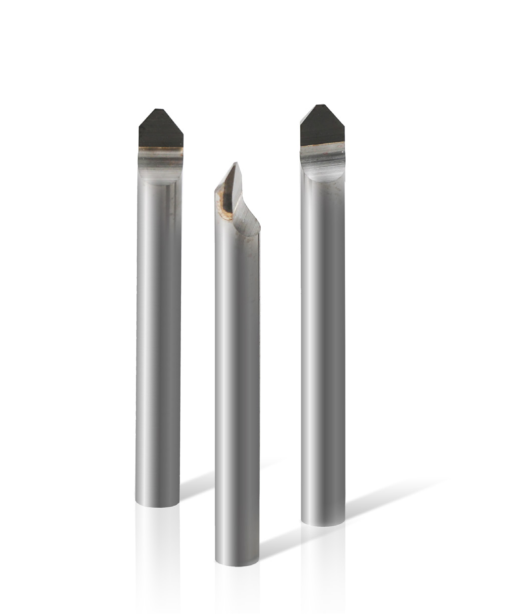
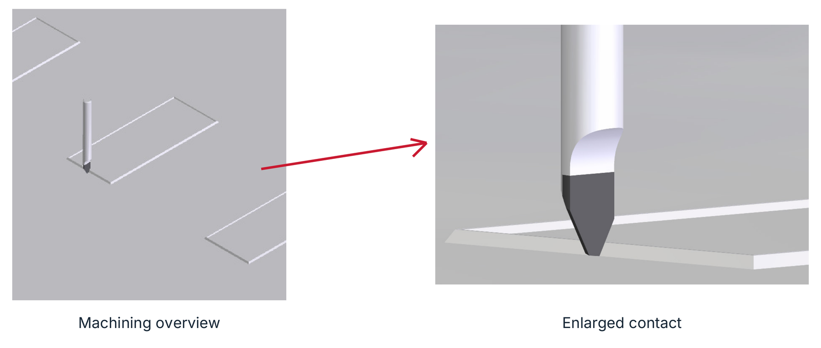
Flexible dies as the main application image.First flexible-die application detail.Second flexible-die application detail.Third flexible-die application detail.Fourth flexible-die application detail.PCBN endmills as a tool group.Further flexible-die application image.PCBN endmills as a product detail.Flexible-die cutting diagram with an enlarged cutting-edge contact.
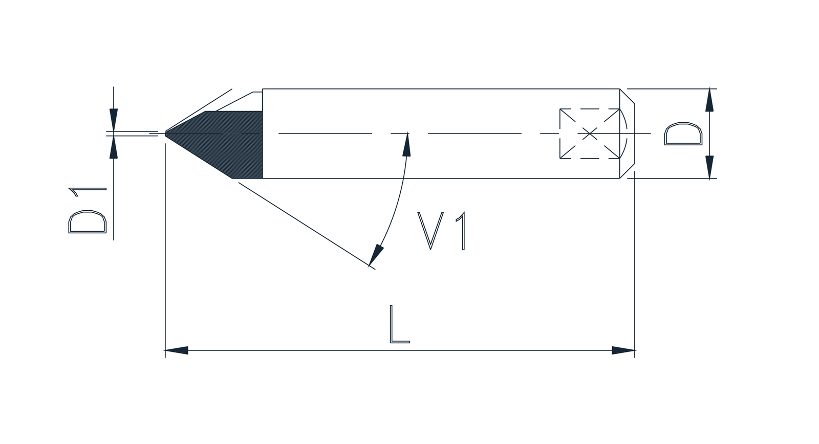
The specification includes all ten combinations below. D and L are explicitly given in mm. The third table column is labelled V; the dimension diagram labels the angular region V1. These two source designations remain separately identifiable.
D (mm)
L (mm)
V, source value
3
26
35
3
30.2
20
3
30.2
30
3
30.2
40
4
30
25
4
30
30
6
30
20
6
30
25
6
30
35
6
30
80
PCBN endmill dimension diagram showing D, D1, L and V1.Illustrated cutting-edge design of the PCBN endmill.
The table provides no D1 value or explicitly printed unit for V. Required angular and tip dimensions are matched to the actual contour and drawing. Every listed V value is retained. The source printing statement is June 2024.
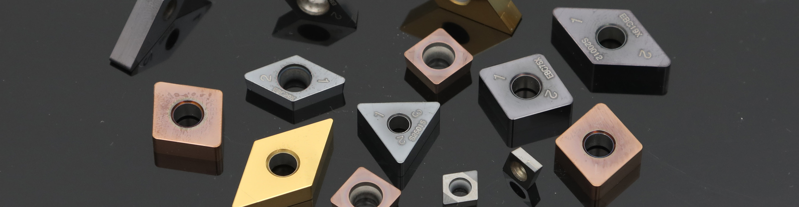
The two-page PCBN list distinguishes EB428 GS, EB419 GS, EB454 GS, EB71X LT and EB210 MT. All 21 model groups and 63 variant rows are reproduced below. Model forms and coated product groups remain visible.
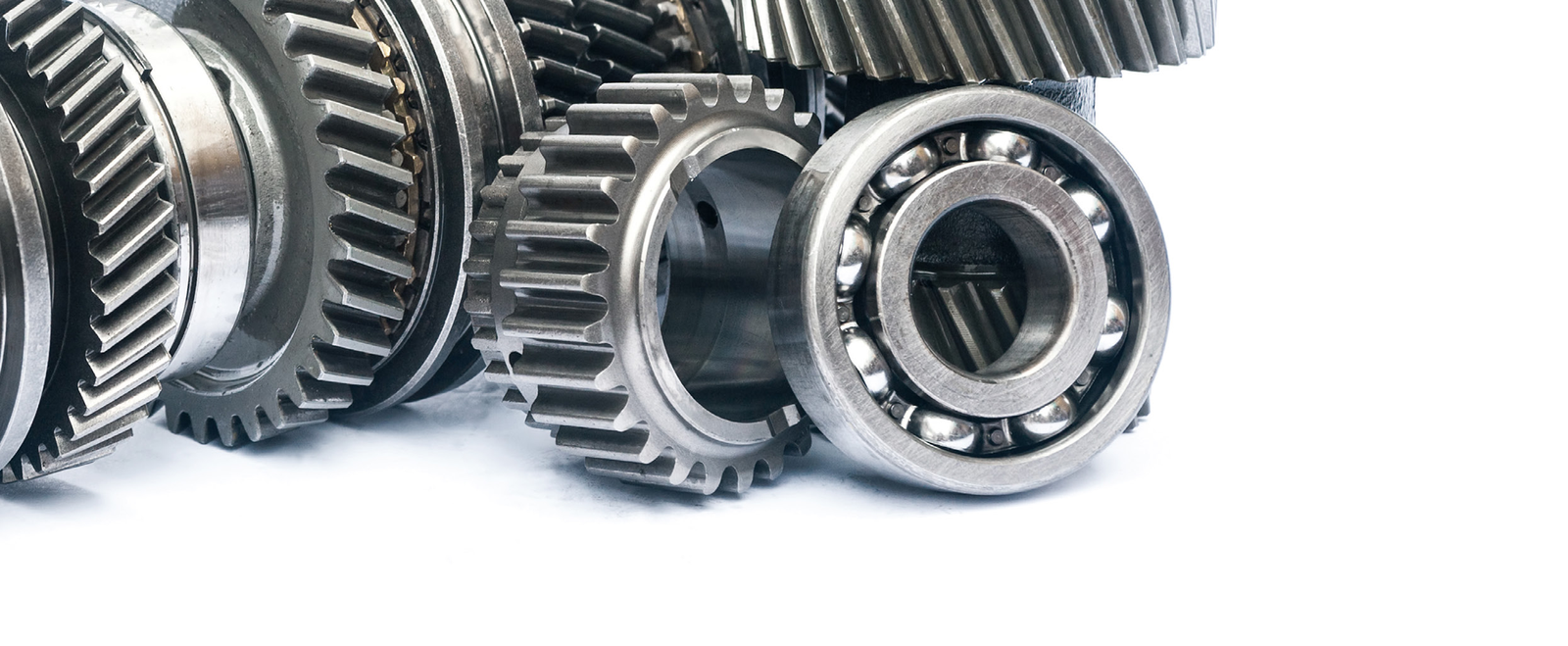
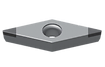
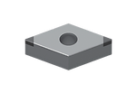
PCBN inserts: product overview.First PCBN product group.Second PCBN product group.Third PCBN product group.Fourth PCBN product group.Gears and bearings as the PCBN list's application image.
Metric and inch row designations are reproduced as printed: a complete model designation is sometimes followed only by radius suffixes 04, 08 or 12 and 1, 2 or 3. TIP is the source's tip-count designation; Nose R is the original radius column. ● remains the historical list's marker. A ● without an article code is retained, as is a printed code without ●; no presumed number is added. — denotes an empty original cell rather than zero.
TPGW090202 · TIP 3
PCBN TPGW090202: illustrated model form.
Metric designation
Inch designation
Nose R
EB428 GS
EB419 GS
EB454 GS
EB71X LT
EB210 MT
TPGW090202
TPGW2(1.5)0.5
0.2
—
—
—
—
—
04
1
0.4
● EB03T330506004
—
—
—
—
08
2
0.8
—
—
—
—
—
TPGW110202 · TIP 3
PCBN TPGW110202: illustrated model form.
Metric designation
Inch designation
Nose R
EB428 GS
EB419 GS
EB454 GS
EB71X LT
EB210 MT
TPGW110202
TPGW3(1.5)0.5
0.2
—
—
—
—
—
04
1
0.4
● EB03T360506004
—
—
—
—
08
2
0.8
EB03T360506004
—
—
—
—
TPGW110302 · TIP 2
PCBN TPGW110302: illustrated model form.
Metric designation
Inch designation
Nose R
EB428 GS
EB419 GS
EB454 GS
EB71X LT
EB210 MT
TPGW110302
VNGA430.5
0.2
—
—
—
—
—
04
1
0.4
● EB03T360506004
● EB03T392406004
● EB03T391806004
—
● EB03T393003000
08
2
0.8
●
—
—
● EB03T403301000
—
VNGA160402 · TIP 2
PCBN VNGA160402: illustrated model form.
Metric designation
Inch designation
Nose R
EB428 GS
EB419 GS
EB454 GS
EB71X LT
EB210 MT
VNGA160402
VNGA430.5
0.2
—
—
—
—
—
08
1
0.4
● EB02V020506004
● EB02V022406004
● EB02V021806004
● EB02V023301000
—
12
2
0.8
● EB02V030506004
● EB02V032406004
● EB02V031806004
● EB02V033301000
—
VBGW110302 · TIP 2
PCBN VBGW110302: illustrated model form.
Metric designation
Inch designation
Nose R
EB428 GS
EB419 GS
EB454 GS
EB71X LT
EB210 MT
VBGW110302
VBGW320.5
0.2
● EB02V050506004
—
● EB02V051806004
—
—
04
1
0.4
● EB02V060506004
—
● EB02V061806004
—
—
08
2
0.8
—
—
—
—
—
VBGW160402 · TIP 2
PCBN VBGW160402: illustrated model form.
Metric designation
Inch designation
Nose R
EB428 GS
EB419 GS
EB454 GS
EB71X LT
EB210 MT
VBGW160402
VBGW430.5
0.2
● EB02V080506004
● EB02V082406004
● EB02V081806004
● EB02V083301000
● EB02V083003000
04
1
0.4
● EB02V090506004
● EB02V092406004
● EB02V091806004
● EB02V093301000
● EB02V093003000
08
2
0.8
● EB02V100506004
● EB02V102406004
● EB02V101806004
● EB02V103301000
● EB02V103003000
VCGW110302 · TIP 2
PCBN VCGW110302: illustrated model form.
Metric designation
Inch designation
Nose R
EB428 GS
EB419 GS
EB454 GS
EB71X LT
EB210 MT
VCGW110302
VCGW320.5
0.2
—
—
—
—
—
04
1
0.4
● EB02V150506004
—
● EB02V151806004
—
—
08
2
0.8
—
—
—
—
—
VCGW160402 · TIP 2
PCBN VCGW160402: illustrated model form.
Metric designation
Inch designation
Nose R
EB428 GS
EB419 GS
EB454 GS
EB71X LT
EB210 MT
VCGW160402
VCGW430.5
0.2
● EB02V170506004
● EB02V172406004
● EB02V171806004
—
—
04
1
0.4
● EB02V180506004
● EB02V182406004
● EB02V181806004
—
—
08
2
0.8
● EB02V190506004
● EB02V192406004
—
—
—
WNGA080404 · TIP 3
PCBN WNGA080404: illustrated model form.
Metric designation
Inch designation
Nose R
EB428 GS
EB419 GS
EB454 GS
EB71X LT
EB210 MT
WNGA080404
WNGA431
0.4
—
—
—
—
—
08
2
0.8
● EB03W070506004
● EB03W072406004
● EB03W071806004
—
● EB03W073003000
CNGA120402 · TIP 2
PCBN CNGA120402: illustrated model form.
Metric designation
Inch designation
Nose R
EB428 GS
EB419 GS
EB454 GS
EB71X LT
EB210 MT
CNGA120402
CNGA430.5
0.2
—
—
—
—
—
04
1
0.4
● EB02C020506004
● EB02C022406004
● EB02C021806004
—
● EB02C023003000
08
2
0.8
● EB02C030506004
● EB02C032406004
● EB02C031806004
● EB02C033301000
—
12
3
1.2
● EB02C040506004
● EB02C042406004
● EB02C041806004
● EB02C043301000
—
CCGW060202 · TIP 2
PCBN CCGW060202: illustrated model form.
Metric designation
Inch designation
Nose R
EB428 GS
EB419 GS
EB454 GS
EB71X LT
EB210 MT
CCGW060202
CCGW2(1.5)0.5
0.2
● EB02C120506004
● EB02C122406004
● EB02C121806004
—
—
04
1
0.4
● EB02C130506004
● EB02C132406004
● EB02C131806004
● EB02C133301000
—
08
2
0.8
—
● EB02C142406004
—
—
—
CCGW09T302 · TIP 2
PCBN CCGW09T302: illustrated model form.
Metric designation
Inch designation
Nose R
EB428 GS
EB419 GS
EB454 GS
EB71X LT
EB210 MT
CCGW09T302
CCGW3(2.5)0.5
0.2
● EB02C150506004
● EB02C152406004
● EB02C151806004
● EB02C153301000
—
04
1
0.4
● EB02C160506004
● EB02C162406004
● EB02C161806004
● EB02C163301000
● EB02V093003000
08
2
0.8
● EB02C170506004
● EB02C172406004
● EB02C171806004
● EB02C173301000
—
DNGA110404 · TIP 2
PCBN DNGA110404: illustrated model form.
Metric designation
Inch designation
Nose R
EB428 GS
EB419 GS
EB454 GS
EB71X LT
EB210 MT
DNGA110404
DNGA331
0.4
—
—
—
—
—
08
2
0.8
—
—
—
—
—
12
3
1.2
—
—
—
—
—
DNGA150404 · TIP 2
PCBN DNGA150404: illustrated model form.
Metric designation
Inch designation
Nose R
EB428 GS
EB419 GS
EB454 GS
EB71X LT
EB210 MT
DNGA150404
DNGA431
0.4
● EB02D060506004
● EB02D062406004
● EB02D061806004
● EB02D063301000
● EB02D063003000
08
2
0.8
● EB02D070506004
● EB02D072406004
● EB02D071806004
● EB020073301000
● EB02D073003000
12
3
1.2
● EB02D080506004
● EB02D082406004
● EB02D081806004
● EB02D083301000
● EB02D083003000
DNGA150S04 · TIP 2
PCBN DNGA150S04: illustrated model form.
Metric designation
Inch designation
Nose R
EB428 GS
EB419 GS
EB454 GS
EB71X LT
EB210 MT
DNGA150S04
DNGA441
0.4
● EB02D100506004
● EB02D102406004
● EB020101806004
● EB020103301000
● EB02D103003000
08
2
0.8
● EB020110506004
—
● EB020111806004
● EB020113301000
● EB020113301000
12
3
1.2
● EB020120506004
—
● EB02D121806004
● EB02D123301000
—
DCGW070202 · TIP 2
PCBN DCGW070202: illustrated model form.
Metric designation
Inch designation
Nose R
EB428 GS
EB419 GS
EB454 GS
EB71X LT
EB210 MT
DCGW070202
DCGW2(1.5)0.5
0.2
● EB02D150506004
● EB02D152406004
● EB02D151806004
—
—
04
1
0.4
● EB02D160506004
● EB02D162406004
● EB020161806004
● EB020163301000
—
08
2
0.8
—
—
—
—
—
DCGW11T302 · TIP 2
PCBN DCGW11T302: illustrated model form.
Metric designation
Inch designation
Nose R
EB428 GS
EB419 GS
EB454 GS
EB71X LT
EB210 MT
DCGW11T302
DCGW3(2.5)0.5
0.2
● EB02D180506004
● EB02D182406004
● EB02D181806004
● EB020183301000
—
04
1
0.4
● EB020190506004
● EB02D192406004
● EB02D191806004
● EB02D193301000
● EB020193003000
08
2
0.8
● EB02D200506004
● EB02D202406004
● EB02D201806004
● EB02D203301000
● EB02D203003000
TNGA1S0404 · TIP 3
PCBN TNGA1S0404: illustrated model form.
Metric designation
Inch designation
Nose R
EB428 GS
EB419 GS
EB454 GS
EB71X LT
EB210 MT
TNGA1S0404
TNGA431
0.4
—
● EB03T062406004
—
—
● EB03T063003000
08
2
0.8
● EB03T070506004
—
● EB03T071806004
● EB03T073301000
—
12
3
1.2
—
—
—
—
● EB03T083003000
TCGW090202 · TIP 3
PCBN TCGW090202: illustrated model form.
Metric designation
Inch designation
Nose R
EB428 GS
EB419 GS
EB454 GS
EB71X LT
EB210 MT
TCGW090202
TCGW2(1.5)0.5
0.2
—
—
—
—
—
04
1
0.4
—
● EB03T202406004
—
—
—
08
2
0.8
—
—
—
—
—
TCGW110202 · TIP 3
PCBN TCGW110202: illustrated model form.
Metric designation
Inch designation
Nose R
EB428 GS
EB419 GS
EB454 GS
EB71X LT
EB210 MT
TCGW110202
TCGW3(1.5)0.5
0.2
—
—
—
—
—
04
1
0.4
● EB03T230506004
—
● EB03T231806004
● EB03T233301000
—
08
2
0.8
● EB03T240506004
—
—
● EB03T243301000
—
TPGW080202 · TIP 3
PCBN TPGW080202: illustrated model form.
Metric designation
Inch designation
Nose R
EB428 GS
EB419 GS
EB454 GS
EB71X LT
EB210 MT
TPGW080202
TPGW1.5(1.5)0.5
0.2
—
—
—
—
—
04
1
0.4
—
—
—
—
—
08
2
0.8
—
—
—
—
—
Unusual printed designations and mappings, including TPGW110302/VNGA430.5, DNGA150S04 and TNGA1S0404, remain faithful to the source. They are checked against the drawing and article code before a specific order. The source printing statement is June 2024.
PCBN grade selection: EB428, EB419, EB454, EB210 and EB71X
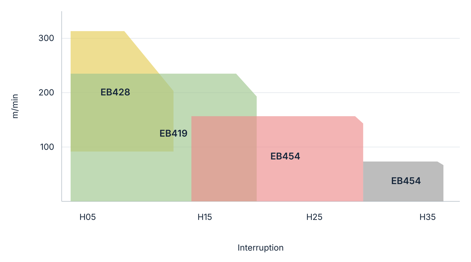
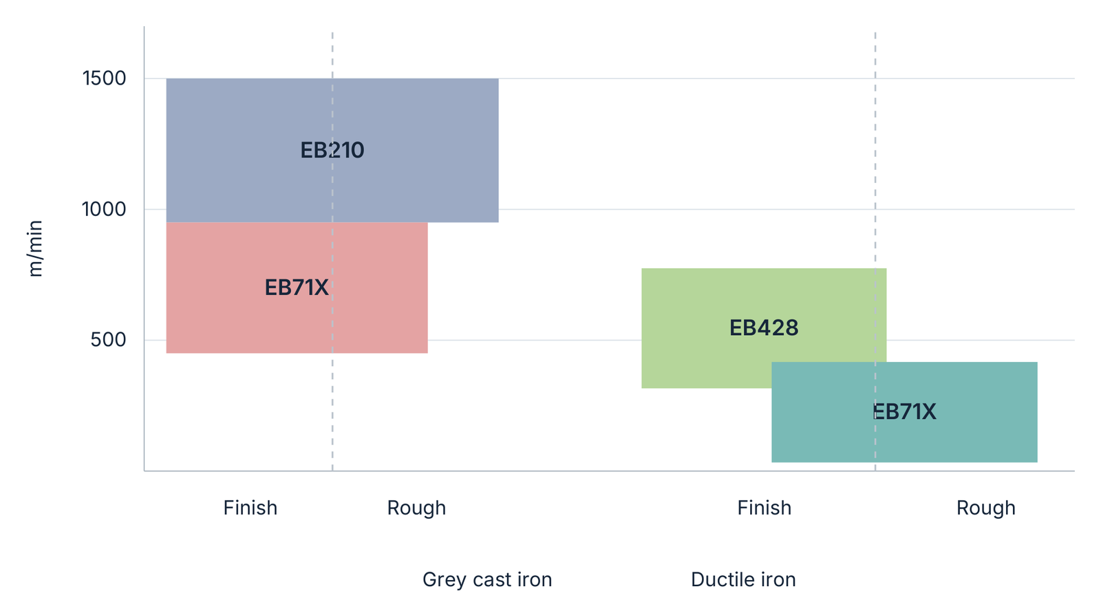
Grade selection links workpiece material, cutting speed and interruption. For hardened steel above HRC 50, the source shows H05, H15, H25 and H35. The supplementary manufacturer's grade guide defines these as continuous cutting, light, medium and heavy interruption. The second selection chart distinguishes grey cast iron and ductile iron, with finishing and roughing applications.
Grade selection for hardened steel above HRC 50: cutting speed in m/min and interruption from H05 to H35. Original region shapes and grade labels are retained.Grade selection for grey cast iron and ductile iron: finishing, roughing and cutting speed in m/min.
Grade
Cutting conditions and benefits stated in the source
EB428
Continuous cutting. Good wear resistance at high temperatures; suitable for heat-treated steel and ductile iron at high speed. The TNP coating improves heat resistance.
EB419
Continuous to medium interrupted cutting. Good wear resistance in heat-treated steel; TNP coating provides high heat resistance.
EB454
Light to heavy interrupted cutting. For heat-treated steel at intermediate to high speed; TNP coating supports heat resistance and edge sharpness.
EB210
Heavy interrupted cutting. The source highlights impact and wear resistance for high-speed machining of high-hardness cast iron.
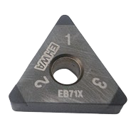
EB71X
High-CBN-content grade for cast iron machining.
Six separate application and comparison examples
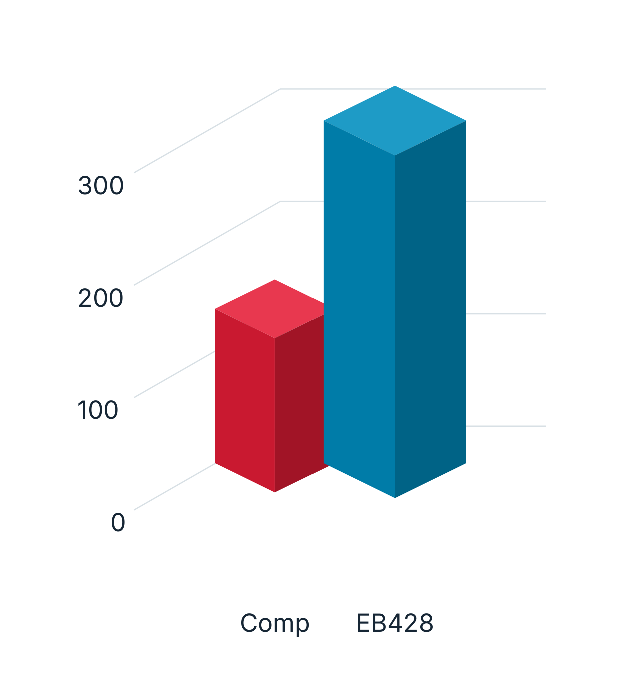
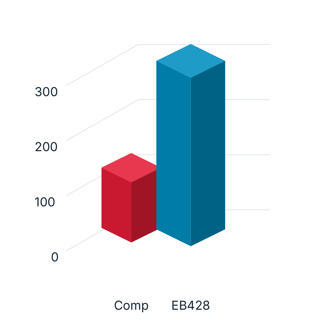
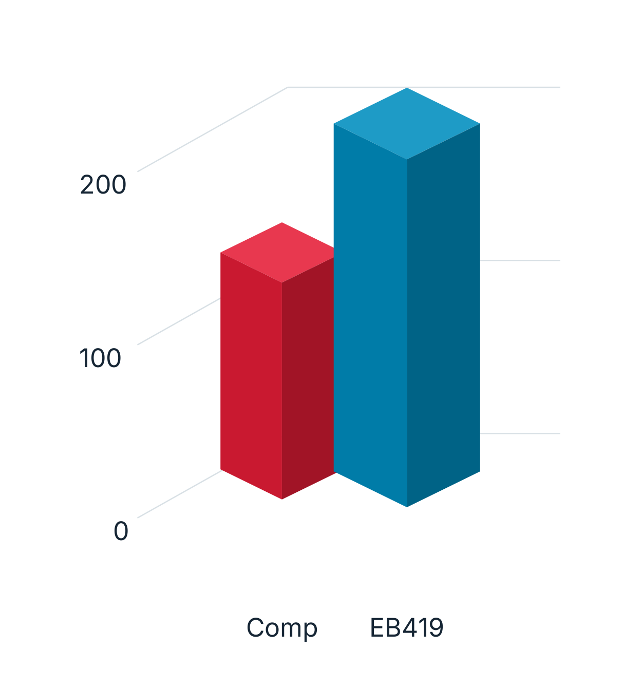
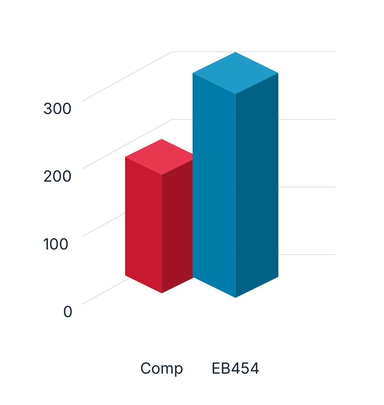
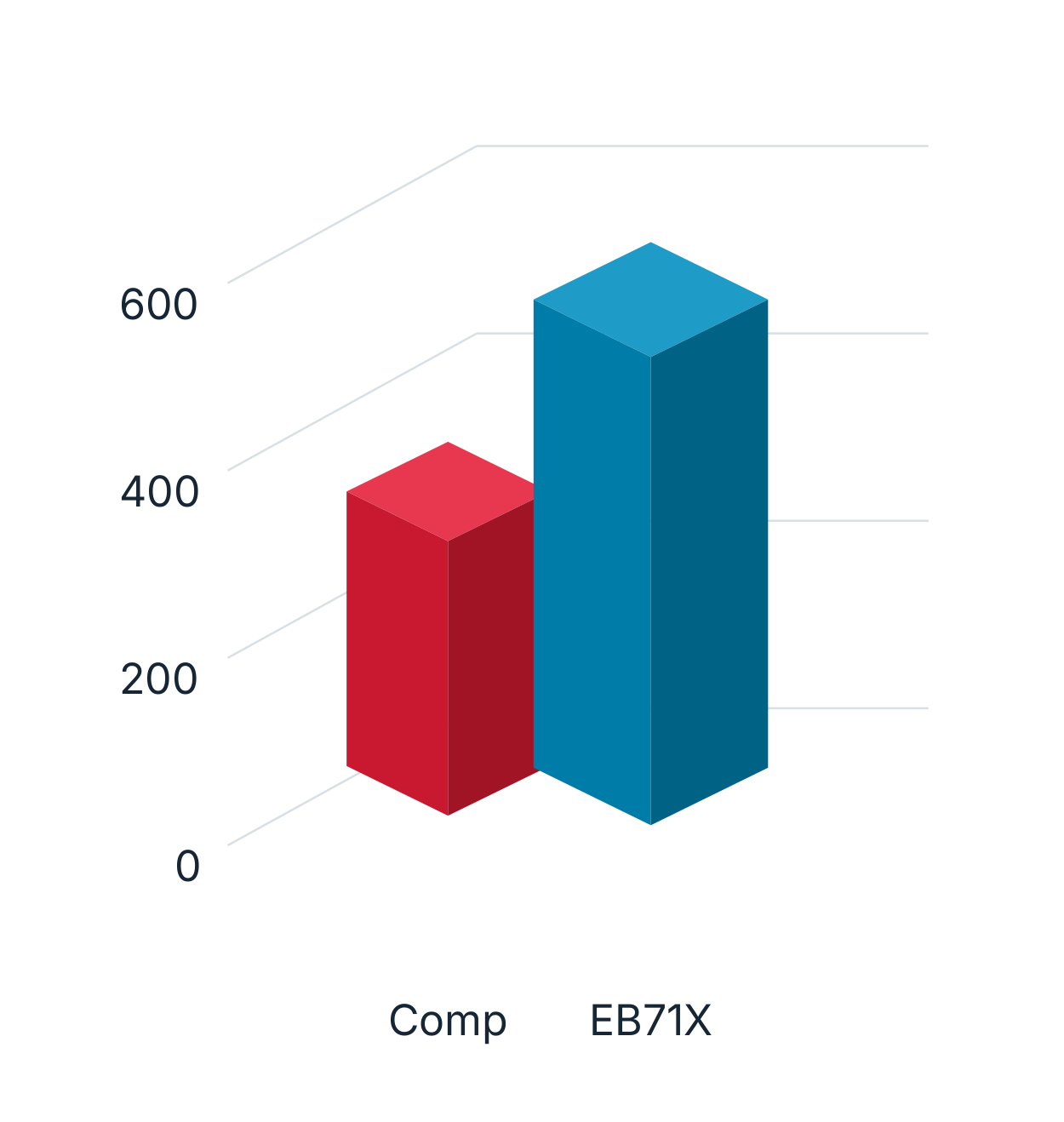
The source illustrates each application with a workpiece, an insert and a comparison with a competitor's tool (Comp). The following six charts remain separate examples. Their axes contain numbers but do not identify the measured quantity or its unit, and complete test conditions are not supplied; no universal tool-life or performance guarantee is derived from them.
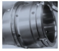
EB428 · SCM415H
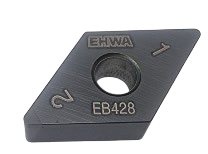
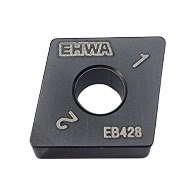
SCM415H workpiece example for EB428.EB428 insert for the SCM415H example.Source comparison of Comp and EB428 with SCM415H; scale marks 0, 100, 200 and 300.
EB428 · FCD500
FCD500 workpiece example for EB428.EB428 insert for the FCD500 example.Source comparison of Comp and EB428 with FCD500; scale marks 0, 100, 200 and 300.
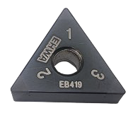
EB419 · SCR420HB
SCR420HB workpiece example for EB419; the material designation is retained as printed.EB419 insert.Source comparison of Comp and EB419; scale marks 0, 100 and 200.
EB454 · SCM415H
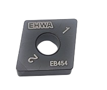
SCM415H workpiece example for EB454.EB454 insert.Source comparison of Comp and EB454; scale marks 0, 100, 200 and 300.
EB210 · CF53
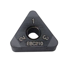
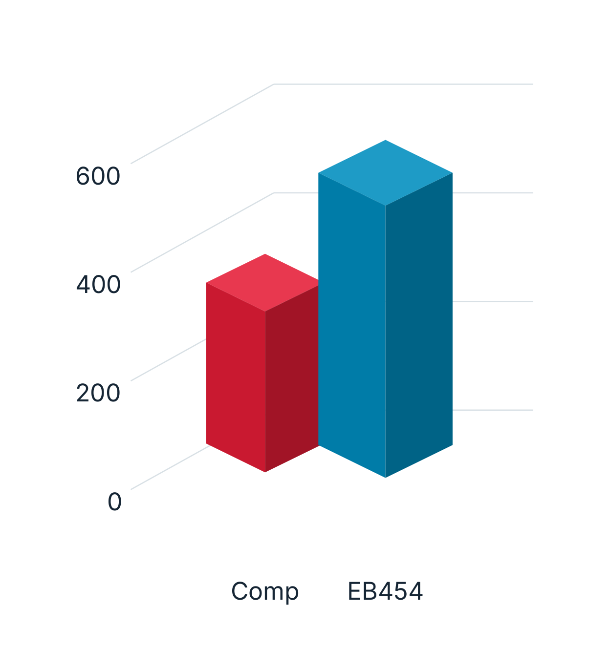
CF53 workpiece example in the EB210 section.Insert with the EBC210 designation visible in the photograph.Comparison in the EB210 section: the original blue legend reads EB454; scale marks 0, 200, 400 and 600.
CF53 is a steel, and EHWA's official grade guide also lists a CF53 test example for EB210. The photograph, the EB210 section heading and the differing EB454 chart legend are therefore identified separately. The blue bar is not reassigned to another grade.
EB71X · FC170
FC170 workpiece example for EB71X.EB71X insert.Source comparison of Comp and EB71X; scale marks 0, 200, 400 and 600.
The source's print note is June 2024. EB454 is shown twice in the steel selection chart; both original labels are retained.
PCD helical endmills: high feeds and small tool designs
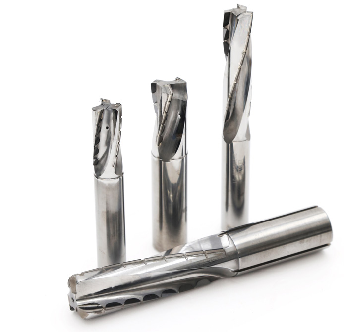
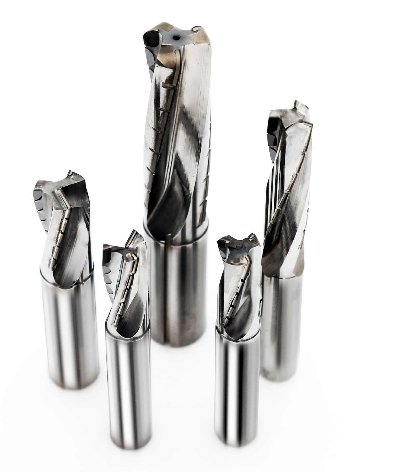
EHWA helical endmills support high-feed machining, high material removal rates and high process reliability. A high rake angle helps to prevent burr formation; the source highlights high speed, efficient machining and good surface finish. The tools combine PCD cutting edges with a tungsten carbide shank. Tool designs and configurations can be adapted to customer requirements.
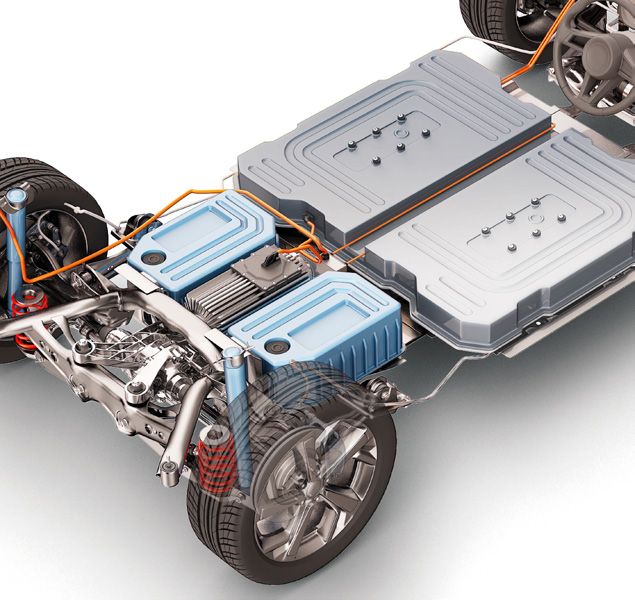
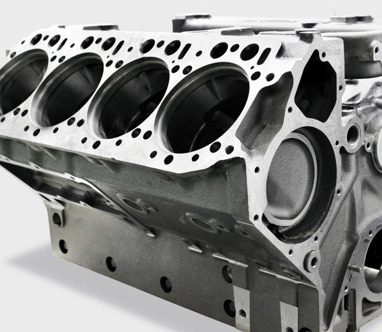
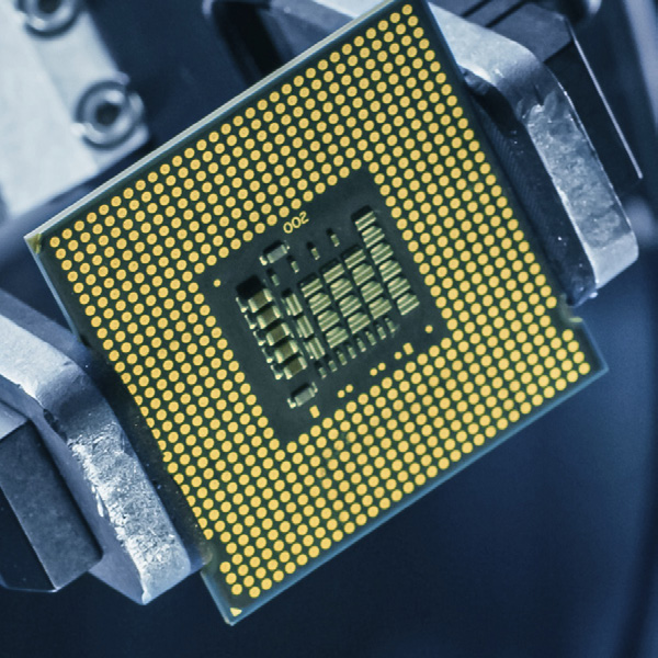
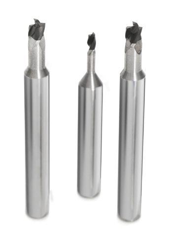
Electric mobility application image.Aircraft application image.Battery component application image.Engine block application image.Electronics application image.PCD helical endmills and small tool designs.Small PCD designs from the cover illustration.Helical endmills with PCD cutting edges and tungsten carbide shanks.
Specifications and tool drawing
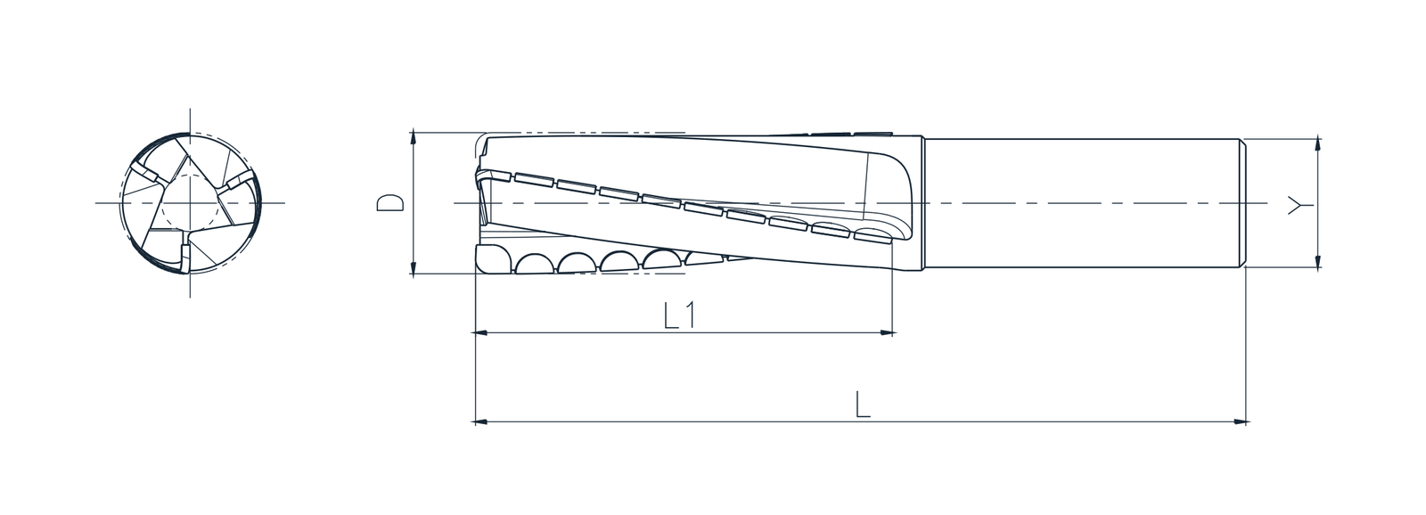
D, Y, L1, L and F retain the source table designations and are linked to the tool drawing.
Item number
D
Y
L1
L
F
EDEH 31616 - 30 -120
16
16
30
120
3
EDEH 32020 - 30 -120
20
20
30
120
3
EDEH 32525 - 30 -120
25
25
30
120
3
EDEH 33032 - 30 -120
30
32
30
120
4
Tool drawing with end and side views: D, Y, L1 and L.
Small PCD tool designs
The source shows four small tools and an enlarged PCD cutting edge. It identifies the smallest design as “2D”; this designation is retained without adding a dimensional unit.
Four small PCD tool designs; source designation for the smallest size: 2D.Enlarged PCD cutting edge of the highlighted small tool.
PCD grades EP20, EP55 and EP59: properties and order list
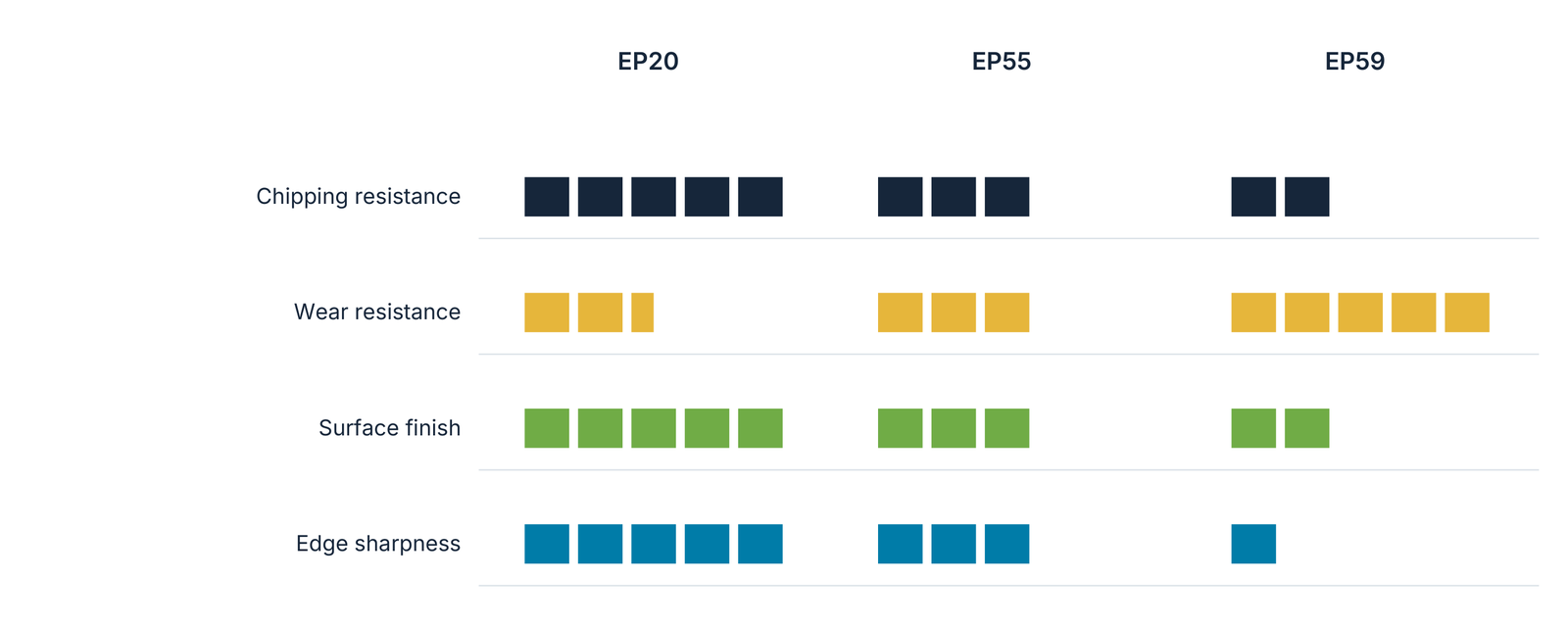
PCD selection links grit size, chipping resistance, wear resistance, surface finish and edge sharpness. The source compares three grades with different priorities.
Grade
Grit size (µm)
Applications
Features and benefits
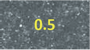
EP20 · Ultra Fine
0.5
Copper alloys, aluminium alloys, acrylic and engineering plastics
Densely packed submicron diamond grains; good wear and impact resistance.
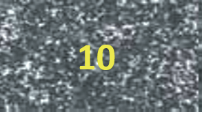
EP55 · Medium
10
Automotive engines, transmissions (T/M), wood, aluminium alloys with Si < 13% and carbon
General-purpose grade for non-ferrous materials.
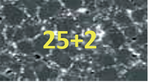
EP59 · Multi Modal
25+2
Aluminium alloys with Si > 13%, tungsten carbide, ceramics, glass and MMC
High diamond content (source statement: over 95%); high wear and impact resistance.
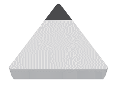
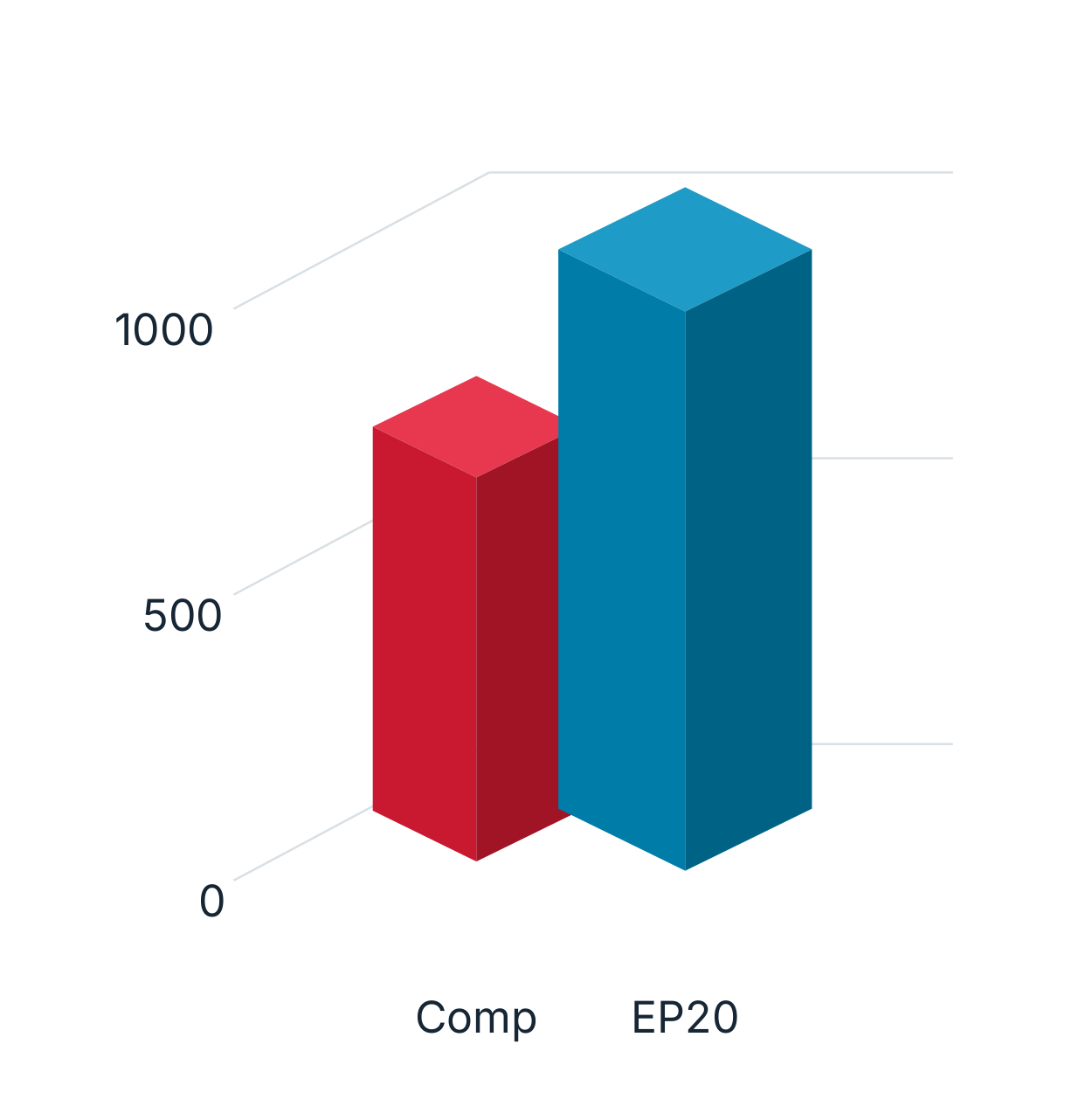
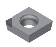
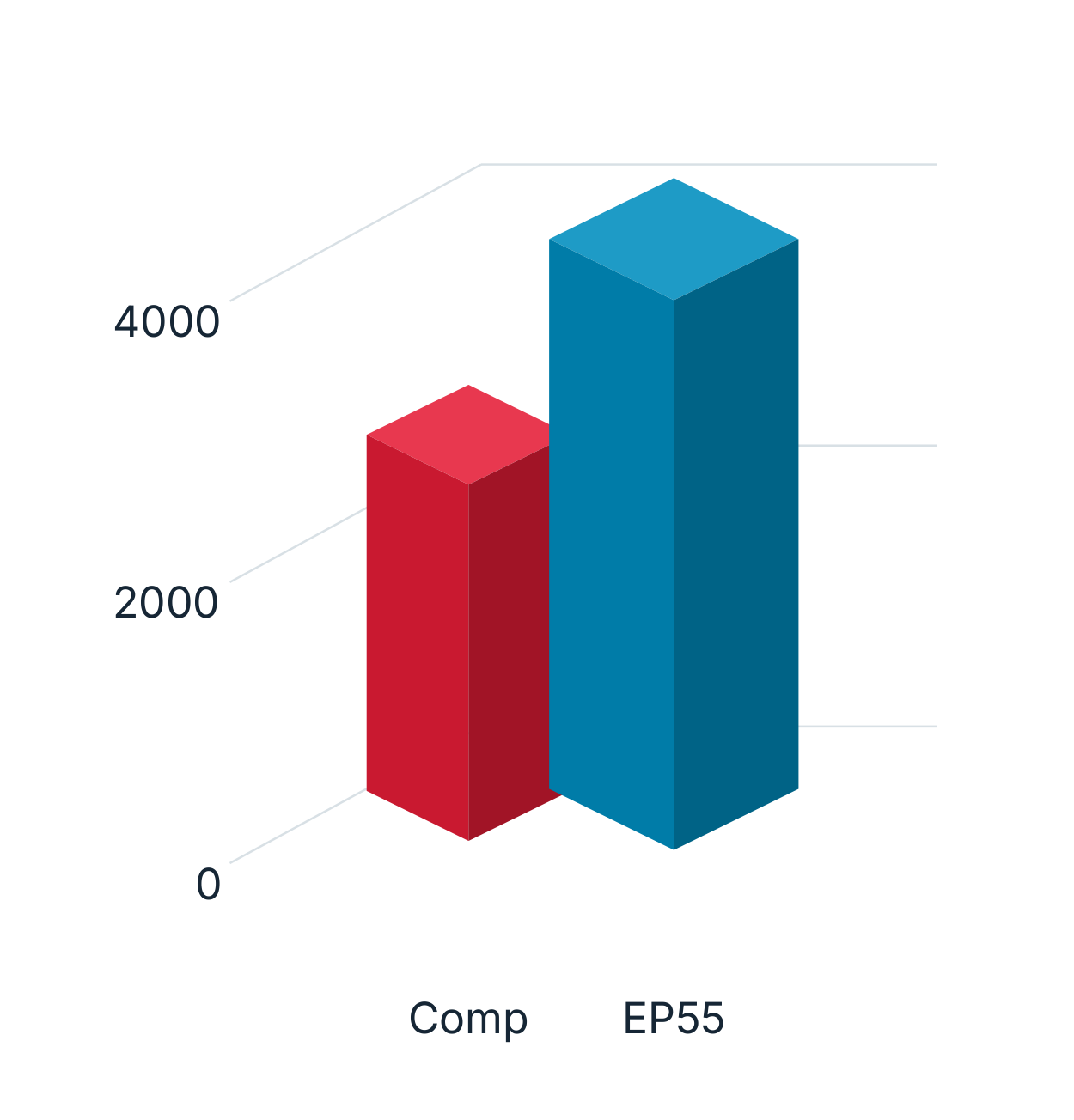
EP20: Microstructure.EP55: Microstructure.EP59: Microstructure.Relative property comparison: original block lengths for chipping resistance, wear resistance, surface finish and edge sharpness; no absolute measurements.EP20: Application illustration.EP20: Workpiece example.EP20: PCD insert.EP20: Comparison of Comp and EP20; the source does not state the measured quantity, its unit or complete conditions.EP55: Application illustration.EP55: Workpiece example.EP55: PCD insert.EP55: Comparison of Comp and EP55; the source does not state the measured quantity, its unit or complete conditions.EP59: Application illustration.EP59: Workpiece example.EP59: PCD insert.EP59: Comparison of Comp and EP59; the source does not state the measured quantity, its unit or complete conditions.
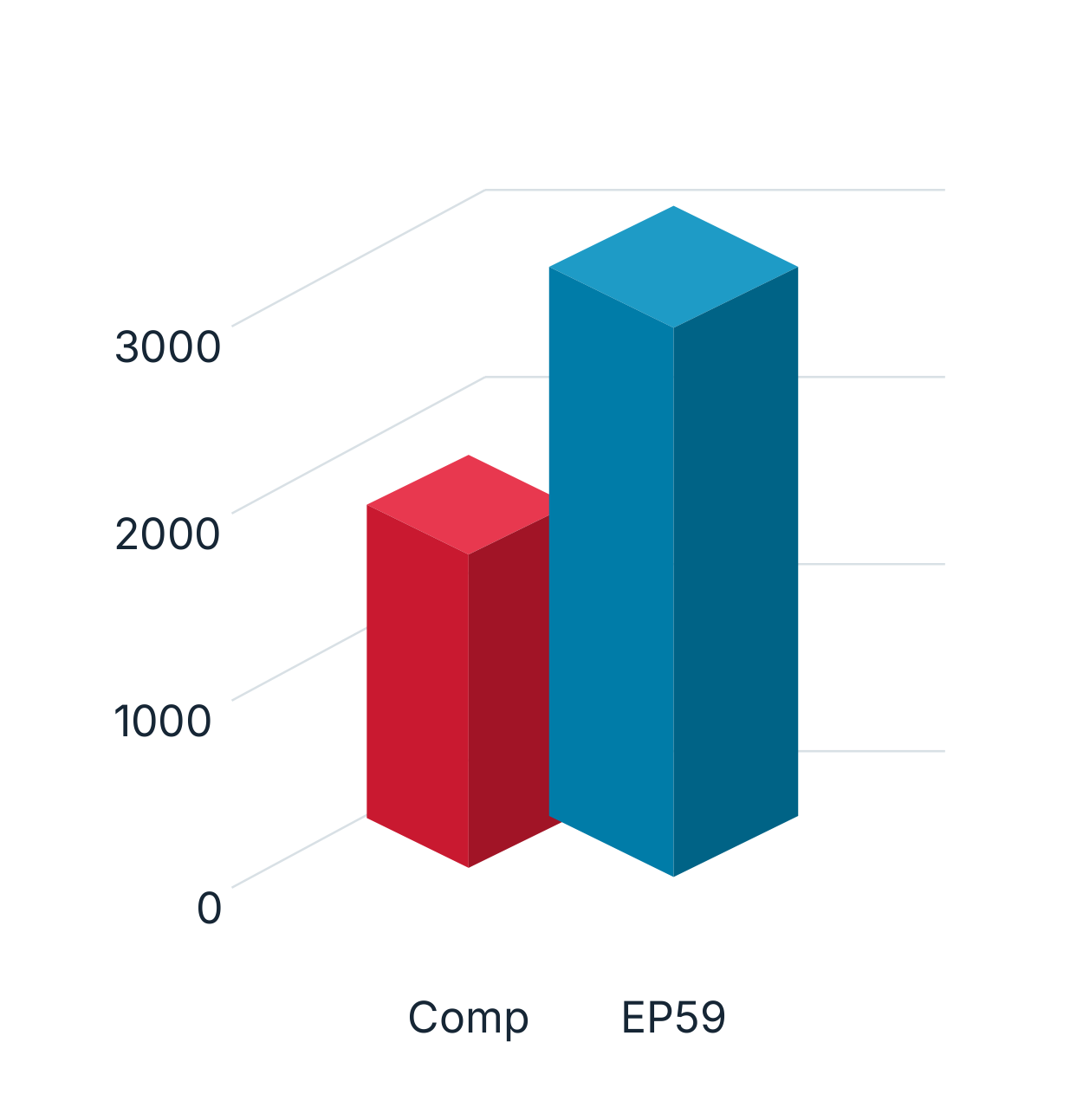
The three comparison charts remain separate: EP20 has scale marks 0/500/1000, EP55 0/2000/4000 and EP59 0/1000/2000/3000. The supplementary EHWA cutting tools catalogue lists a diamond volume fraction of 95% for EP59, while the current short source states “over 95%”. Statements from different editions are not combined into a new specification.
Complete PCD order list
All 20 model groups, each with three rows, are retained. ● and order codes remain in their original grade column; — denotes a blank source cell. The historical stock list supports variant selection; current availability is confirmed with an enquiry.
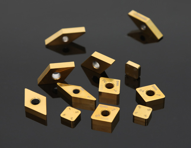
CNGX120404 · TIP 1
PCD CNGX120404: illustrated model shape.
Metric designation
Inch designation
Nose R
EP55
EP20
EP59
CNGX120404
CNGX431
0.4
● EC01C02130120
—
—
08
2
0.8
● EC01C03130100
—
—
12
3
1.2
● EC01C04130120
—
—
CCGT060202 · TIP 1
PCD CCGT060202: illustrated model shape.
Metric designation
Inch designation
Nose R
EP55
EP20
EP59
CCGT060202
CCGT2(1.5)0.5
0.2
● EC01C06130110
● EC01C06070110
—
04
1
0.4
● EC01C07130110
● EC01C07070110
—
08
2
0.8
● EC01C08130110
—
—
CCGT09T302 · TIP 1
PCD CCGT09T302: illustrated model shape.
Metric designation
Inch designation
Nose R
EP55
EP20
EP59
CCGT09T302
CCGT3(2.5)0.5
0.2
● EC01C10130110
● EC01C10070110
—
04
1
0.4
● EC01C11130110
● EC01C11070110
—
08
2
0.8
● EC01C12130110
● EC01C12070110
—
DNGX150404 · TIP 1
PCD DNGX150404: illustrated model shape.
Metric designation
Inch designation
Nose R
EP55
EP20
EP59
DNGX150404
DNGX431
0.4
● EC01D05130120
—
—
08
2
0.8
● EC01D06130120
—
—
12
3
1.2
● EC01D07130120
—
—
DCGT070202 · TIP 1
PCD DCGT070202: illustrated model shape.
Metric designation
Inch designation
Nose R
EP55
EP20
EP59
DCGT070202
DCGT2(1.5)0.5
0.2
● EC01D09130110
● EC01D09070110
—
04
1
0.4
● EC01D10130110
● EC01D10070110
—
08
2
0.8
● EC01D11130110
● EC01D11070110
—
DCGT11T302 · TIP 1
PCD DCGT11T302: illustrated model shape.
Metric designation
Inch designation
Nose R
EP55
EP20
EP59
DCGT11T302
DCGT3(2.5)0.5
0.2
● EC01D13130110
● EC01D13070110
—
04
1
0.4
● EC01D14130110
● EC01D14070110
—
08
2
0.8
● EC01D15130110
● EC01D15070110
—
TNGX160402 · TIP 1
PCD TNGX160402: illustrated model shape.
Metric designation
Inch designation
Nose R
EP55
EP20
EP59
TNGX160402
TNGX430.5
0.2
● EC01T04130120
—
—
04
1
0.4
● EC01T05130120
—
—
08
2
0.8
● EC01T06130120
—
—
TCGT090202 · TIP 1
PCD TCGT090202: illustrated model shape.
Metric designation
Inch designation
Nose R
EP55
EP20
EP59
TCGT090202
TCGT2(1.5)0.5
0.2
● EC01T19130110
—
—
04
1
0.4
● EC01T20130110
—
—
08
2
0.8
● EC01T21130110
—
—
TCGT110202 · TIP 1
PCD TCGT110202: illustrated model shape.
Metric designation
Inch designation
Nose R
EP55
EP20
EP59
TCGT110202
TCGT3(1.5)0.5
0.2
● EC01T23130110
—
—
04
1
0.4
● EC01T24130110
—
—
08
2
0.8
● EC01T25130110
—
—
TCGT110302 · TIP 1
PCD TCGT110302: illustrated model shape.
Metric designation
Inch designation
Nose R
EP55
EP20
EP59
TCGT110302
TCGT320.5
0.2
● EC01T75130110
—
—
04
1
0.4
● EC01T76130110
—
—
08
2
0.8
● EC01T77130110
—
—
TCGT16T302 · TIP 1
PCD TCGT16T302: illustrated model shape.
Metric designation
Inch designation
Nose R
EP55
EP20
EP59
TCGT16T302
TCGT4(2.5)0.5
0.2
● EC01T26130110
—
—
04
1
0.4
● EC01T27130110
—
—
08
2
0.8
● EC01T28130110
—
—
TPGT080202 · TIP 1
PCD TPGT080202: illustrated model shape.
Metric designation
Inch designation
Nose R
EP55
EP20
EP59
TPGT080202
TPGT1.5(1.5)0.5
0.2
● EC01T31130110
—
—
04
1
0.4
● EC01T32130110
—
—
08
2
0.8
● EC01T33130110
—
—
TPGT090202 · TIP 1
PCD TPGT090202: illustrated model shape.
Metric designation
Inch designation
Nose R
EP55
EP20
EP59
TPGT090202
TPGT2(1.5)0.5
0.2
● EC01T35130110
—
—
04
1
0.4
● EC01T36130110
—
—
08
2
0.8
● EC01T37130110
—
—
TPGT110202 · TIP 1
PCD TPGT110202: illustrated model shape.
Metric designation
Inch designation
Nose R
EP55
EP20
EP59
TPGT110202
TPGT3(1.5)0.5
0.2
● EC01T39130110
—
—
04
1
0.4
● EC01T40130110
—
—
08
2
0.8
● EC01T41130110
—
—
TPGT110302 · TIP 1
PCD TPGT110302: illustrated model shape.
Metric designation
Inch designation
Nose R
EP55
EP20
EP59
TPGT110302
TPGT320.5
0.2
● EC01T43130110
—
—
04
1
0.4
● EC01T44130110
—
—
08
2
0.8
● EC01T45130110
—
—
VNGX160402 · TIP 1
PCD VNGX160402: illustrated model shape.
Metric designation
Inch designation
Nose R
EP55
EP20
EP59
VNGX160402
VNGA430.5
0.2
● EC01V01130120
—
—
04
1
0.4
● EC01V02130120
—
—
08
2
0.8
● EC01V03130120
—
—
VBGT110302 · TIP 1
PCD VBGT110302: illustrated model shape.
Metric designation
Inch designation
Nose R
EP55
EP20
EP59
VBGT110302
VBGW320.5
0.2
● EC01V05130110
● EC01V05070110
—
04
1
0.4
● EC01V06130110
● EC01V06070110
—
08
2
0.8
● EC01V07130110
● EC01V07070110
—
VBGT160402 · TIP 1
PCD VBGT160402: illustrated model shape.
Metric designation
Inch designation
Nose R
EP55
EP20
EP59
VBGT160402
VBGT430.5
0.2
● EC01V08130110
● EC01V08070110
—
04
1
0.4
● EC01V09130110
● EC01V09070110
● EC01V09150110
08
2
0.8
● EC01V10130110
● EC01V10070110
● EC01V10150110
VCGT110302 · TIP 1
PCD VCGT110302: illustrated model shape.
Metric designation
Inch designation
Nose R
EP55
EP20
EP59
VCGT110302
VCGT320.5
0.2
● EC01V12130110
● EC01V12070110
—
04
1
0.4
● EC01V13130110
● EC01V13070110
—
08
2
0.8
● EC01V15130110
● EC01V15070110
—
VCGT160404 · TIP 1
PCD VCGT160404: illustrated model shape.
Metric designation
Inch designation
Nose R
EP55
EP20
EP59
VCGT160404
VCGW431
0.4
● EC01V16130110
● EC01V16070110
● EC01V16150110
08
2
0.8
● EC01V17130110
● EC01V17070110
● EC01V17150110
12
3
1.2
● EC01V18130110
● EC01V18070110
● EC01V18150110
Differing printed inch designations such as VNGX160402/VNGA430.5 and VCGT160404/VCGW431 are also retained unchanged. The source print note is June 2024.
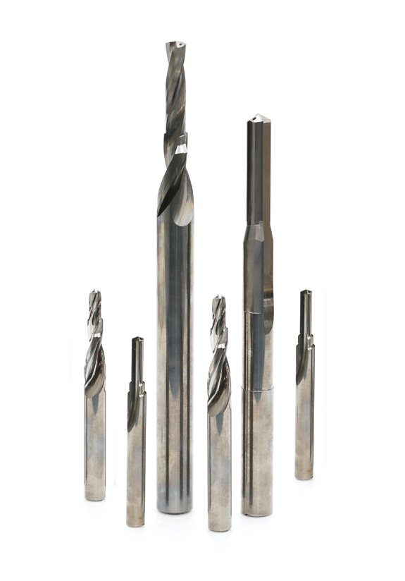
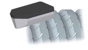
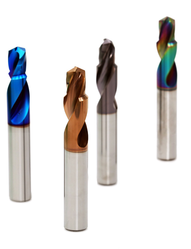
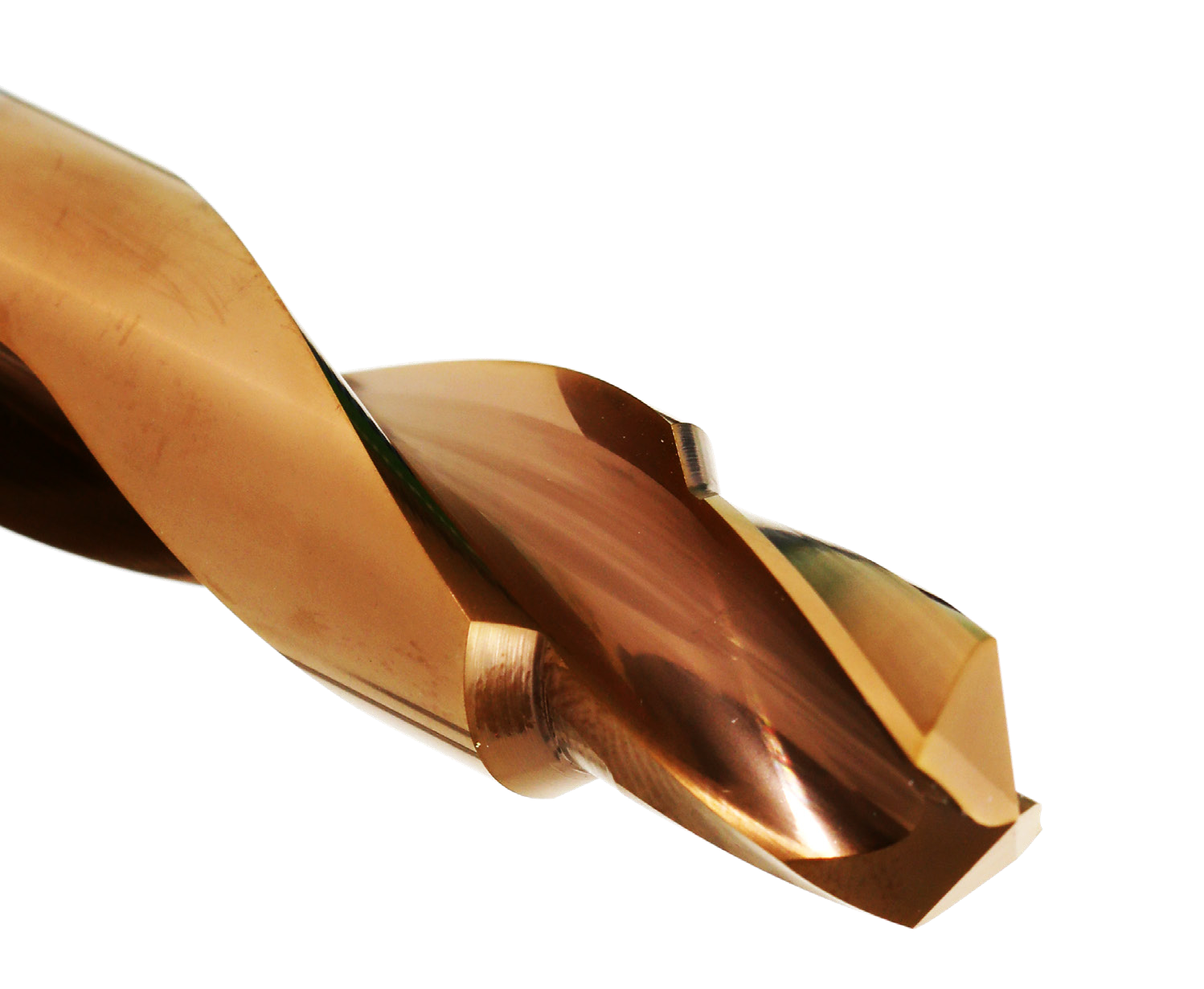
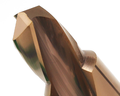
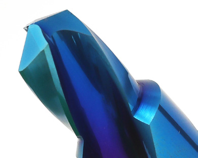
ET220 is an ultra-fine carbide material combining high hardness with high fracture toughness. The helical drills for steel have two to three coolant holes. The helix angle is 30°, and the flute shape supports fluent chip flow. The coating combines toughness with wear resistance.
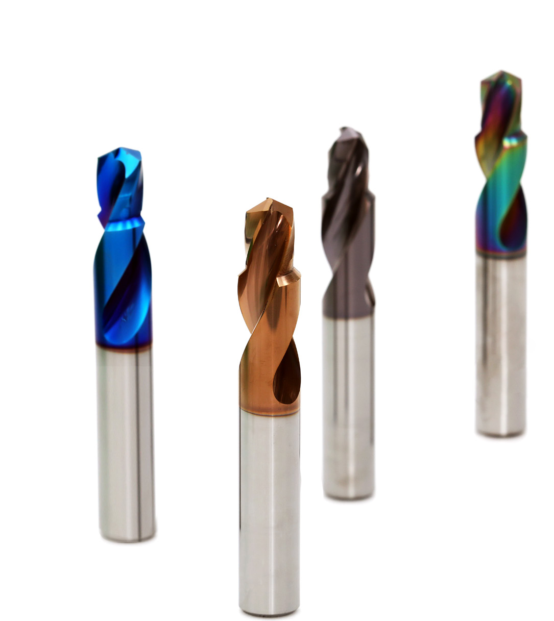
Four coated solid carbide drills; introduced as a new product in the source.ET220 drill: 30° helix angle and flute geometry for fluent chip flow.ET220 tools with a tough, wear-resistant coating.
EHWA coatings
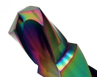
The source presents TA as the conventional coating and H1, H2 and H3 as new coatings for interrupted cutting. The product photographs show the different designs; coating data are given in the EHWA coatings chapter.
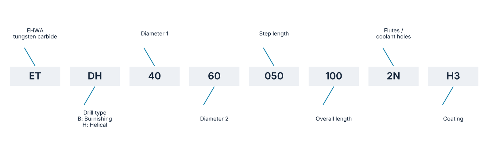
The source example is ET DH 40 60 050 100 2N H3. ET identifies EHWA tungsten carbide, and DH identifies a helical drill. In the drill-type field, B means Burnishing and H means Helical. The remaining fields identify diameter 1, diameter 2, step length, overall length, flute/coolant-hole configuration and coating type.
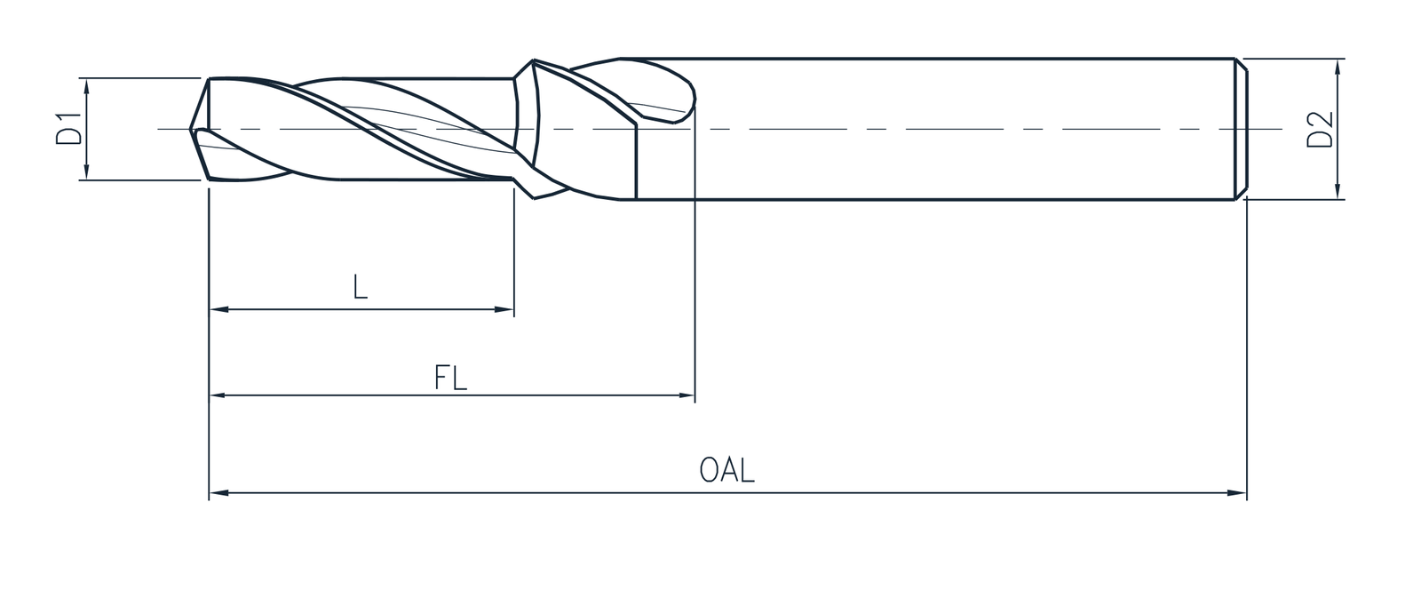
Ordering code with field assignments, including the H3 coating.Drill drawing with D1, D2, L, FL and OAL.
Item code
D1
D2
L
FL
OAL
ETDH 43 60 025 080 2N
4.3
6.0
25
40
80
ETDH 51 80 025 080 2N
5.1
8.0
25
40
80
ETDH 69 100 030 100 2N
6.9
10.0
30
50
100
ETDH 86 120 035 105 2N
8.6
12.0
35
55
105
ETDH 104 140 040 110 2N
10.4
14.0
40
60
110
ETDH 140 160 040 110 2N
14.0
16.0
40
60
110
The table fields correspond to the dimensional drawing. ET220 helical drills and the previously described ET110 burnishing drills remain separate product families; similar size ranges do not replace grade or geometry selection. The source print note is June 2024.
Solid HBN: cutting material series for cast iron roughing
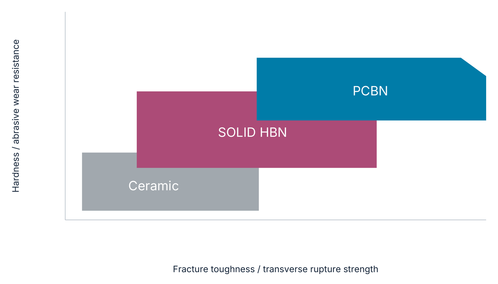
HBN here identifies EHWA’s cutting material series, a PCBN type produced by a special manufacturing method. The source positions it as offering greater wear resistance and hardness than ceramic, and as a more economical alternative to the compared PCBN designs. It highlights performance in cast iron roughing.
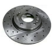
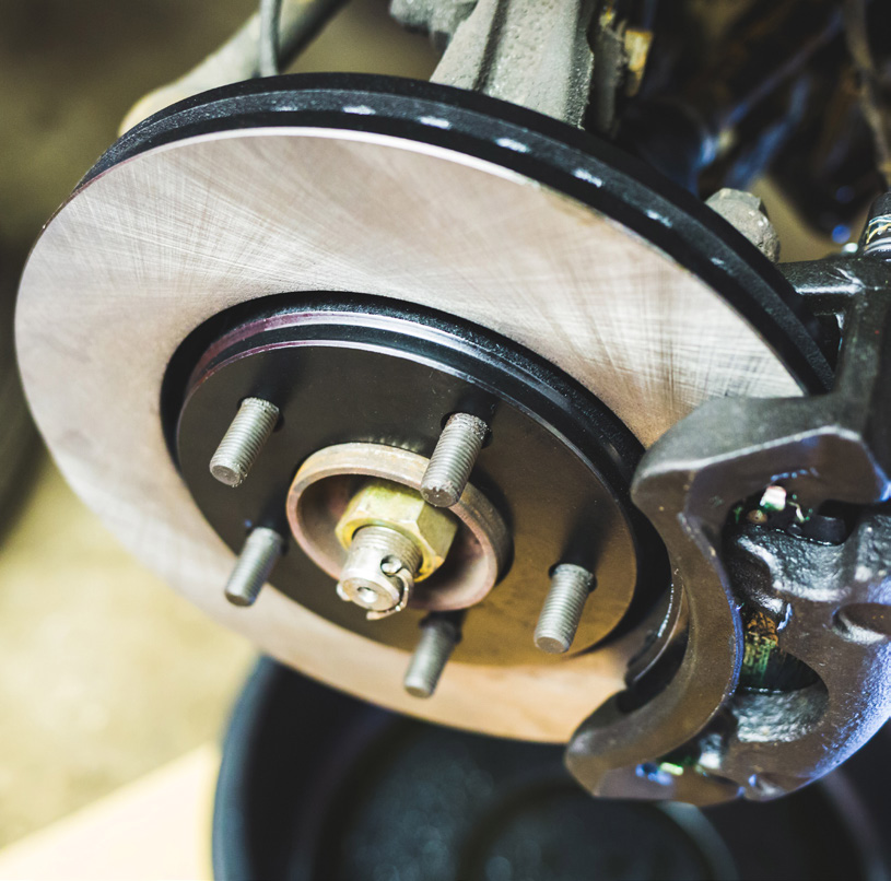
Qualitative positioning of ceramic, Solid HBN and PCBN: hardness/abrasive wear resistance versus fracture toughness/transverse rupture strength. The regions contain no absolute measurements.Brake disc application image.
Four HBN grades
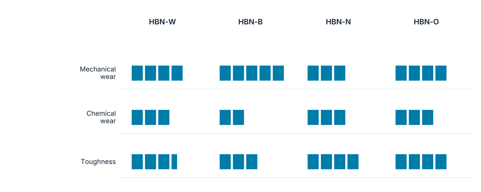
The table retains all grade names, grit sizes and CBN volume fractions. The graphical property comparisons for mechanical wear, chemical wear and toughness remain relative source comparisons.
Grade
Grit size (µm)
CBN volume fraction
Characteristics
HBN-W
10
85–90 %
Standard grade for grey cast iron
HBN-B
20
85–90 %
Improved wear resistance
HBN-N
4
90–95 %
Improved surface finish
HBN-O
6+12
85–90 %
Improved wear resistance and toughness
Original relative property comparison: HBN-W/HBN-B/HBN-N/HBN-O. Block counts and partial block lengths are retained; the source does not state an absolute measurement scale.
Workpiece material and hardness, component drawing, machining operation, tool interface and machine provide the starting point. Existing cutting conditions, interruption, coolant supply and the required surface quality support the choice of grade, cutting geometry and coating. For inserts, start with the model and order code; for custom tools, add the required shape and dimensions.