Profile accuracy and stable dressing performance in creep-feed grinding
Match the workpiece profile and rotary dresser
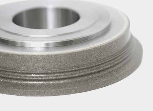
EHWA develops rotary dressers around your workpiece contour. They profile the grinding wheel for subsequent turbine-blade machining. The programme combines custom geometry, high precision, long tool life and stable dressing performance in creep-feed grinding.
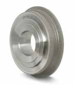
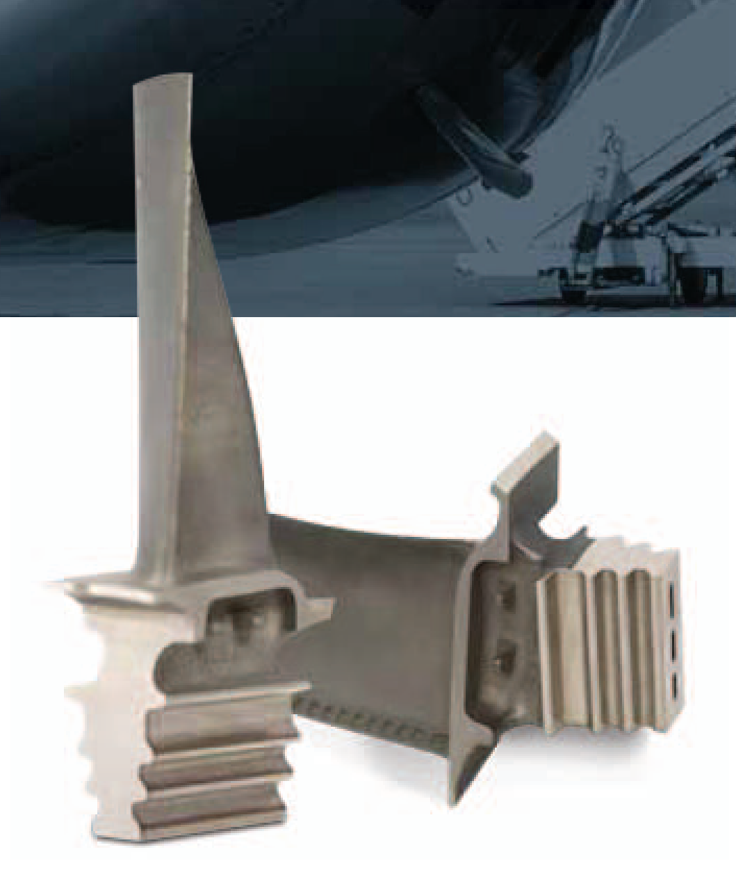
Turbine blades for three application sectors
| Sector | Profile-machining application |
|---|---|
| Aerospace | Blades for aerospace turbines |
| Power generation | Blades for power-generation turbines |
| Shipbuilding | Blades for marine turbines |
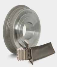
The design is matched to the blade profile and grinding-wheel contour. The photographs show turbine and aircraft-engine applications.
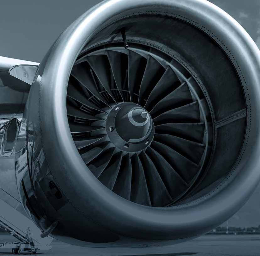
Custom roll design and precise profiling
EHWA identifies three connected benefits:
| Tool feature | Application benefit |
|---|---|
| Roll design based on the workpiece | Match the dressing contour to the blade profile |
| Long tool life and high tool precision | Consider useful life and precise profile machining together |
| Stable dressing performance in creep-feed grinding | Support consistent profiling during the creep-feed grinding process |
Contour, grinding wheel, mounting and dressing strategy are designed together. Drawings and inspection records help match profile quality, surface requirements and dressing intervals.
Four profile-contact arrangements
Four contact positions illustrate profile machining. Blue shows the upper profile; grey shows the blade/counterprofile. The arrangement is matched to your workpiece drawing.
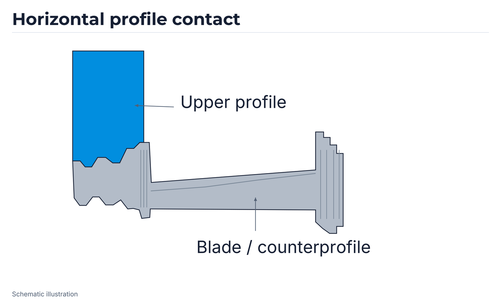
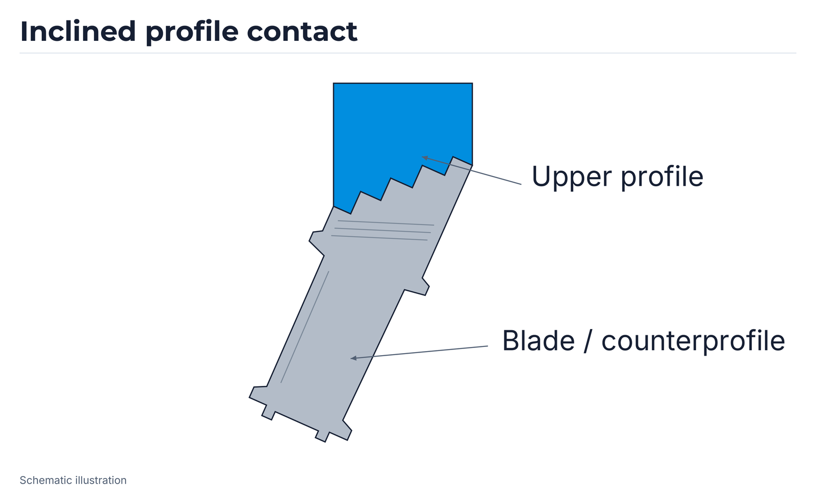
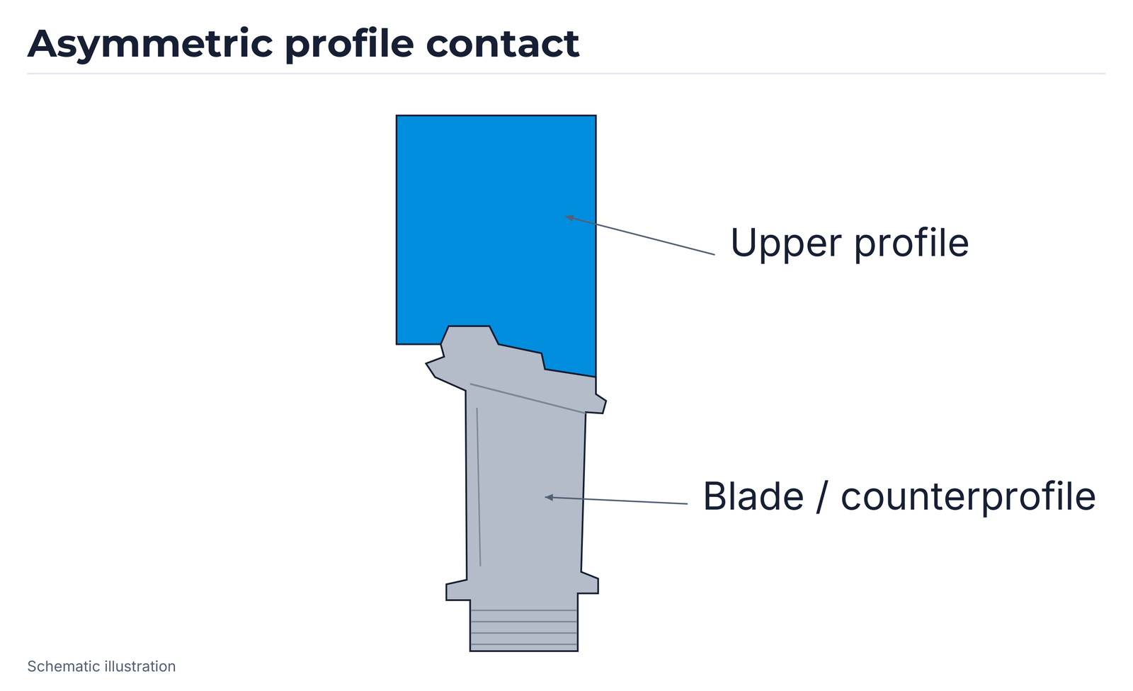
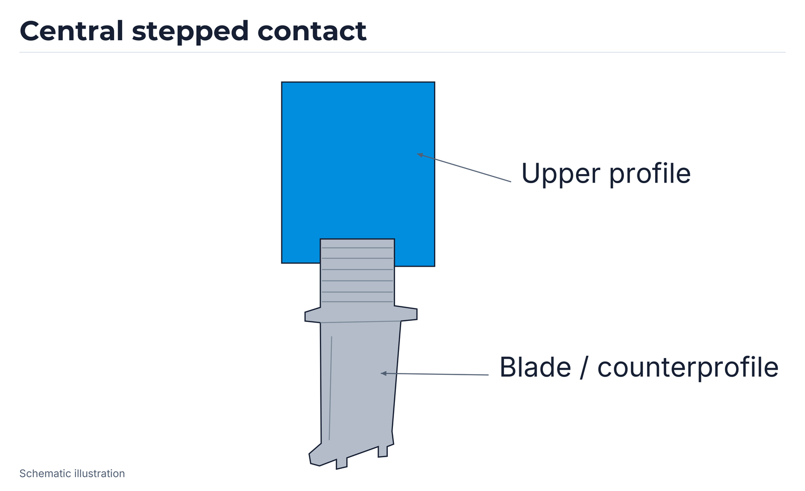
Profile dimensions, radii and contact positions follow your component and tool drawings.
Discuss your turbine application
Provide the blade drawing, material, machine, mounting and grinding wheel. Add your existing rotary dresser, dressing strategy and required profile and surface quality. Inspection records, wear patterns and dressing intervals support the comparison. Together, we match the design to your production process.
EHWA Europe: info@ehwadia.de · +49 6173 997780
Editorial edition: 13 October 2026. Technical basis: EHWA, Turbine.