Helical ceramic tools for heat-resistant superalloys
Tools for demanding turbine and engine components
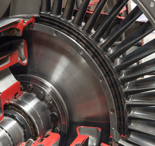
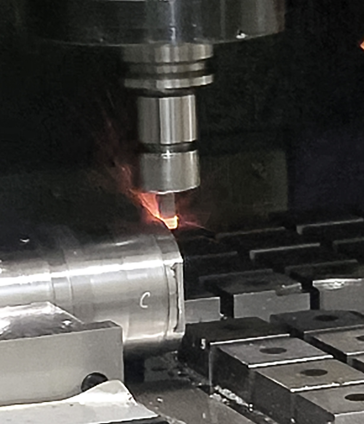
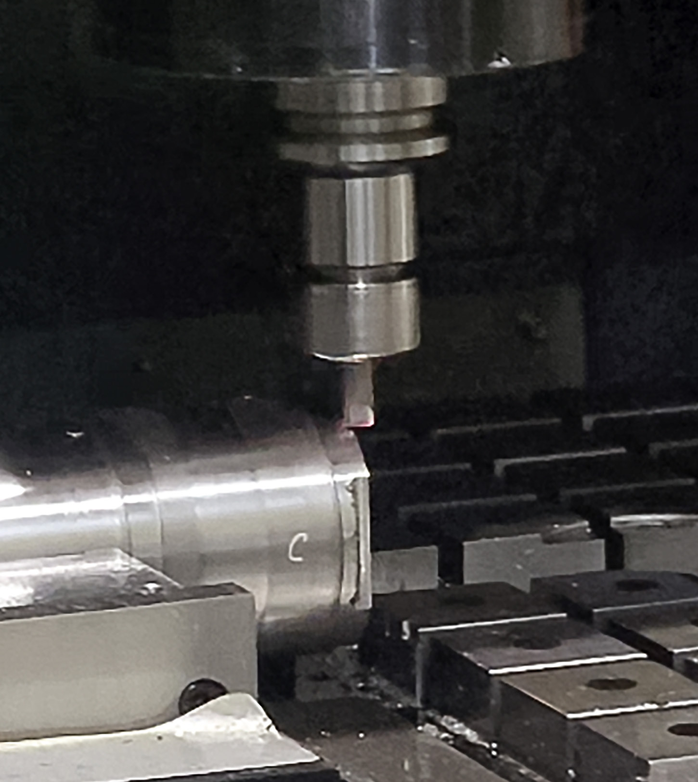
Heat-resistant superalloys (HRSA) combine high temperature resistance with requirements for functionality, low component weight, durability and efficiency. They are used in aerospace and automotive applications, among others. Nickel alloys such as Inconel are typical materials for turbines and jet engines; their heat resistance also makes them demanding to machine. EHWA has developed helical ceramic end mills for these applications.
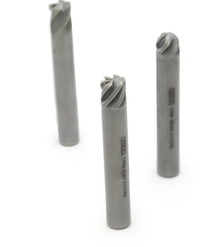
The complete range comprises square end mills with a corner radius and four or six flutes, together with five-flute ball end mills. Grade EC2008 uses SiAlON ceramic. Tool geometry, mounting interface and cutting conditions are selected for the particular HRSA component.
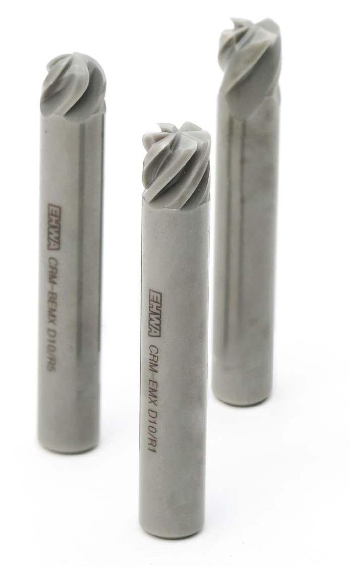
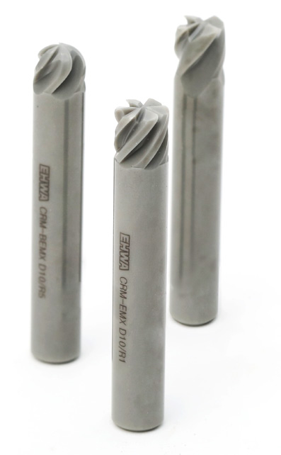




EC2008: SiAlON ceramic and thermal properties
| Feature | EHWA specification |
|---|---|
| Grade | EC2008 |
| Material | SiAlON |
| Colour | Dark Olive Green |
| Workpiece material | HRSA (Heat-Resistant Super Alloy) |
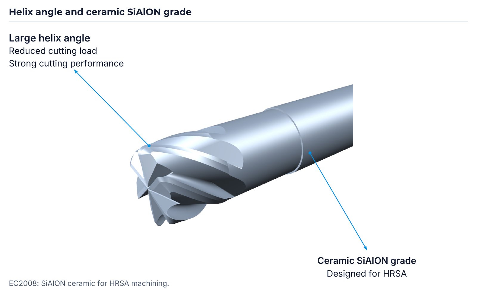
SiAlON ceramics are based on silicon (Si), aluminium (Al), oxygen (O) and nitrogen (N). The EHWA material description highlights high heat resistance and low thermal conductivity. These thermal properties support tool selection for demanding machining conditions involving high temperatures and pressure loads, such as turbine and automotive-engine components.
EC2008 is designed for HRSA machining. The large helix angle is intended to reduce cutting load and provide strong cutting performance. The thermal design is matched to the tool and process.
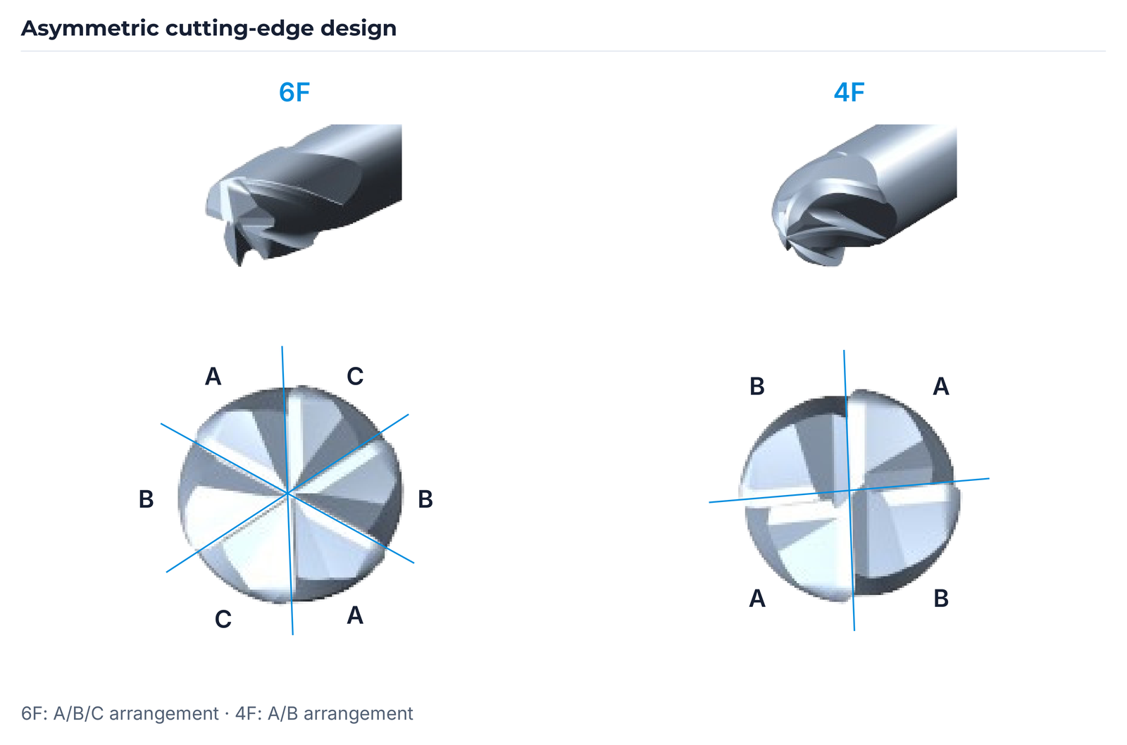
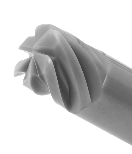
Asymmetric cutting-edge design
The asymmetric cutting-edge design is illustrated for six and four flutes. Perspective and end views show the respective arrangement: A/B/C for 6F and A/B for 4F.
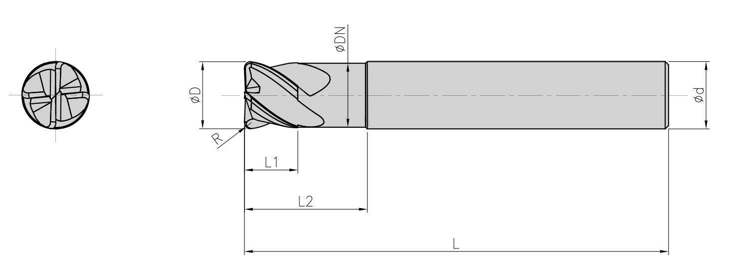
Item code and dimensional designations
The item code combines material, design and tool dimensions. Example EC ER 100 100 – 080 650 – 10 6F explains its designation blocks.
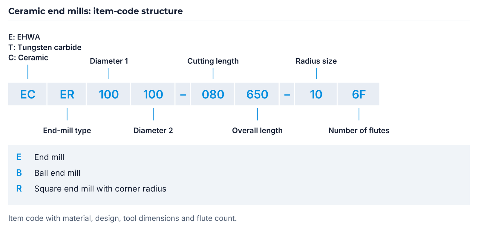
In the manufacturer/material block, E denotes EHWA, T tungsten carbide and C ceramic. In the design block, E denotes an end mill, B a ball end mill and R a square end mill with a corner radius. The remaining blocks identify diameter 1, diameter 2, cutting length, overall length, radius size and number of flutes.
| Designation | Meaning |
|---|---|
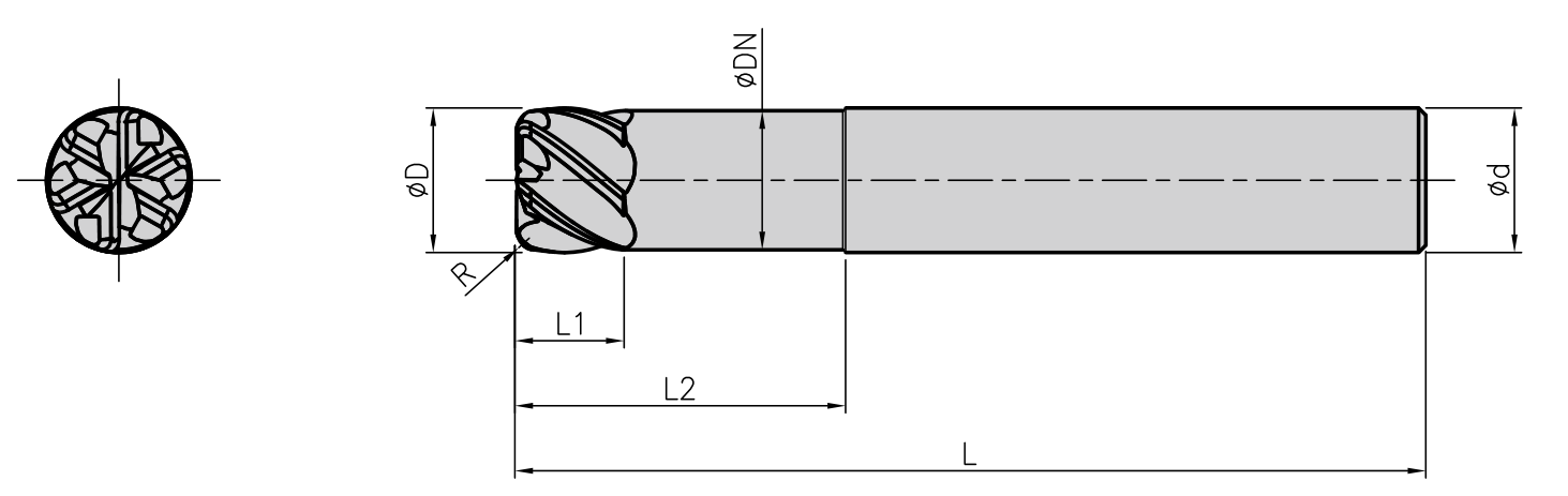
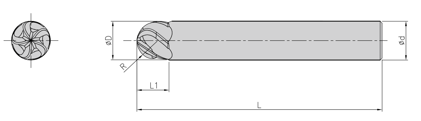
| D | Cutting diameter |
| d | Shank diameter |
| L | Overall length |
| L1 | Cutting length |
| L2 | Length to the shank transition |
| DN | Neck diameter |
| R | Corner radius or ball radius of the relevant design |
The manufacturer dimension tables do not specify a general unit. Dimensional definitions, units and binding tool dimensions are confirmed against the drawing.

Four flutes: square end mills with corner radius
Six standard versions are available with the following tool dimensions.

| Item code | D | d | L | L1 | L2 | DN | R |
|---|---|---|---|---|---|---|---|
| ECER 060060 060600 05 4F | 6 | 6 | 60 | 6 | 12 | 5.8 | 0.5 |
| ECER 080080 060600 10 4F | 8 | 8 | 60 | 6 | 15 | 7.7 | 1.0 |
| ECER 100100 080650 10 4F | 10 | 10 | 65 | 8 | 20 | 9.7 | 1.0 |
| ECER 120120 100700 15 4F | 12 | 12 | 70 | 10 | 25 | 11.5 | 1.5 |
| ECER 160160 120830 20 4F | 16 | 16 | 83 | 12 | 30 | 15.5 | 2.0 |
| ECER 200200 150930 20 4F | 20 | 20 | 93 | 15 | 35 | 19.5 | 2.0 |
EHWA Standard Square Endmills: R denotes the corner radius of the respective version.
Six flutes: square end mills with corner radius
Six standard versions are available with the following tool dimensions.
| Item code | D | d | L | L1 | L2 | DN | R |
|---|---|---|---|---|---|---|---|
| ECER 060060 060600 05 6F | 6 | 6 | 60 | 6 | 12 | 5.8 | 0.5 |
| ECER 080080 060600 10 6F | 8 | 8 | 60 | 6 | 15 | 7.7 | 1.0 |
| ECER 100100 080650 10 6F | 10 | 10 | 65 | 8 | 20 | 9.7 | 1.0 |
| ECER 120120 100700 15 6F | 12 | 12 | 70 | 10 | 25 | 11.5 | 1.5 |
| ECER 160160 120830 20 6F | 16 | 16 | 83 | 12 | 30 | 15.5 | 2.0 |
| ECER 200200 150930 20 6F | 20 | 20 | 93 | 15 | 35 | 19.5 | 2.0 |
EHWA Standard Square Endmills: R denotes the corner radius of the respective version.
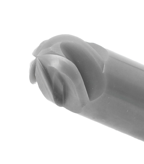
BALL: five-flute ball end mills
Six standard versions are available with the following tool dimensions.
| Item code | D | d | L | L1 | R |
|---|---|---|---|---|---|
| ECEB 060060 060600 30 5F | 6 | 6 | 60 | 6 | 3.0 |
| ECEB 080080 060600 40 5F | 8 | 8 | 60 | 6 | 4.0 |
| ECEB 100100 080650 50 5F | 10 | 10 | 65 | 8 | 5.0 |
| ECEB 120120 100700 60 5F | 12 | 12 | 70 | 10 | 6.0 |
| ECEB 160160 120830 80 5F | 16 | 16 | 83 | 12 | 8.0 |
| ECEB 200200 150930 100 5F | 20 | 20 | 93 | 15 | 10.0 |
EHWA Standard Ball Endmills: the ball end mills have five flutes (5F); R denotes the ball radius.
Adapt flute count and head shape
Flute count and head shape can be adapted. The standard range provides a starting point for the appropriate design. Discuss component geometry, HRSA material, engagement conditions, machine and mounting interface with EHWA Europe to coordinate tool selection.
Select the ceramic tool for your machining process
Specify the component material and condition, machining operation, required geometry and surface, and existing cutting data. Add tool diameter, corner or ball radius, required reach, flute count, machine and mounting interface. EHWA Europe supports selection from the standard range and application-specific modifications.
Technical enquiry to EHWA Europe · Telephone +49 6173 99778-0
Technical basis
EHWA, CERAMIC ENDMILLS, Q250, pages 1–4; manufacturer print date 06/2024. Editorial date of the new German and English editions: 13 October 2026.
General context for SiAlON thermal properties is supported by the NIST Structural Ceramics Database and the primary study on SiAlON composites. Their material values are not presented as EC2008 specifications.