Diamond and CBN for your grinding task
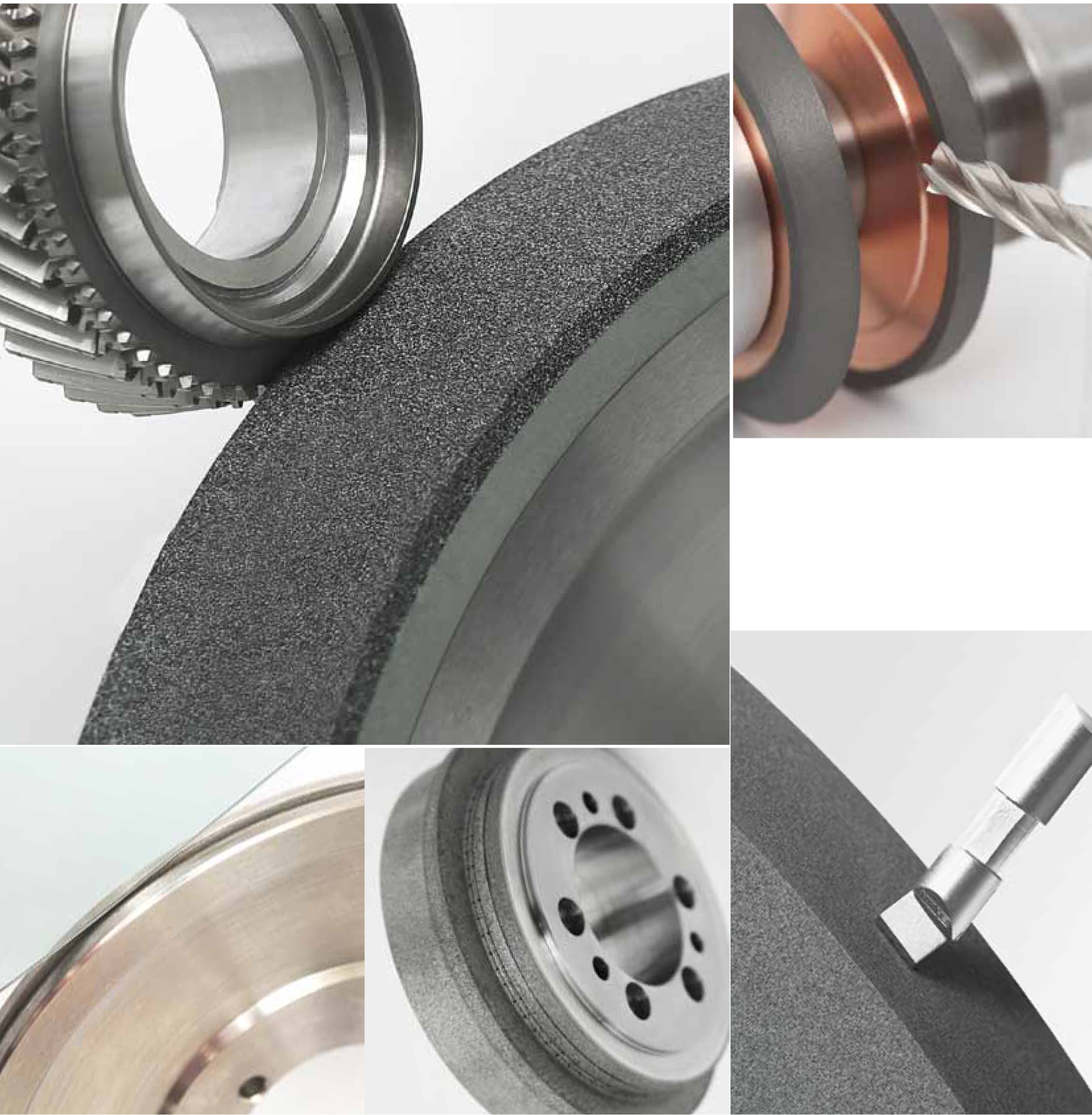
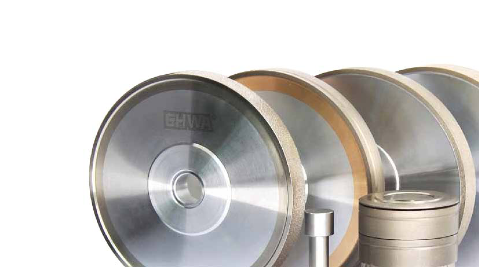
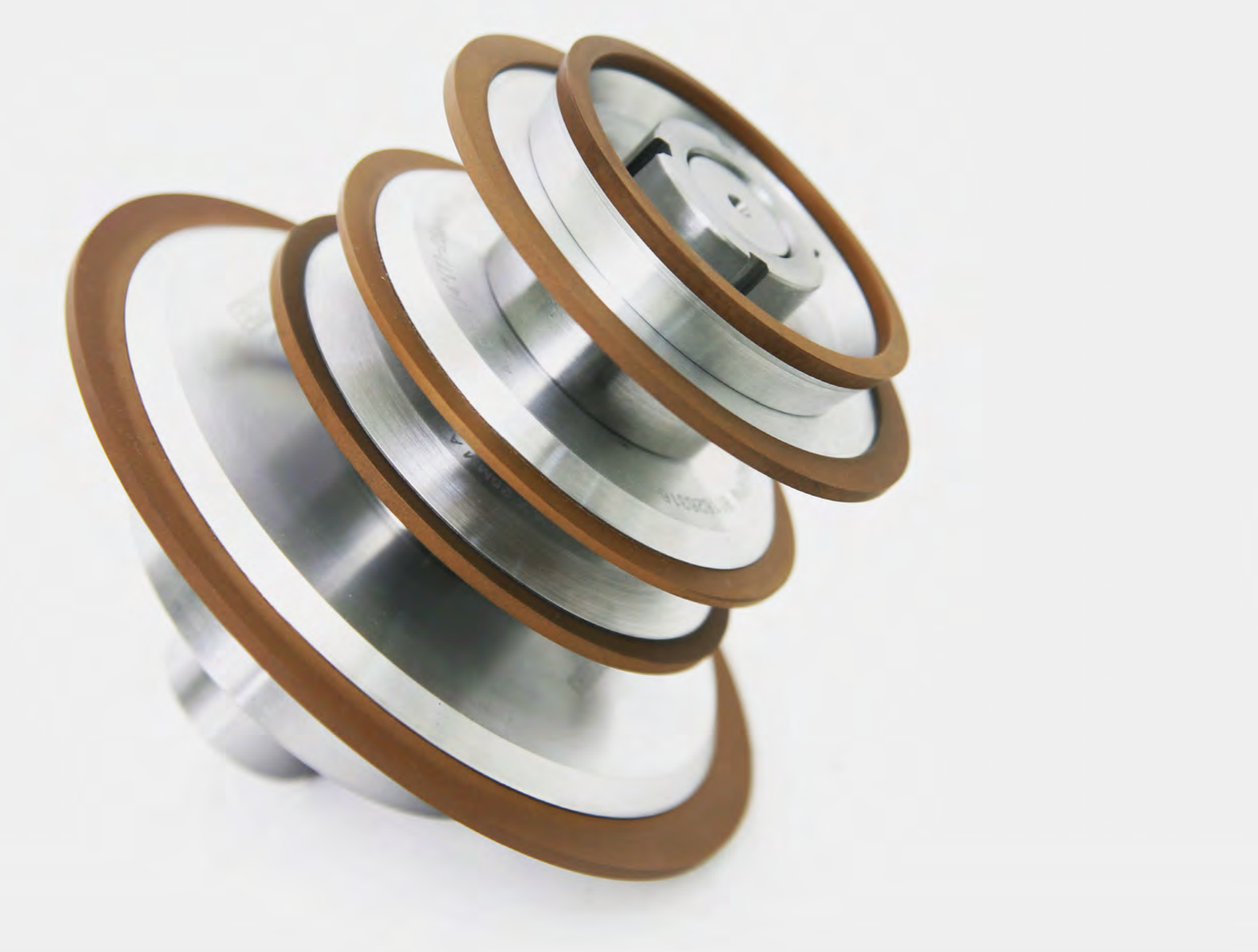
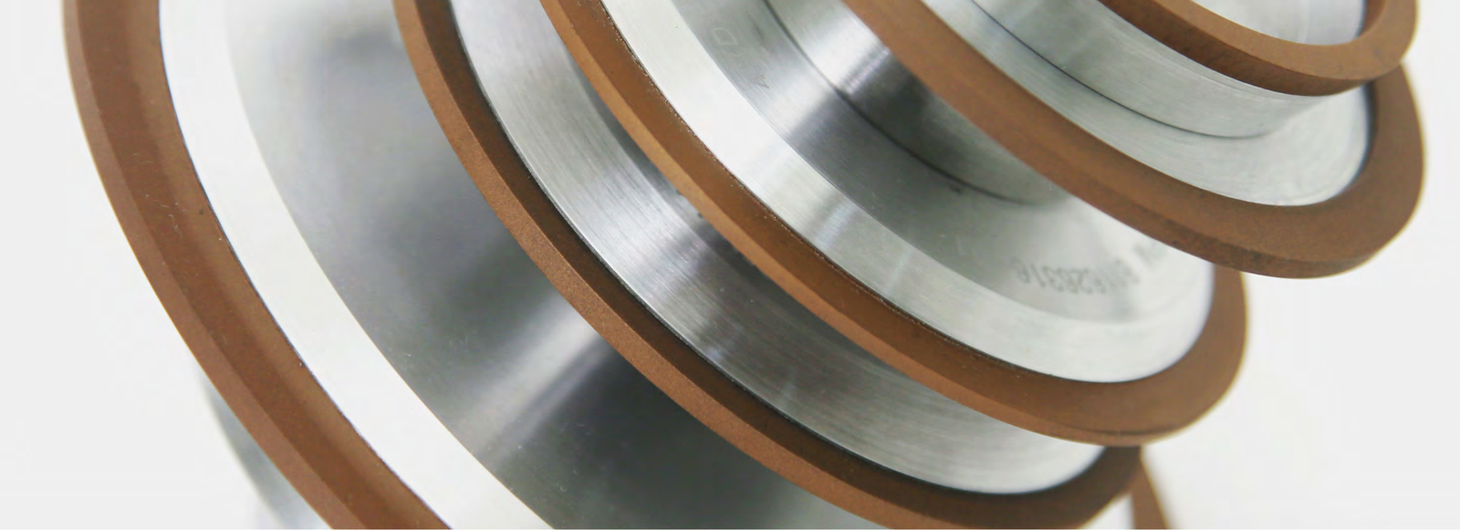
EHWA combines diamond and CBN grinding tools with application-specific dressers. The programme covers automotive components, bearings, glass, cutting tools, medical components and turbines. It also includes stationary and rotary diamond dressers, six tool/bond groups, a complete specification system and the corresponding tool shapes.
Since its founding in 1975, EHWA has developed industrial diamond tools. Quality, technical expertise and service form the basis of customer relationships. The requirements of different markets and customers inform new tools and technical information. Customer success is a measure of that collaboration.
EHWA describes international partnerships, procurement of high-quality industrial diamond and CBN from selected sources, and development cooperation with manufacturers in Europe, Japan and the USA. Joint development areas include high-precision diamond tools, rotary dressers and precision electroplated tools.
The name EHWA expresses cooperation. E refers to two parties: EHWA and people such as customers, employees, partners and society. HWA means cooperation. This gives rise to the objective of long-term customer relationships and continuing quality development.
Start with the application, then select the abrasive, bond and tool shape. The ordering and dimensional chapters connect the application examples with an unambiguous technical specification. Supplementary programmes remain identified as separate variants.
| Application area | Tool/process focus |
|---|---|
| Engine and turbocharger | Camshafts/crankshafts, injector bores, honing and dressing. |
| Gears, steering and brakes | Profile and surface machining with matching dressers. |
| Bearings | Grinding, honing and dressing for bearing components. |
| Glass | Automotive, architectural, optical and other glass applications. |
| Cutting tools | Rotating tools, inserts and saws. |
| Medical | Precision machining of medical components. |
| Turbine | Profiled grinding and dressing tasks. |
| Stationary dressers | Single-point, multi-point, form and impregnated designs. |
Development and international cooperation
The chronology below reproduces the development milestones documented in the main catalogue up to 2022. Certifications are historical milestones; their current scope is given in the relevant current certificate.
| Year | Documented milestone |
|---|---|
| 1975 | EHWA founded in Seoul, Korea. |
| 1981 | Exports to the USA began. |
| 1985 | Headquarters and production relocated to Osan. |
| 1988 | R&D centre established. |
| 1993 | ISO 9001 certification by German TÜV; plant established in Fujian, China. |
| 1995 | Sales subsidiary opened in Japan; Gold Industrial Medal received on National Trade Day. |
| 1997 | Plant established in Weihai, China. |
| 2000 | Presidential Productivity Award received. |
| 2002 | Plant established in Shanghai, China. |
| 2003 | oSa certification (Organization for the Safety of Abrasives). |
| 2004 | Sales subsidiary opened in Germany. |
| 2008 | 100 Million Dollar Export Presidential Award received. |
| 2011 | Selected as a World Class 300 company by the Korean government, first round. |
| 2012 | Plant established in Jakarta, Indonesia. |
| 2013 | New Dongtan facility opened for R&D and new business development. |
| 2015 | Subsidiaries established in India, Mexico and Italy. |
| 2016 | KOSHA 18001 certification for occupational safety and health management. |
| 2017 | Plants established in Bac Ninh and Hai Duong, Vietnam. |
| 2020 | Time-honoured Business certificate received from the Korean Ministry of SMEs and Startups. |
| 2021 | Subsidiary established in Alabama, USA. |
| 2022 | ISO 45001 certification by German TÜV. |
Engines and turbochargers
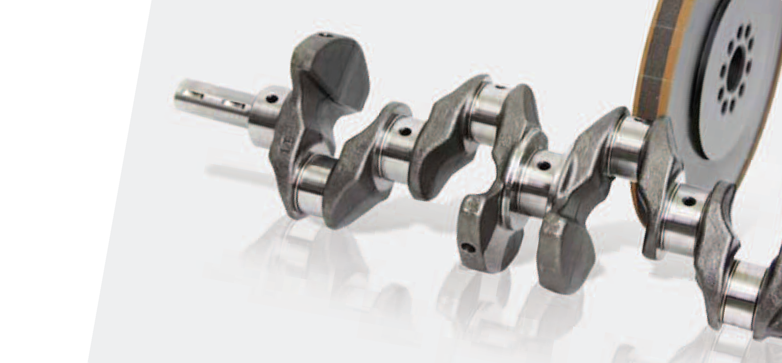
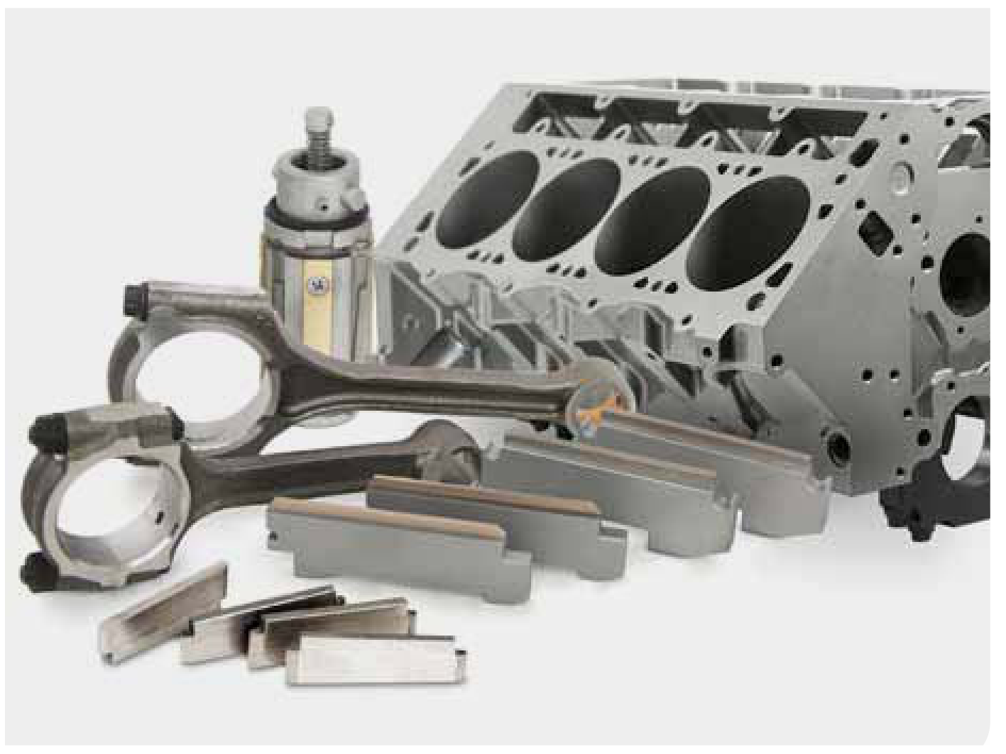
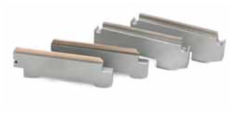
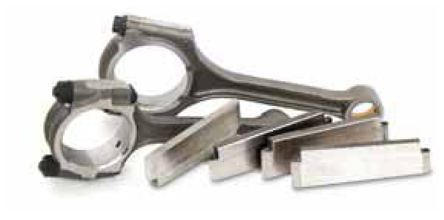
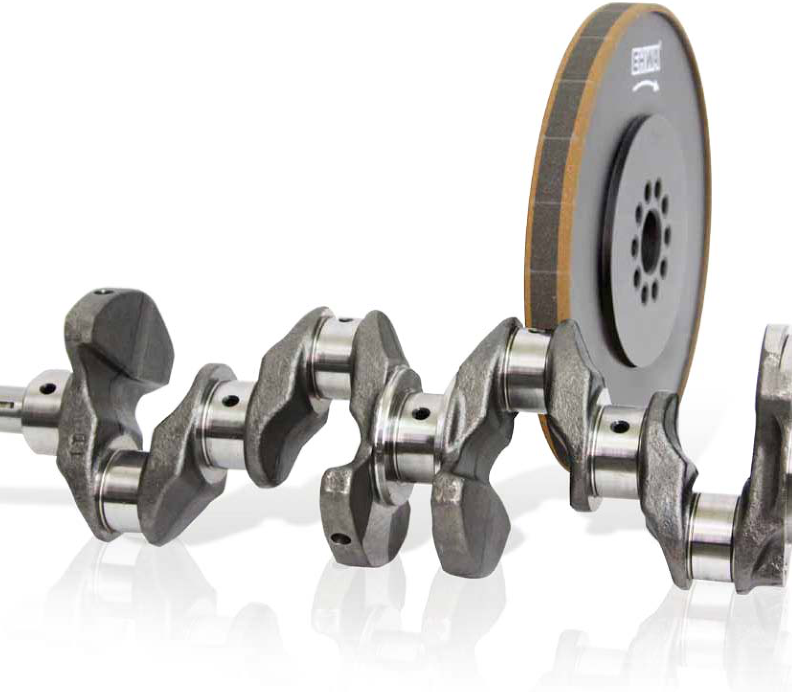
Industrial diamond tools perform important machining tasks on engine components, including cylinder heads and cylinder blocks. The programme combines vitrified-bonded CBN grinding wheels for camshafts and crankshafts with injector-bore tools, metal-bonded honing stones for cylinder blocks and connecting rods, and rotary dressers for turbochargers.
Tool selection follows the material, contour, machining stage and grinding machine. The examples below provide specific specifications and comparative results.




Camshaft grinding: removal and profile stability
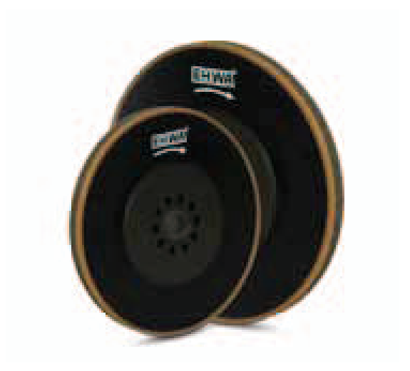
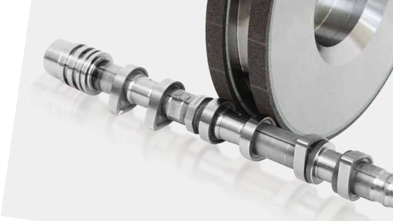
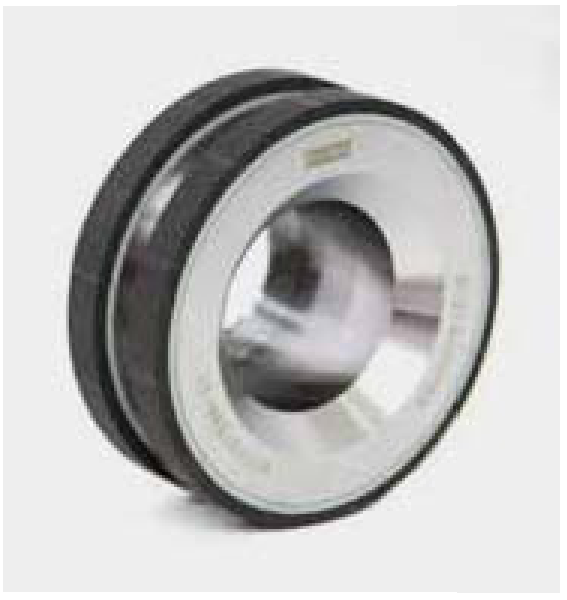
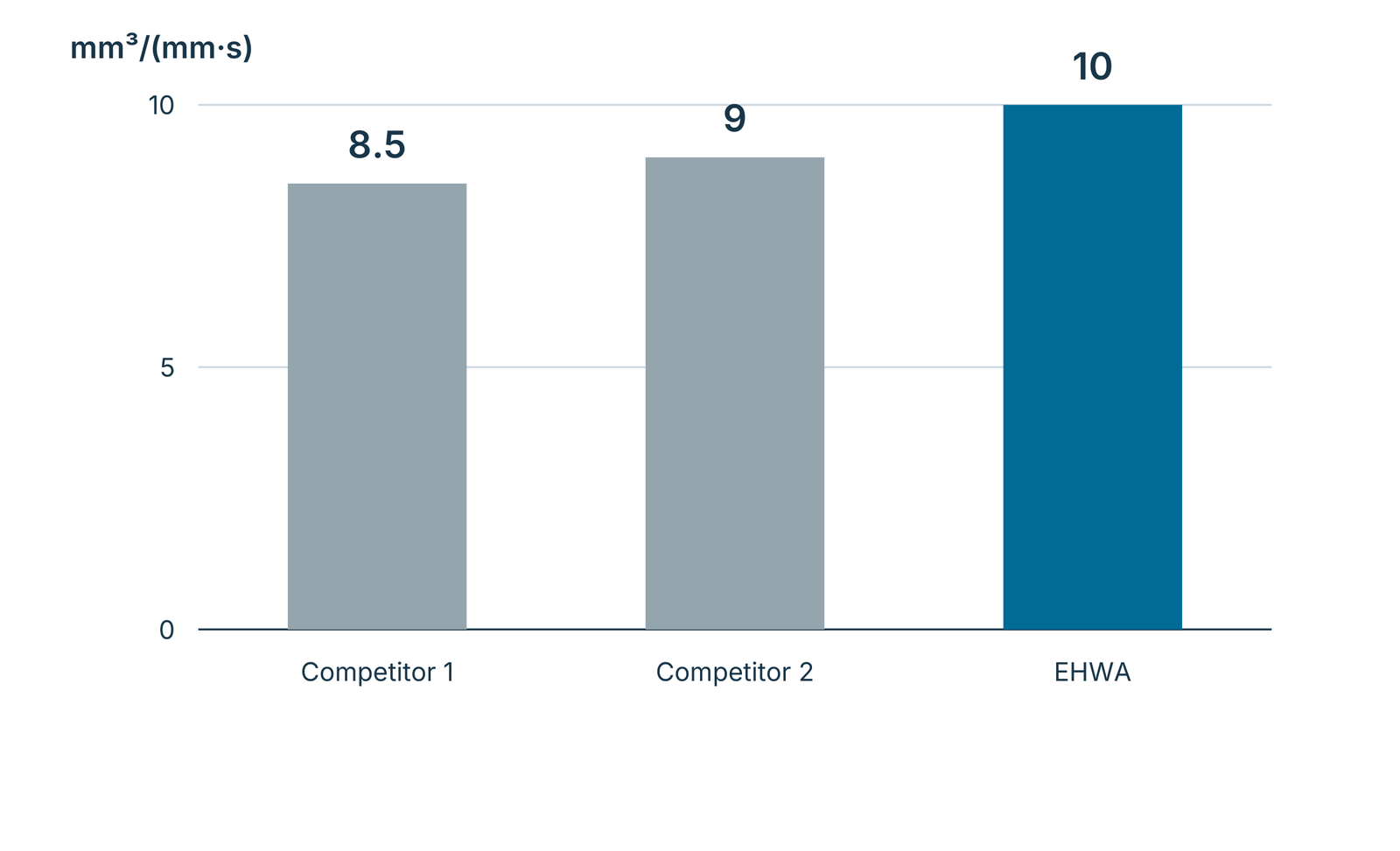
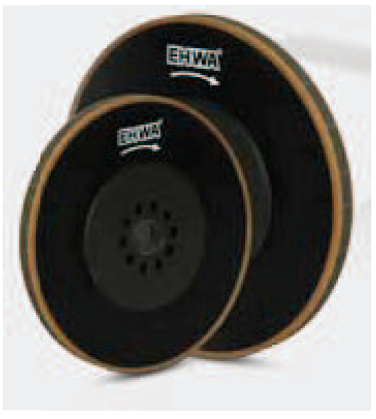
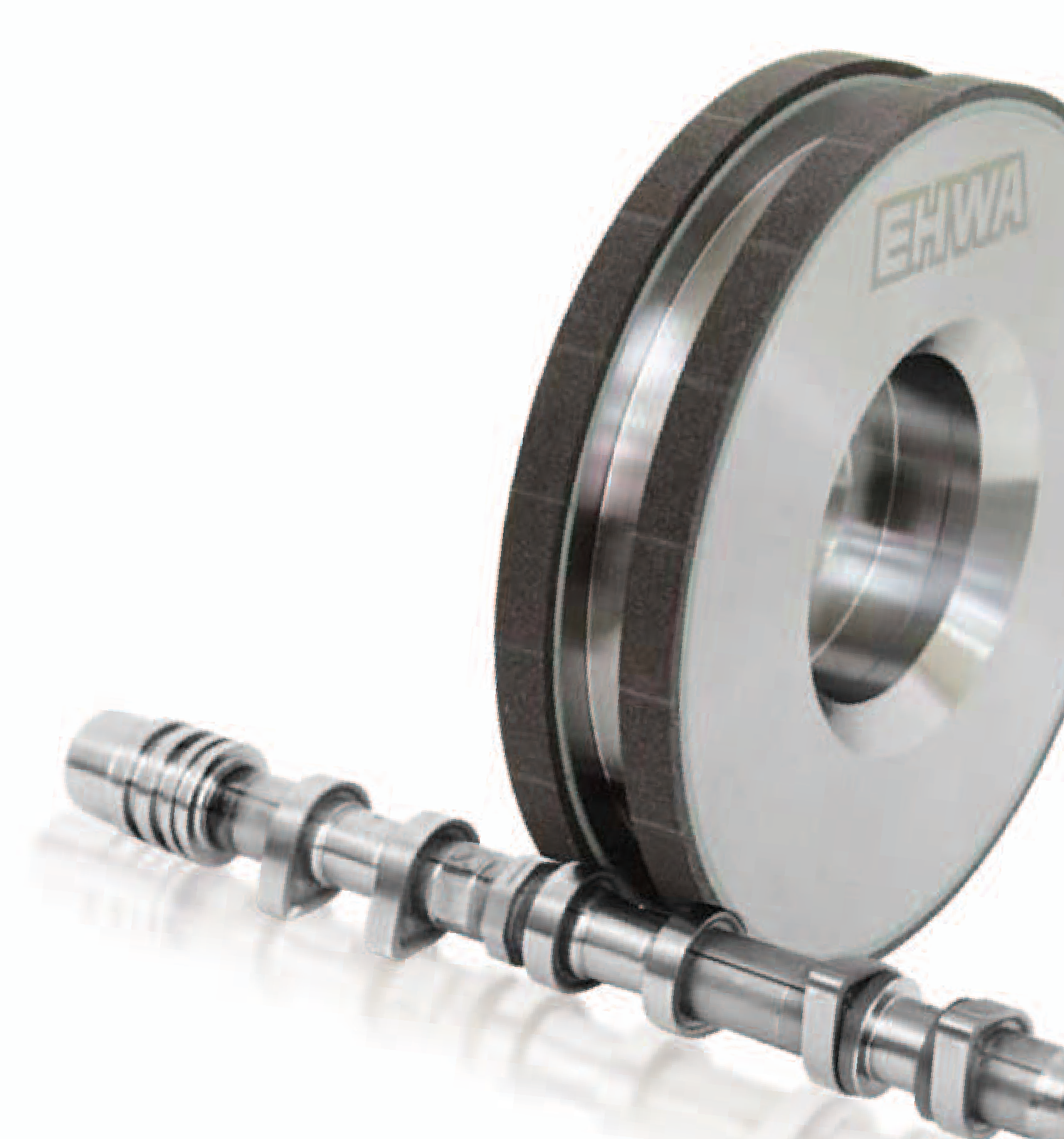
Vitrified-bonded CBN wheels combine high removal rates with low grinding forces. EHWA identifies excellent surface finish and profile stability, longer dressing intervals and extended wheel life. In the documented camshaft comparison, EHWA achieves a specific removal rate of 10 versus 8.5 and 9 for the two competing tools. Relative to Competitor 1, this corresponds to the catalogue’s increase of up to approximately 18%.
The source formula is Qw′ = π × d_w × v_f × ∂_p / b_s [mm³/(mm·s)]. Here d_w denotes workpiece diameter, v_f feed rate, ∂_p cam-lobe width and b_s grinding-wheel width. The formula and the parameters below belong to this comparison case.
| Comparison condition | Value |
|---|---|
| Work material | Chrome-molybdenum steel, sintered |
| EHWA | B126L200VEW |
| Wheel speed v_s | 120 m/s |
| Feed rate v_f | 0.08 mm/s |
| Stock removal | 0.8 mm |
| Cam-lobe diameter d_w | 30–50 mm |
| Wheel diameter d_s | 450 mm |
| Tool | Qw′ [mm³/(mm·s)] |
|---|---|
| Competitor 1 | 8.5 |
| Competitor 2 | 9 |
| EHWA | 10 |
Crankshaft grinding: longer wheel life
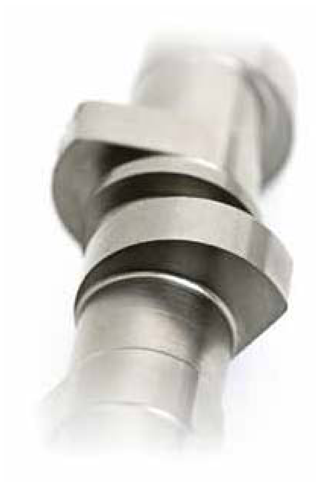
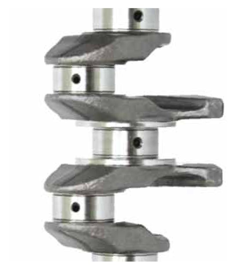
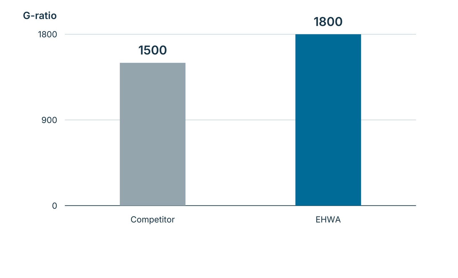
EHWA identifies longer dressing intervals and tool life, consistent surface finish, high profile stability and reduced thermal and mechanical damage to the workpiece. In the illustrated comparison, the G-ratio rises from 1500 to 1800; the catalogue describes this as a 20% increase in wheel life.
The G-ratio is the removed workpiece volume divided by the CBN grinding-wheel wear volume. The comparison values relate to the conditions below.
| Comparison condition | Value |
|---|---|
| Work material | FCD, cast material |
| EHWA | B151L200VEWN |
| Wheel speed v_s | 80 m/s |
| Feed rate v_f | 0.05 mm/s |
| Stock removal | 1.2 mm |
| Workpiece diameter d_w | 60 mm |
| Wheel diameter d_s | 650 mm |
| Tool | G-ratio |
|---|---|
| Competitor | 1500 |
| EHWA | 1800 |
Injector bores and seat surfaces
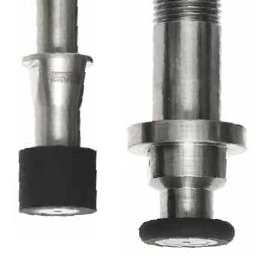
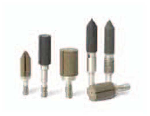
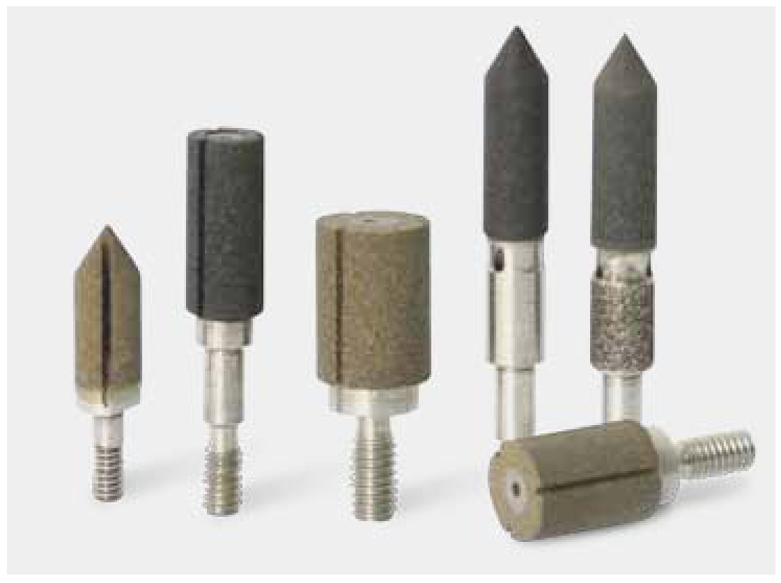
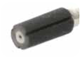
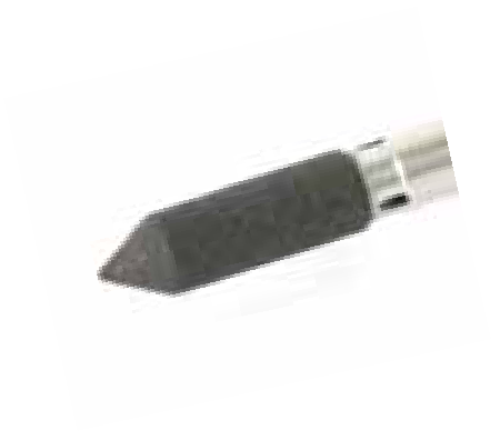
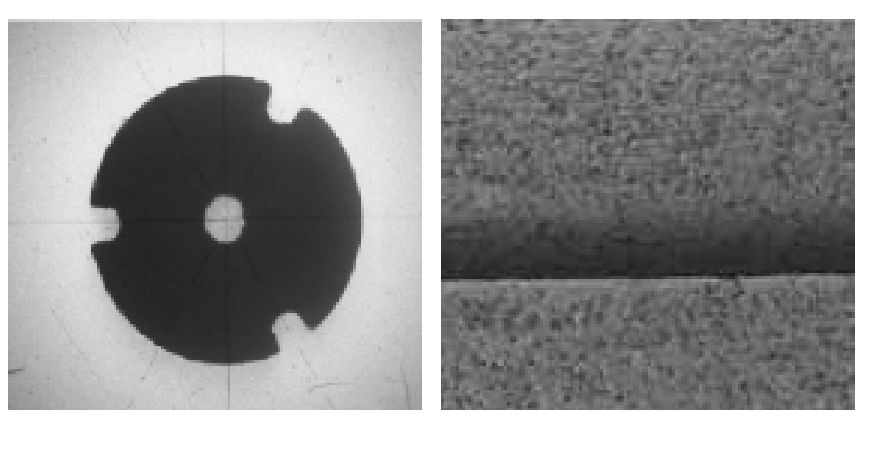
The tools are designed for fuel-injector bore and seat machining. EHWA identifies free-cutting abrasive, longer dressing intervals and more efficient tool utilisation. Consistent grinding performance and precise wheel forms, including coolant holes and slots, support the machining task.
The standard specifications below apply to the bore and seat tools illustrated in the main programme.
| Feature | Bore / seat |
|---|---|
| Coolant hole | H 0.5–1.0 mm |
| Wheel size | D 1.5–20 mm |
| CBN grit size | 29–76 µm |
| Slot | 0.4–1.5 mm |
Metal-bonded honing stones for cylinder blocks and connecting rods
Metal-bonded honing stones combine longer tool life with the objective of lower machining costs. For cylinder blocks, the programme distinguishes roughing, semi-finishing and finishing. Connecting rods have a separate grit/bond selection.
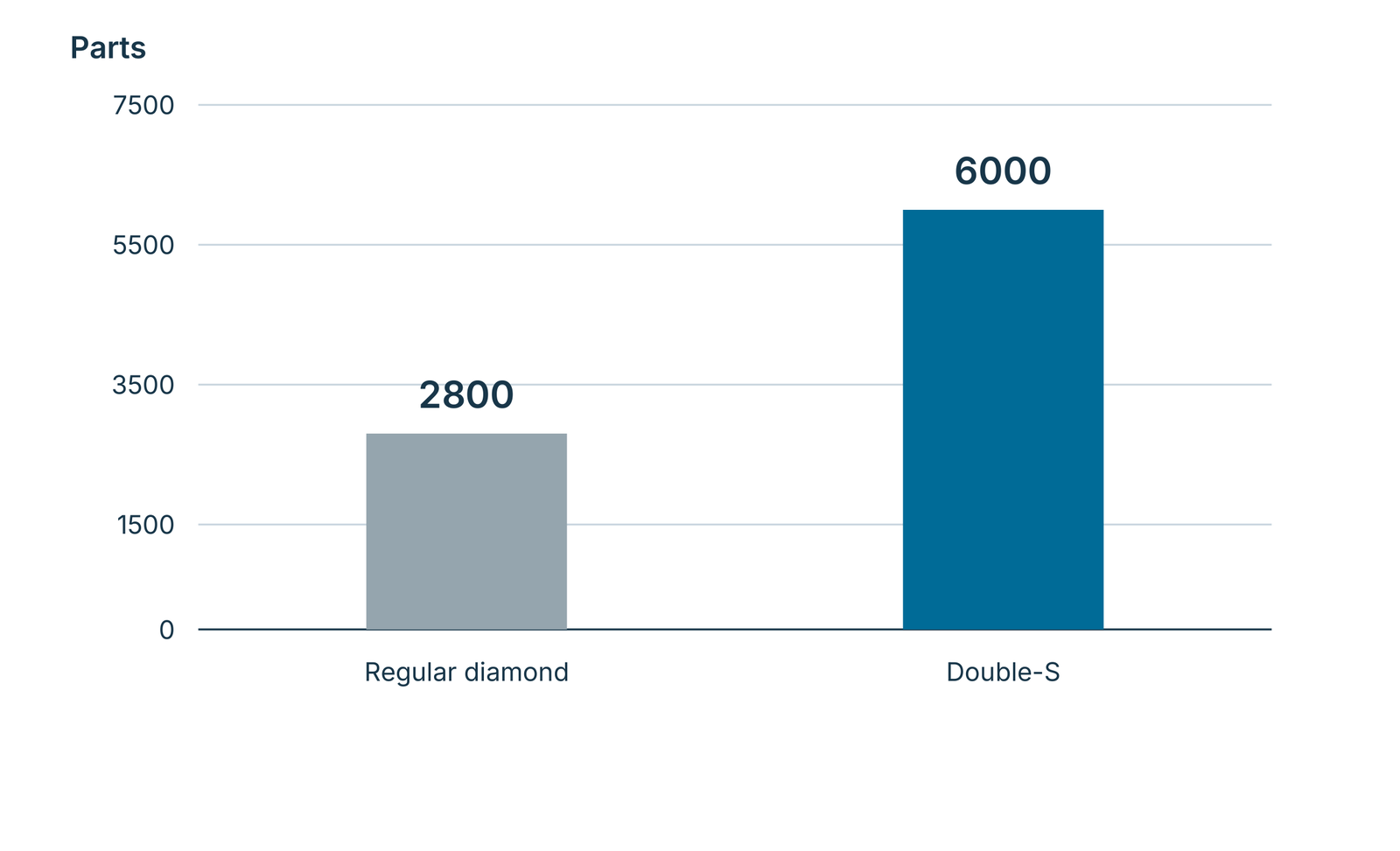
Double-S uses a specially coated diamond. EHWA identifies excellent roundness and surface finish, and describes doubled tool life. The illustrated comparison shows 2800 machined parts for regular diamond versus 6000 parts for Double-S. These tool-life figures are results from the application example shown.
| Cylinder block: stage | Grit designations | Bond series |
|---|---|---|
| Rough | D251–D91 | MB, MS, MJ |
| Semi-finish | D76–D30 | MB, MS, MJ |
| Finish | D25–D8 | MJ, MH |
| Connecting rod: grit designations | Bond series |
|---|---|
| D151–D25 | MJ, MH, MS |
| Diamond | Tool life [parts] |
|---|---|
| Regular diamond | 2800 |
| Double-S | 6000 |
Rotary dressers for engine valves
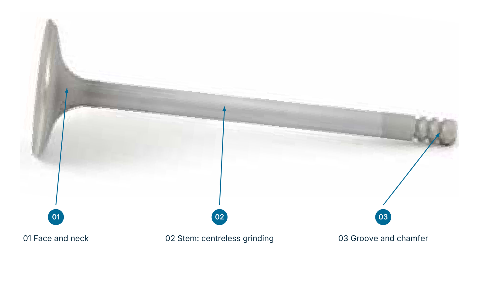
An engine valve has a head, sealing face and stem. It controls gas exchange: the inlet valve admits the air or mixture required for combustion, while the exhaust valve releases the combustion gases.
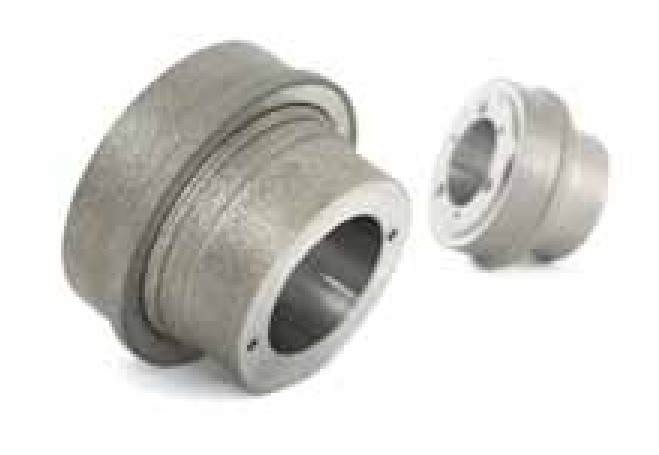
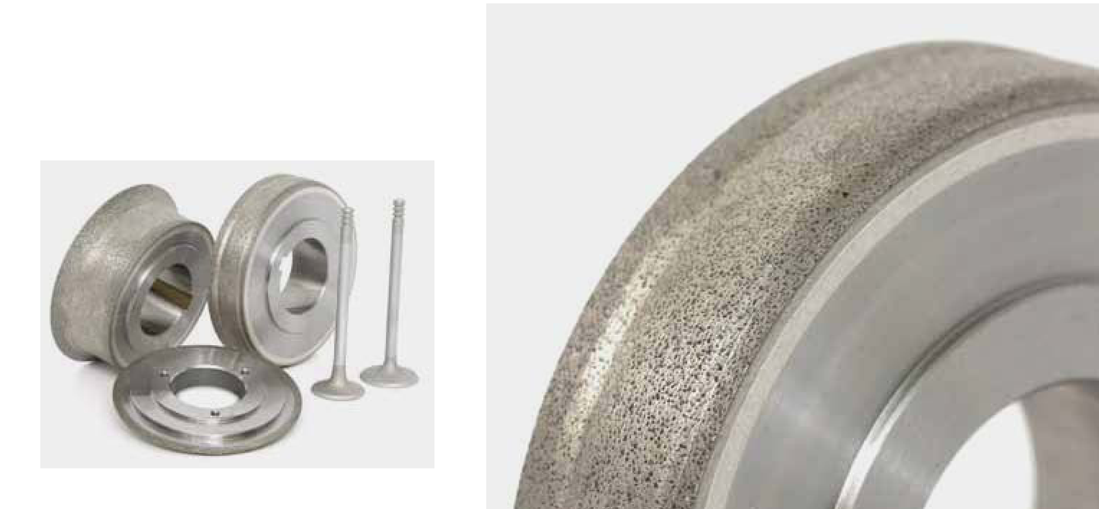
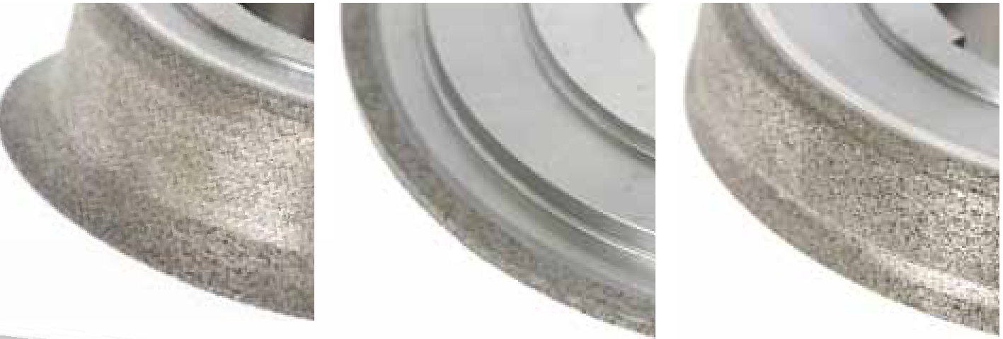
EHWA tailors the dressers to the customer’s task and identifies high-precision dressing with long tool life. Designs can be supplied as a single tool or an assembly. The three illustrated assignments cover face and neck, centreless stem grinding, and groove and chamfer.
| Mark | Machining area |
|---|---|
| 01 | Face and neck |
| 02 | Stem: centreless grinding |
| 03 | Groove and chamfer |
Rotary dressers for turbochargers
A turbocharger uses a turbine to supply additional air to the combustion chamber. This can support the power output and efficiency of an internal-combustion engine.
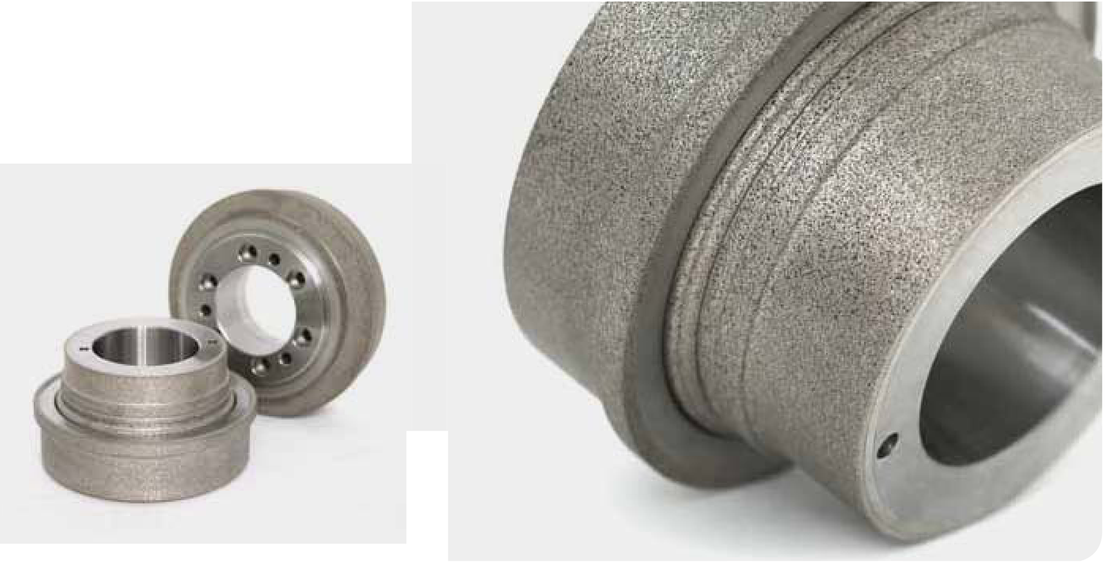
EHWA identifies customer-specific design, high-precision dressing and longer tool life. CVD reinforcement at key wear areas increases service life. The two diagrams show the arrangements “Synchronous” and “Shaft grinding”.

Gears, steering and brakes
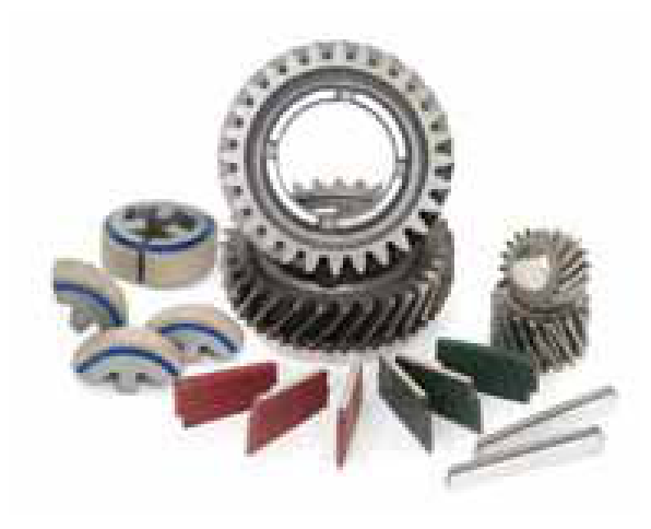
The programme combines gear-grinding dressers, honing stones for transmission components, and CBN tools for angular and internal grinding. CV-joint applications use vitrified CBN tools and matching rotary dressers. Brake applications include CBN segments for discs, and BSL and electroplated tools for pads.

Dressers for gear grinding
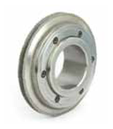
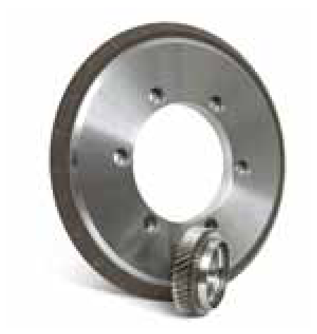
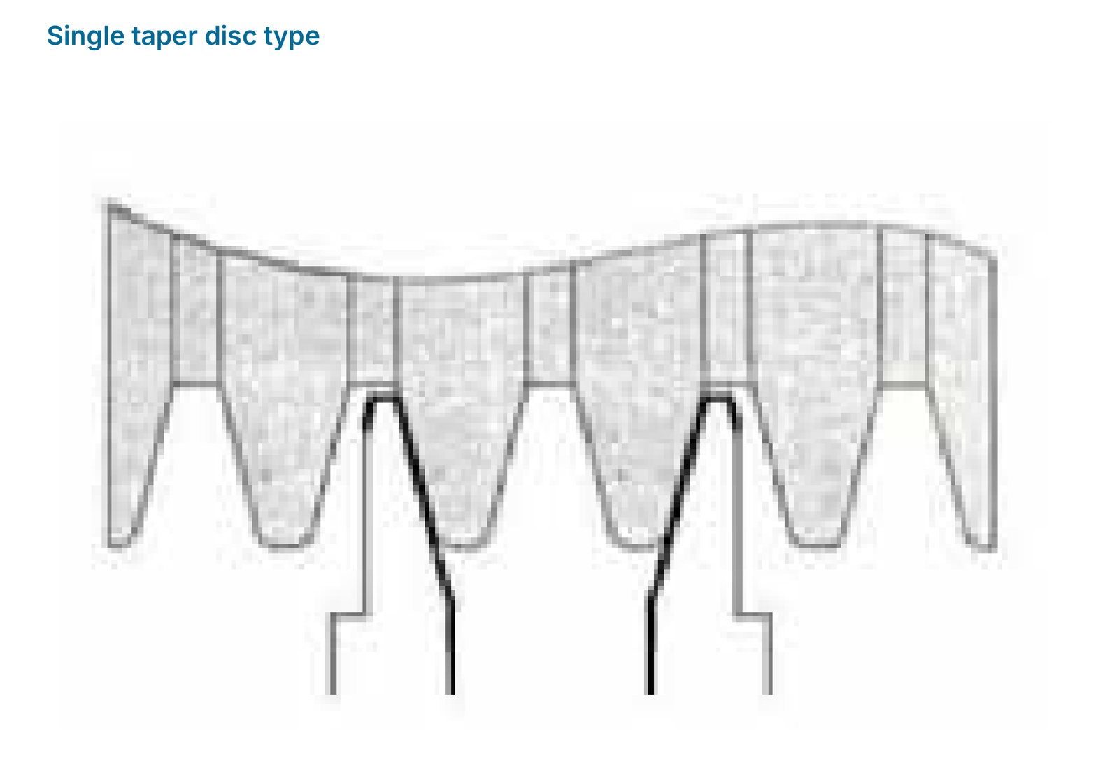
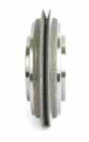
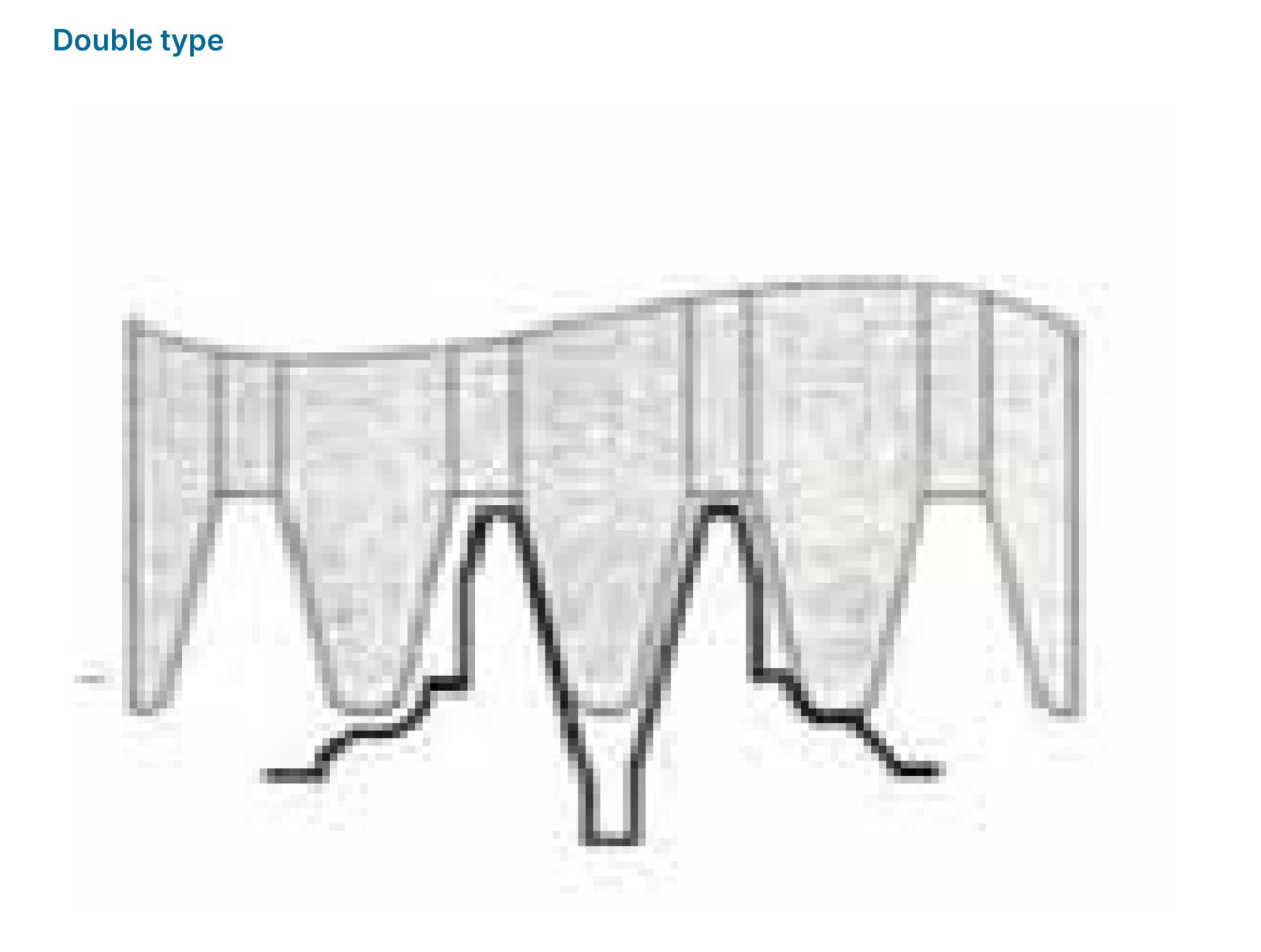
Controlled raw materials and precisely polished dressing contours support the required profile accuracy. The dresser profiles the grinding worm that subsequently grinds the gear.
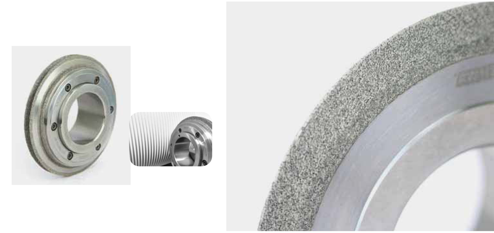
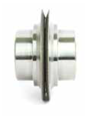
The main catalogue shows four designs: Single taper disc type, Single cone type, Single and root type, and Double type. Each has its own tool view and profile-contact view. The illustrated contours belong to this programme edition.
| Design | Profile principle |
|---|---|
| Single taper disc type | Two separate profile sections. |
| Single cone type | A single main profile. |
| Single and root type | Main profile and lower root section. |
| Double type | Two profile tips on a common body. |
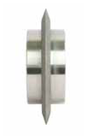
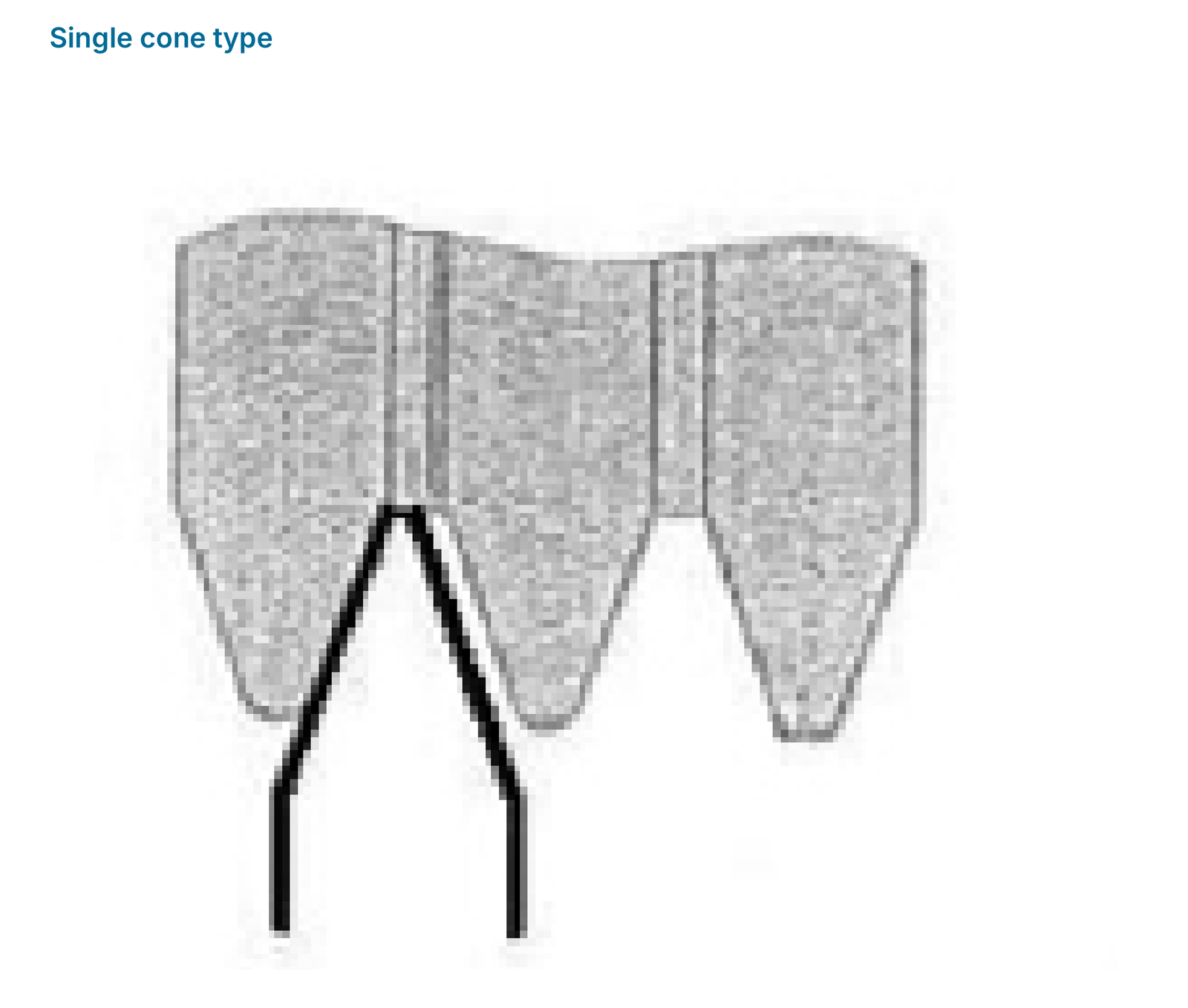
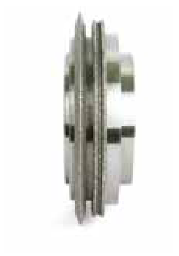
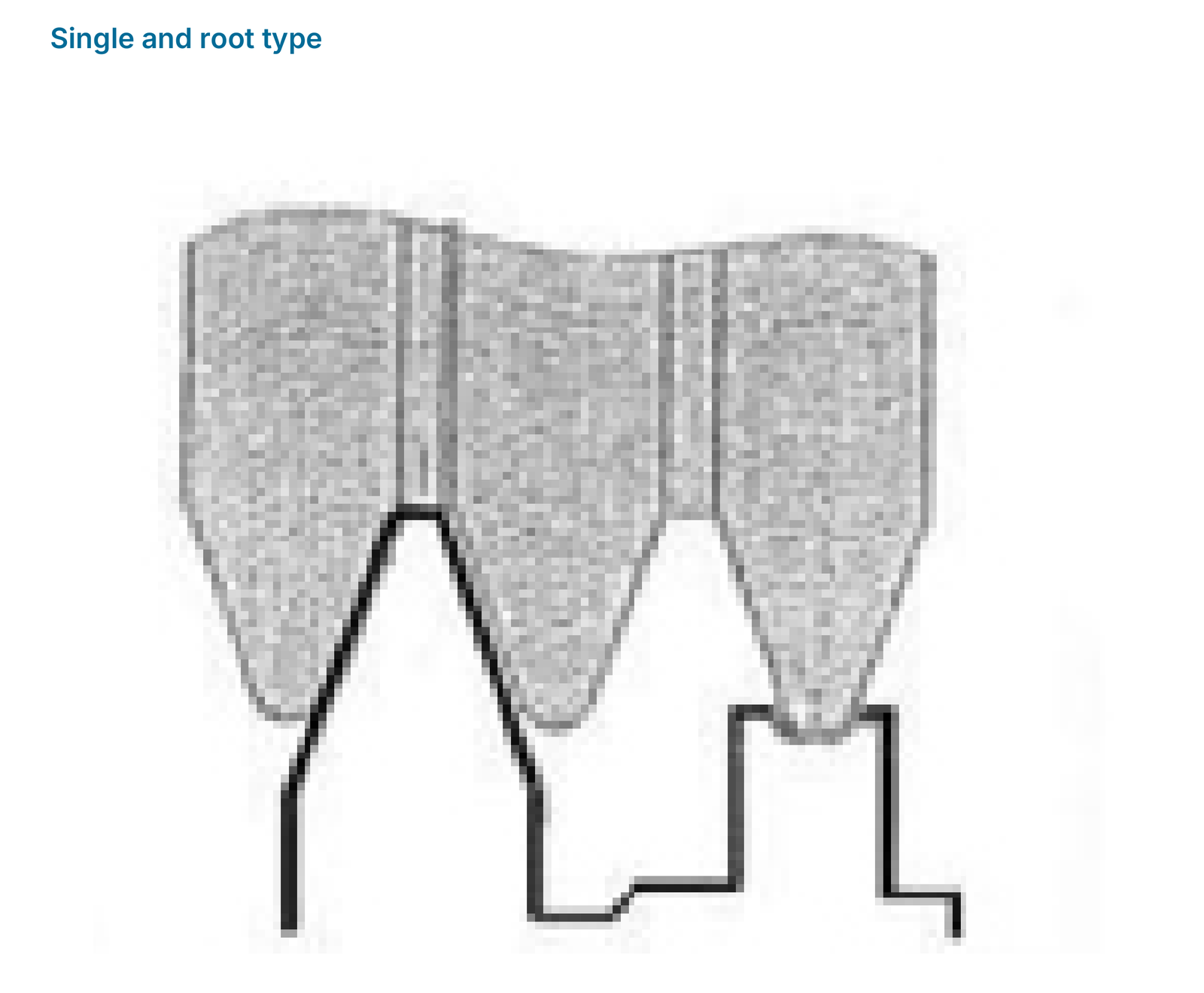
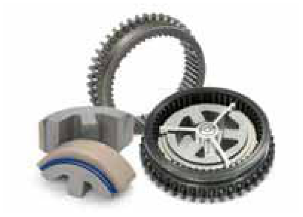
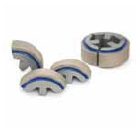
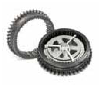
Honing stones for transmission components and synchro sleeves
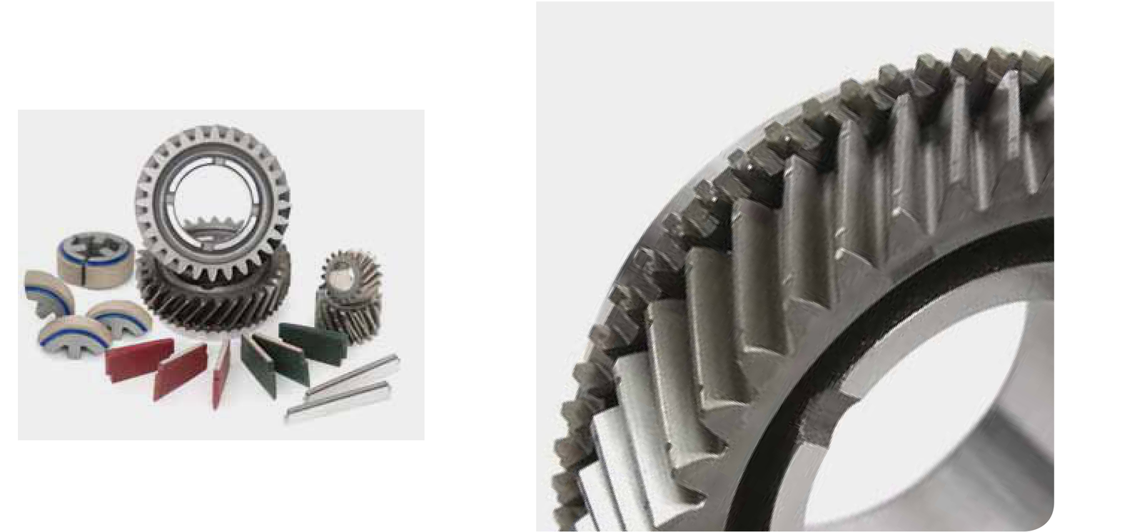
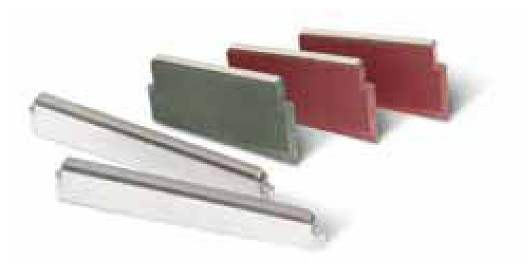
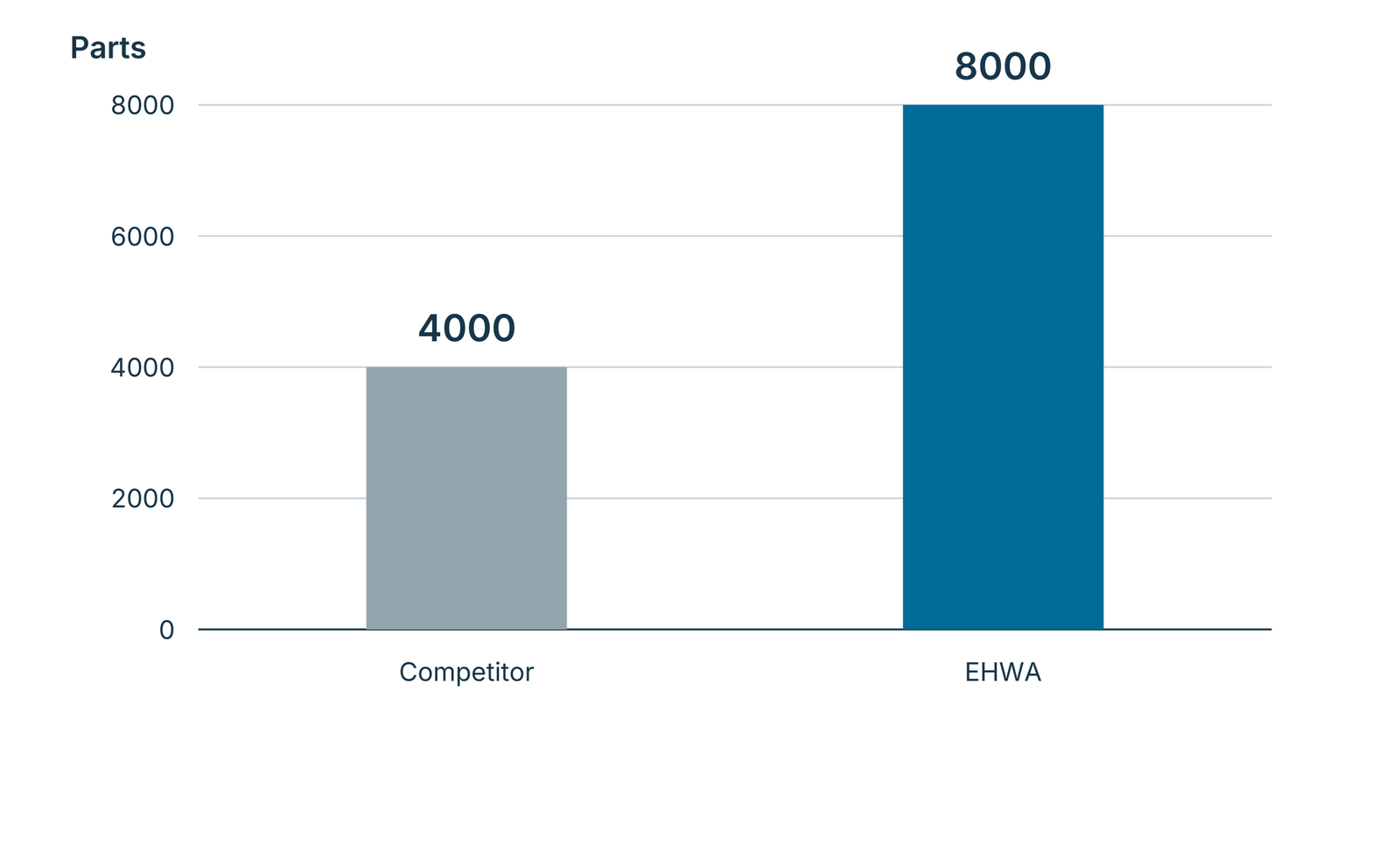
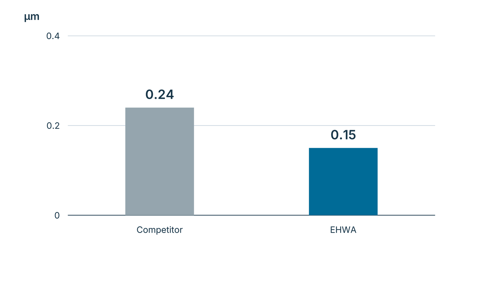
For pinions, speed gears and DCT components, EHWA identifies longer tool life, lower costs and machining load, and excellent roundness. The illustrated comparison shows 4000 parts for the competing tool and 8000 parts for EHWA. Roundness values are 0.24 µm and 0.15 µm respectively.
For synchro sleeve gears, effective internal-bore honing is the focus. EHWA identifies longer tool life and better precision than the competing product. The two application types have different grit and bond ranges.
| Application | Grit designations | Bond series |
|---|---|---|
| Pinion, speed gear, DCT component | D181–D15 | MB, MH, MS, MJ |
| Synchro sleeve: internal bore | D76–D20 | MB, MS |
| Comparison | Tool life [parts] | Roundness [µm] |
|---|---|---|
| Competing tool | 4000 | 0.24 |
| EHWA | 8000 | 0.15 |
Angular grinding of transmission components
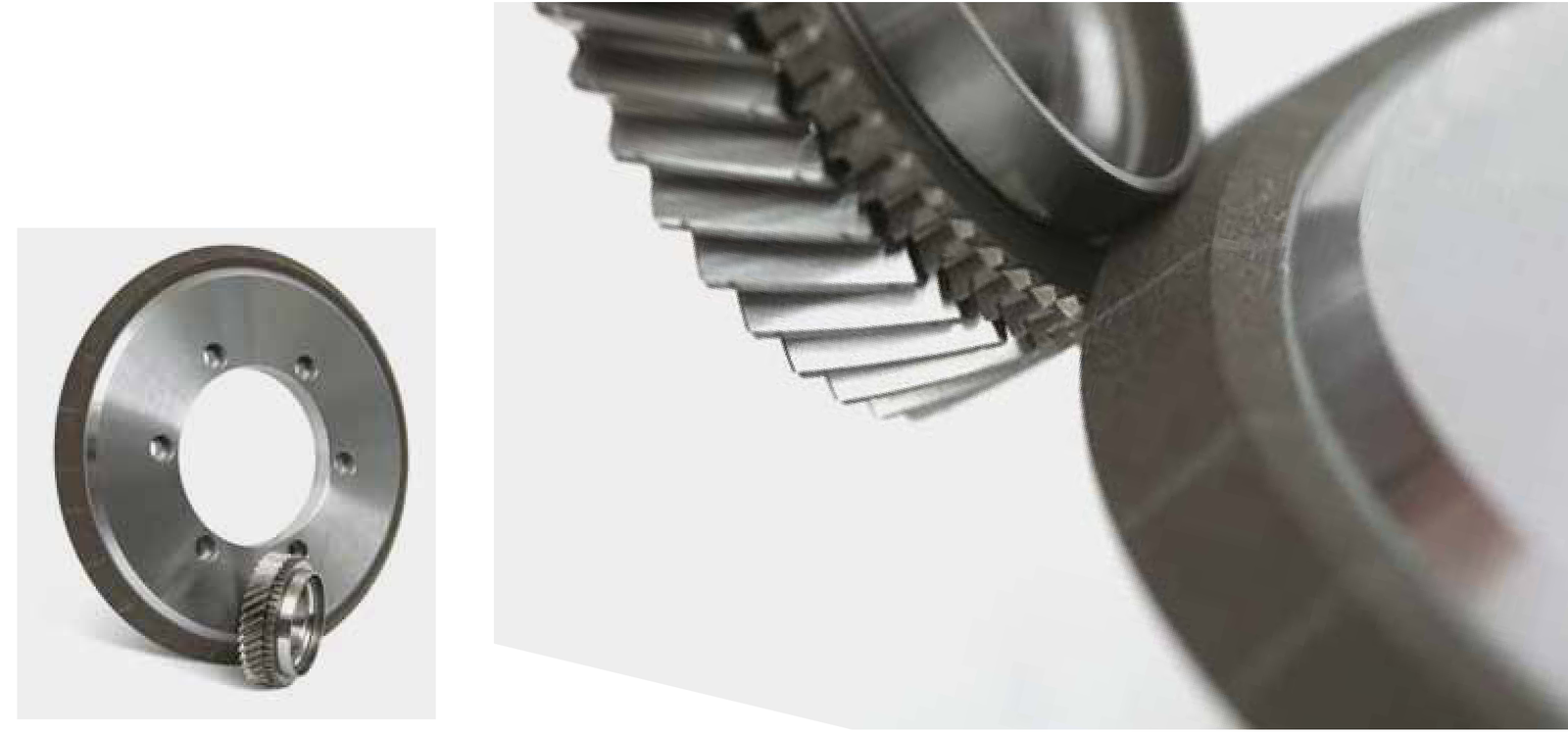
Vitrified-bonded CBN tools provide high grinding performance for transmission components. Their free-cutting design supports high removal rates; longer dressing intervals contribute to economical production with high capacity. EHWA also identifies shorter cycles and reduced mechanical and thermal damage to the machined surface.
The following conditions belong to the illustrated angular-grinding application.
| Feature | Value |
|---|---|
| Wheel speed | 25–80 m/s |
| Diametral stock removal | 0.1–0.35 mm D |
| Dressing amount | 5–30 µm |
| Dresser | Diamond rotary dresser |
| Spindle-axis angle | 15° / 30° / 45° |
| Body material | Steel, aluminium alloy |

Internal grinding with CBN
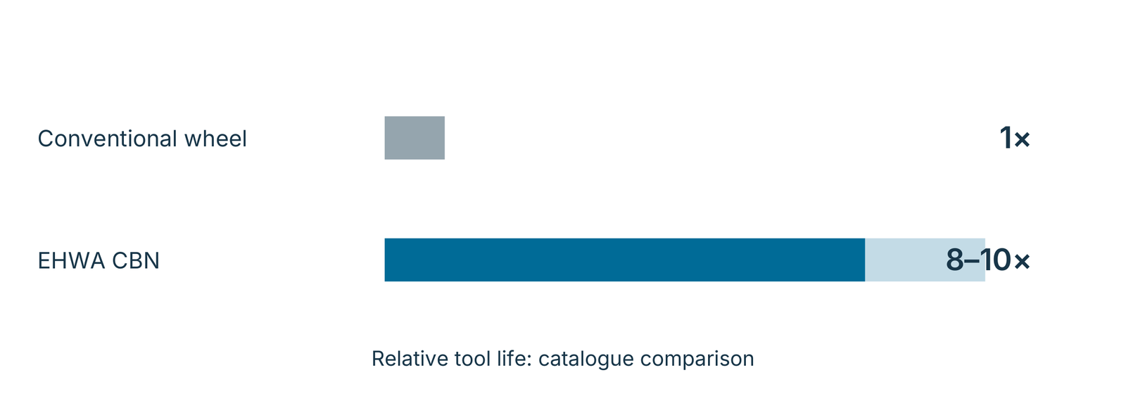
EHWA identifies excellent surface quality, longer wheel life and lower costs, faster production-line setup and high stock removal. The catalogue comparison indicates eight to ten times the wheel life of a conventional wheel for EHWA CBN. Achievable life is matched to the work material, grinding machine and operating conditions.

CV joints: cage windows and outer race
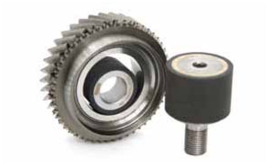
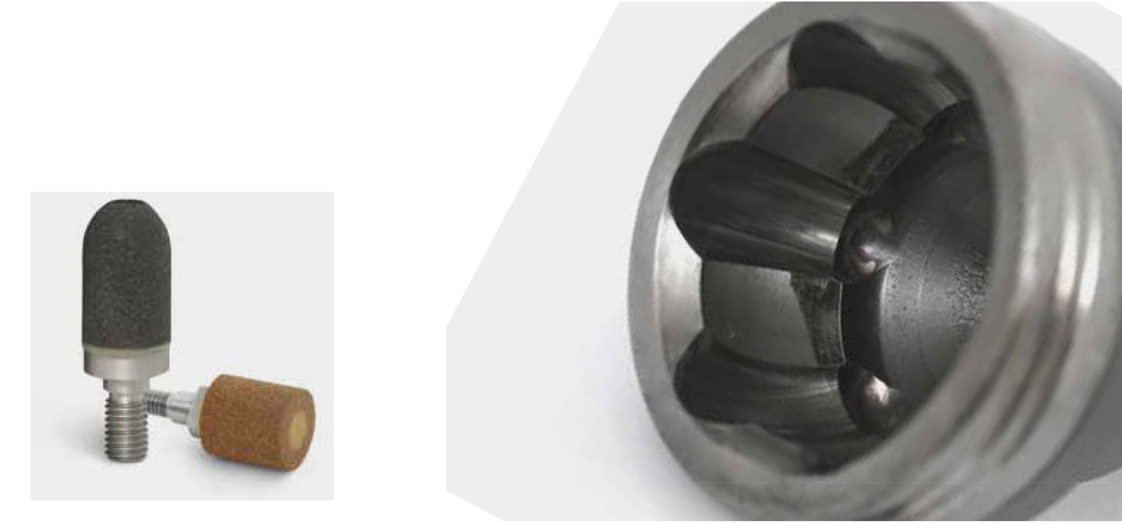
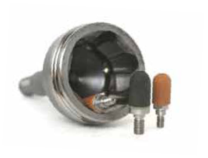
The specialised CBN tools support high removal and production capacity. EHWA identifies excellent surface quality with low heat generation and tight tolerances. Longer dressing intervals and reduced wheel wear improve process consistency and support lower costs.
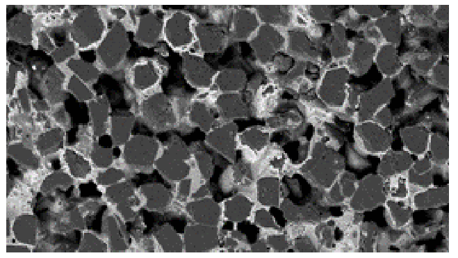
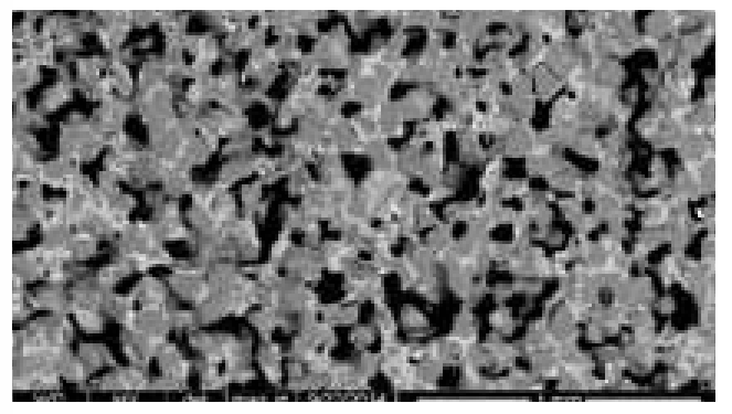
Cage windows and outer races have separate standard specifications. The corresponding CBN and pore-structure images illustrate the different tool designs.
| Machining area | Standard specification |
|---|---|
| Cage windows | B126M180VBTM |
| Outer race | B181M160VBTM |

Rotary dressers for CV joints
CV joints transfer torque supplied by the engine through the transmission to the wheels while maintaining constant-velocity rotation between the connected shafts. Precisely machined contours support this function.
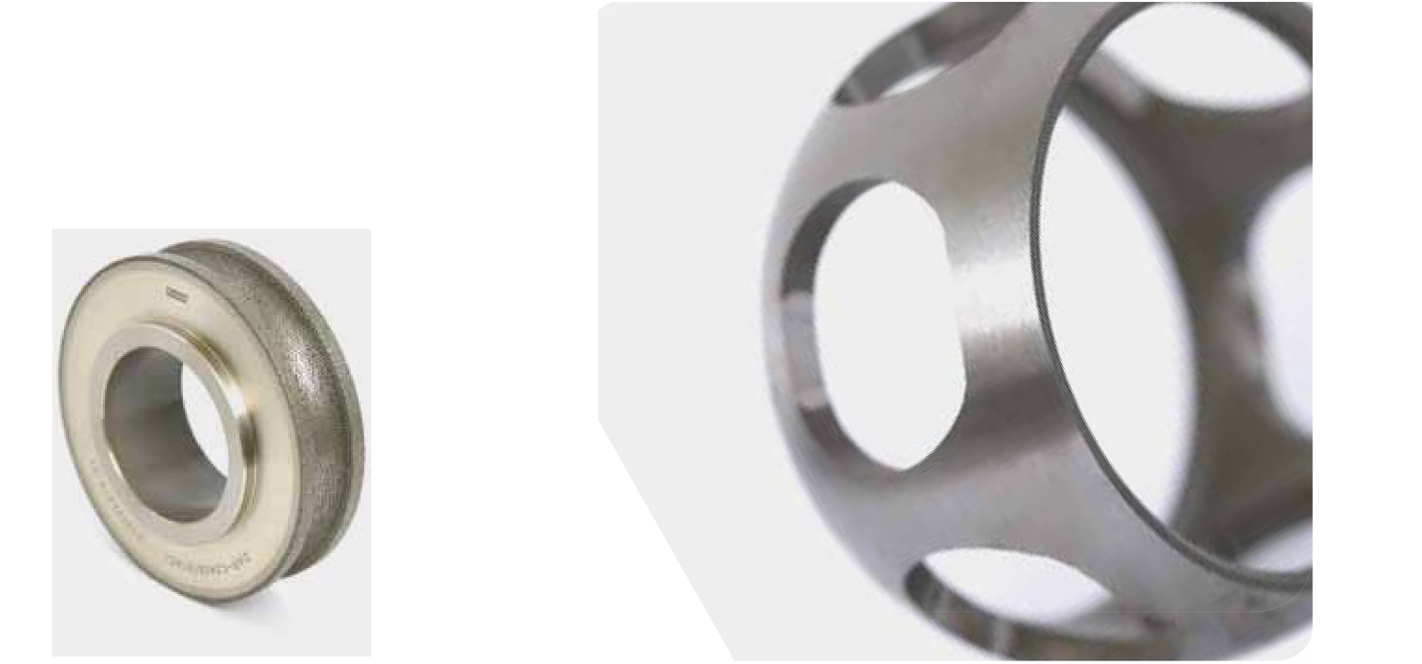
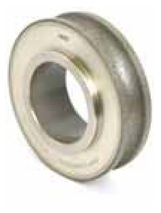
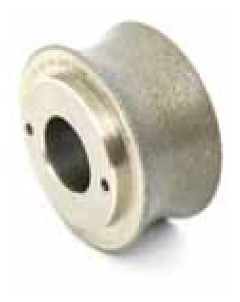
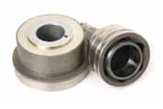
EHWA identifies customer-specific design, high dimensional precision and excellent machining performance through high diamond exposure. The three dresser groups are assigned to the inner race, cage and outer diameter of the outer race.
| Assignment | Tool group |
|---|---|
| Inner race | Rotary diamond dresser |
| Cage | Rotary diamond dresser |
| Outer-race outside diameter | Rotary diamond dressers |
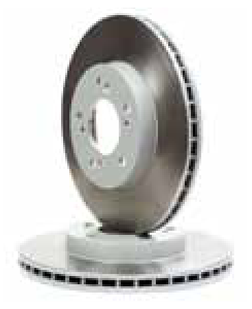
CBN segments for brake discs
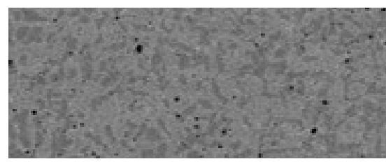
CBN segments support longer tool life and economical machining. EHWA identifies shorter cycles through high grinding speeds. The two workpiece groups have separate bond series and corresponding scanning electron micrographs.
The D181–D54 grit designations follow the table in the main programme; the abrasive is confirmed when the order specification is agreed.
| Workpiece group | Grit designations | Bond series |
|---|---|---|
| 4WD (FC) | D181–D54 | MH |
| 2WD (SUS) | D181–D54 | MP |


BSL and electroplated tools for brake pads
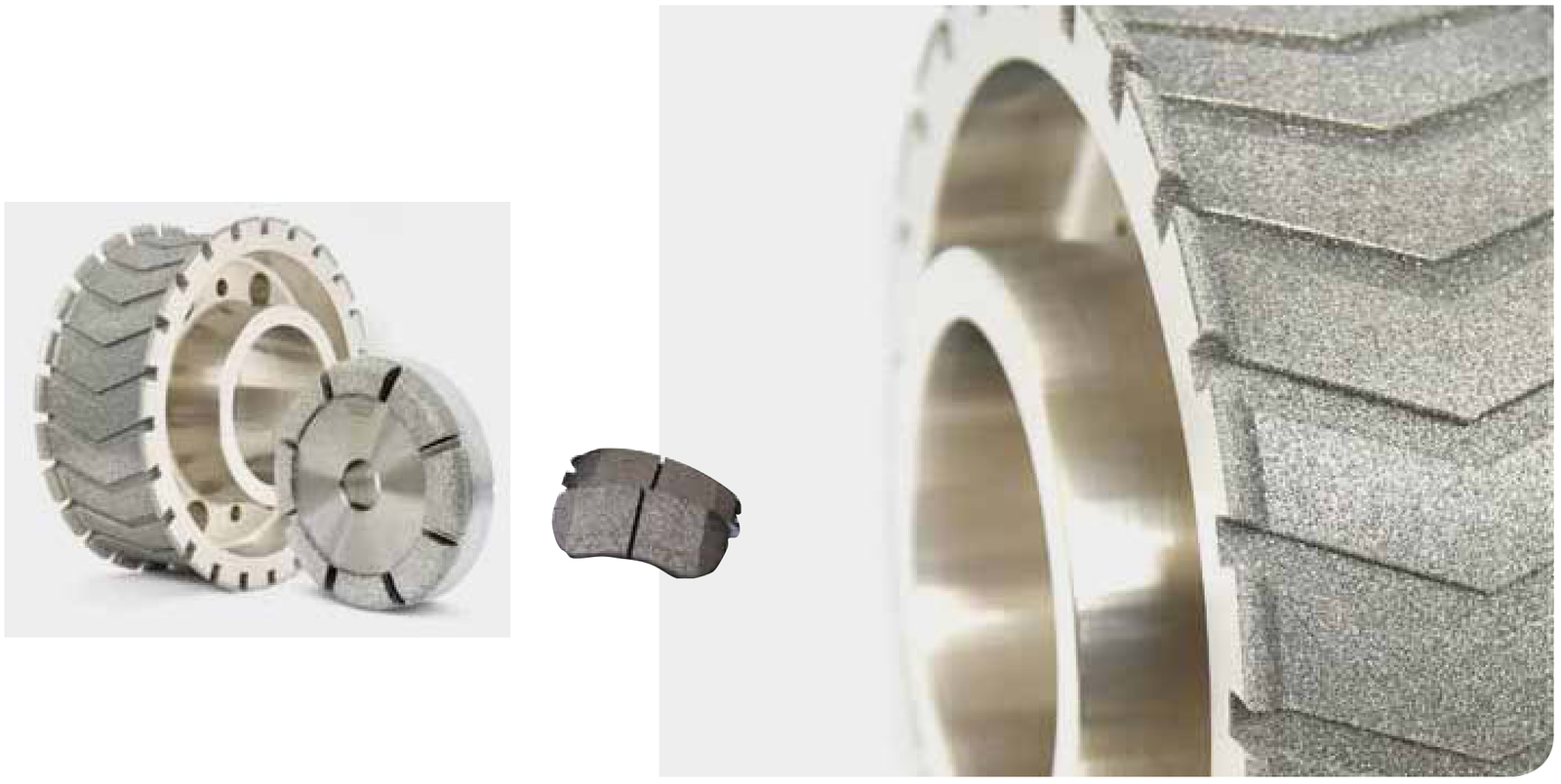
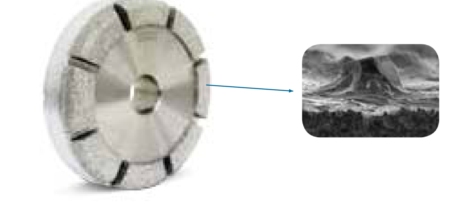
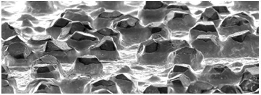
BSL tools combine high diamond exposure with free-cutting machining and effective chip flow. EHWA identifies longer tool life than electroplated tools and the resulting cost benefits.
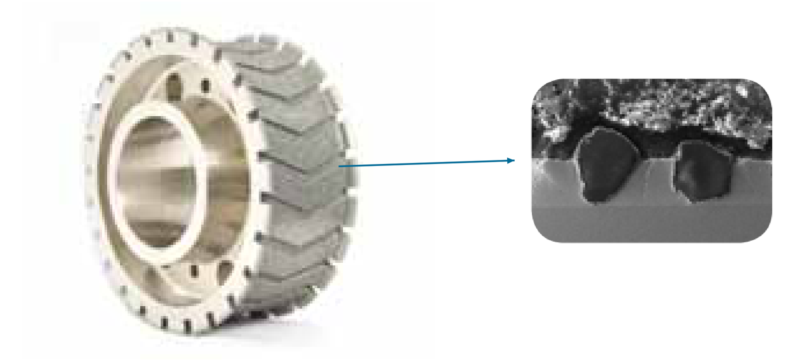
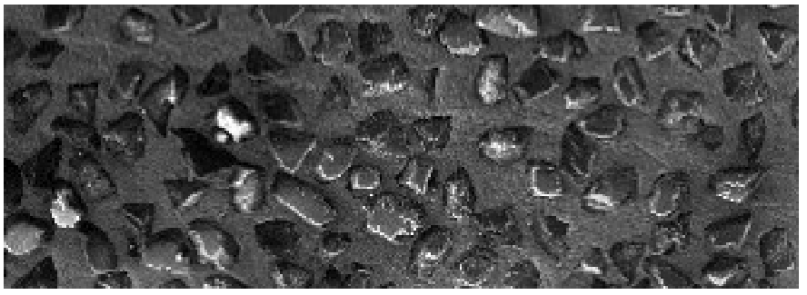
Electroplated designs are suitable for coordinated chamfer, slot and face grinding. Different and complex tool shapes support the task. The listed materials include composites, ceramics and rubber. EHWA highlights high grinding performance and the possibility of repeated refurbishment.
The tool/detail pairs and the structure images present the two abrasive-layer designs separately.
Bearings: grinding, superfinishing and dressing
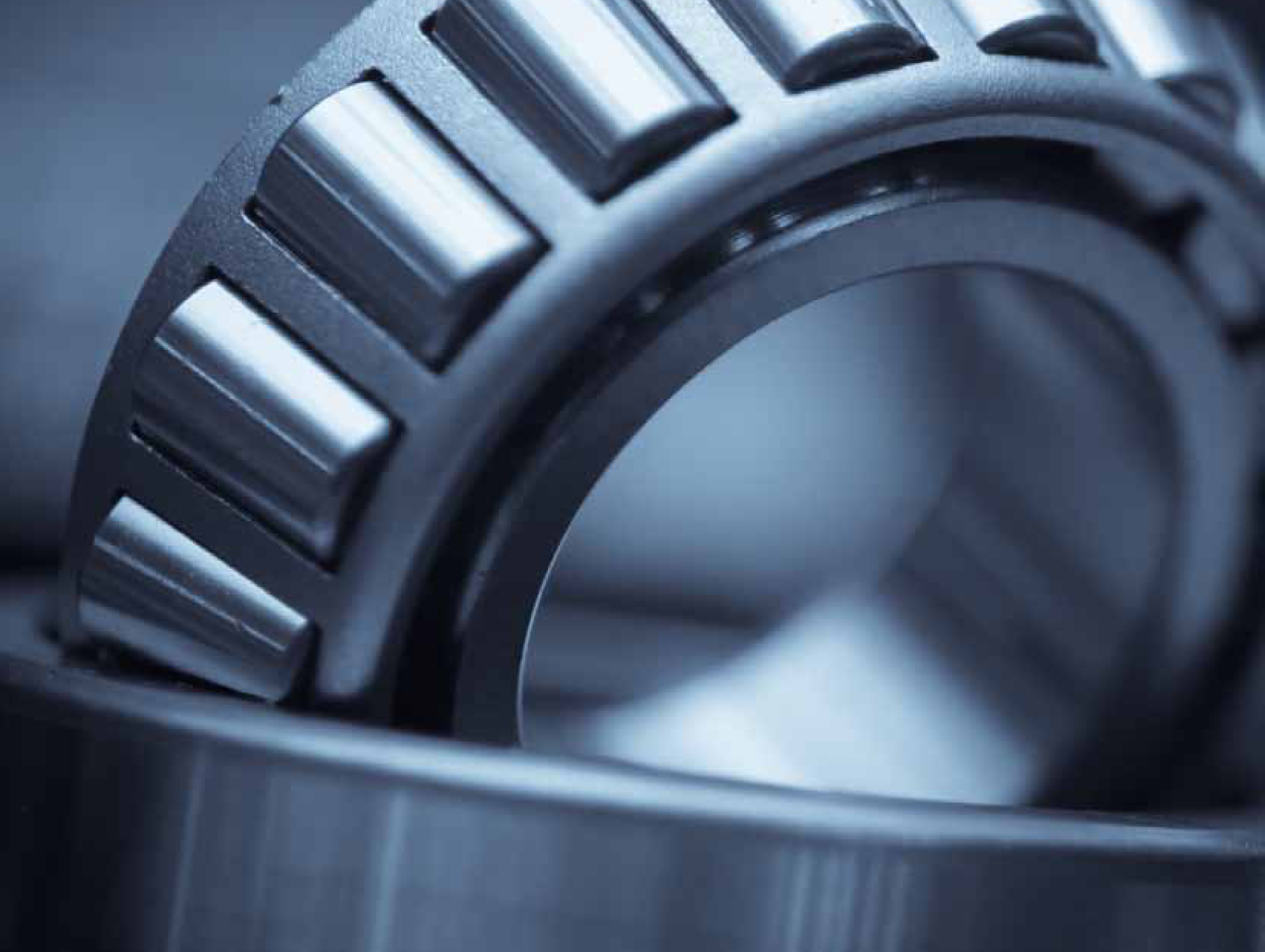
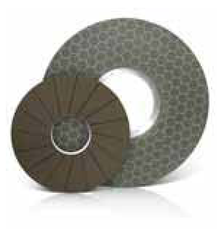
EHWA develops diamond and CBN tools for bearings and precision components. Applications range from bearing manufacture to aerospace. The programme combines grinding tools for rings and rollers with honing stones and accurate-profile dressers. The following mapping supports selection along the manufacturing sequence.
| Tool group | Machining task |
|---|---|
| Vitrified CBN grinding tools | Bearing diameters, raceways, lips and ring faces |
| CBN superfinish honing stones | Fine finishing of the bearing raceway |
| Rotary dressers | Profiles for ball, roller, hub and water-pump bearings |
| Metal cup dressers | Dressing for internal cylindrical grinding |
| Face and double-disc grinding tools | End faces of bearing rings and rollers |
| Taper-roller face grinding wheels | Taper-roller end faces |
| Profile dressers for linear guides | Ball raceways of guide blocks and rails |
| Profile dressers for ball screws | R-type ball raceway profile |


Vitrified CBN grinding tools for bearing rings
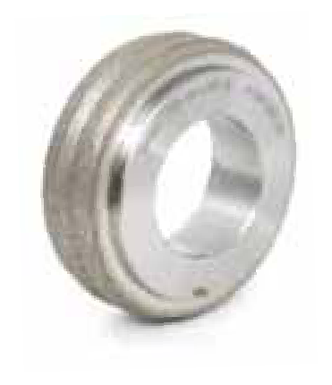
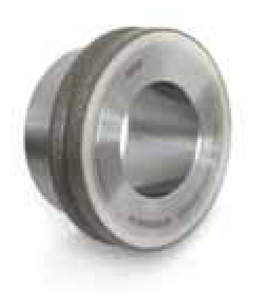
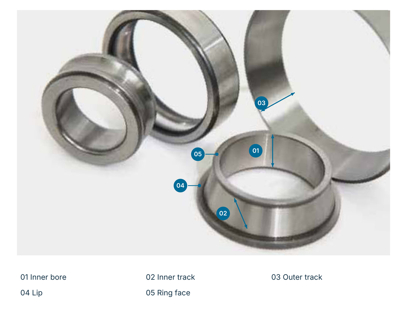
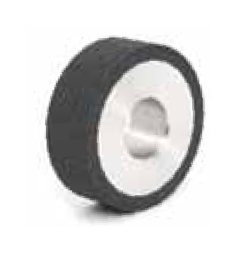
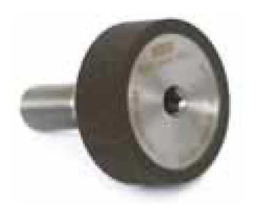
High removal rates and short cycles support economical bearing production. Reduced grinding force can limit mechanical and thermal loading of the bearing ring. Stable, accurate grinding supports surface finish, cylindricity and low dimensional deviation. Tools are available with ceramic cores, steel cores, steel quills or steel heads.
The process ranges describe this catalogue application. The dressing ratio is stated as 0.3–0.6; rotation direction and the precise speed definition are to be established during process design.
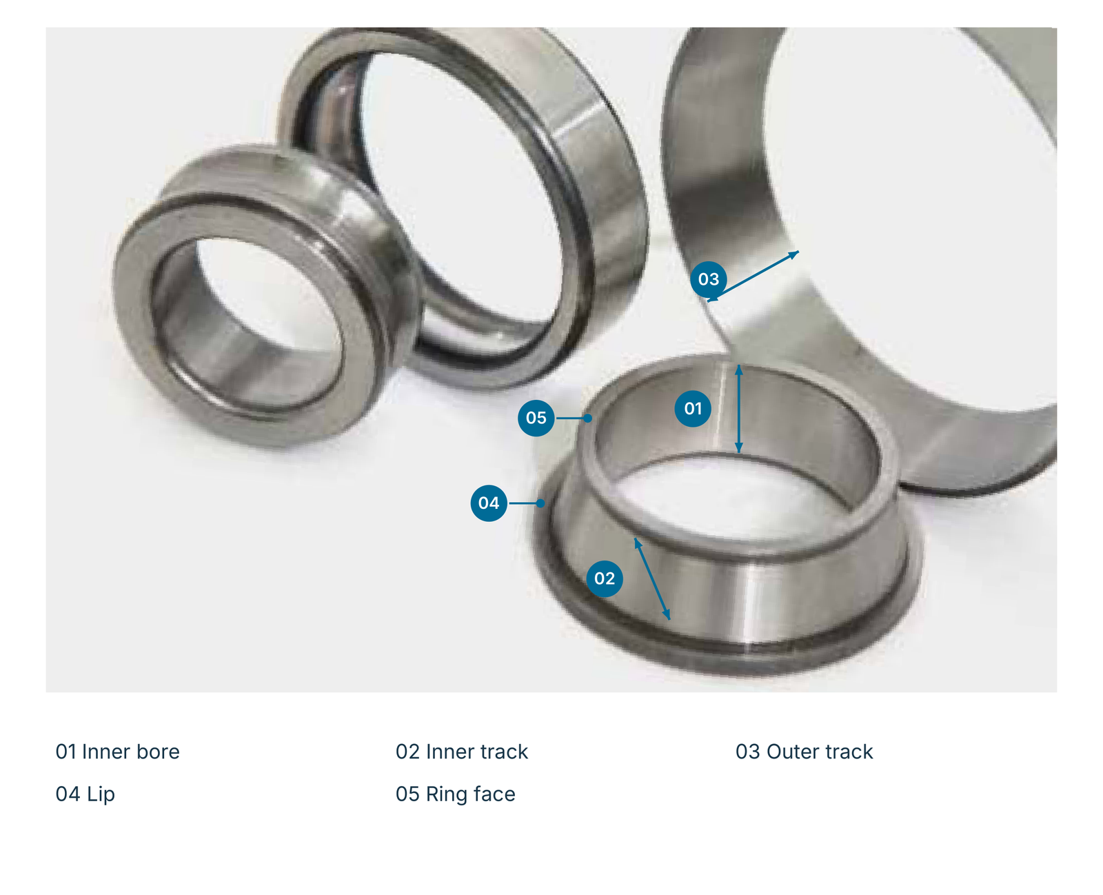
| Code | Grinding area |
|---|---|
| 01 ID | Inner-race internal diameter |
| 02 IR | Inner raceway |
| 03 OR | Outer raceway |
| 04 | Lip |
| 05 | Ring face |
| Parameter | Range / arrangement |
|---|---|
| Wheel speed | 30–80 m/s |
| Diameter removal | 0.1–0.35 mm D |
| Dressing amount | 5–30 µm |
| Dressing ratio | 0.3–0.6 |
| Dresser | Diamond rotary dresser |
| Coolant | Oil or emulsion |


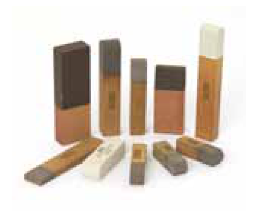
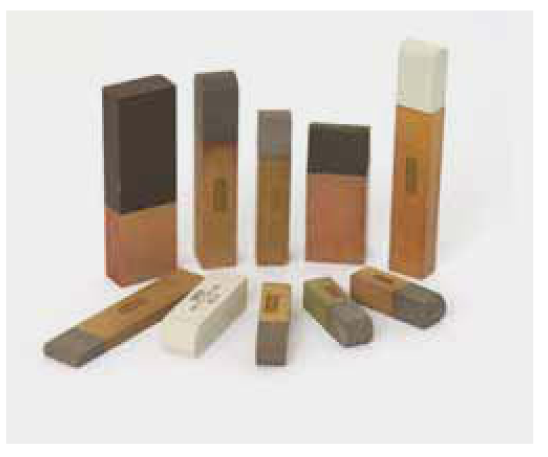
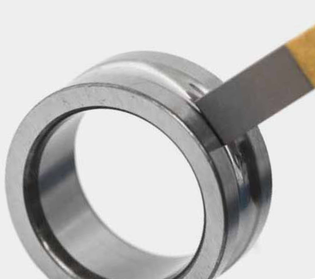
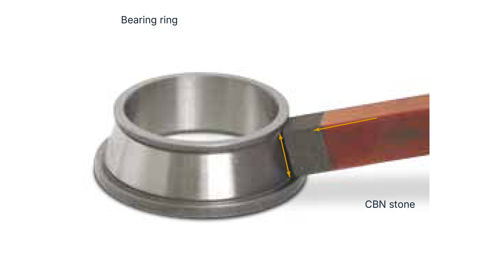
CBN honing stones for superfinishing
CBN honing stones can extend tool life compared with conventional stones, shorten the honing cycle and allow higher stock removal. Improved surface finish and consistent machining support lower scrap rates. The sulphur-free design is a specific feature of the presented programme.
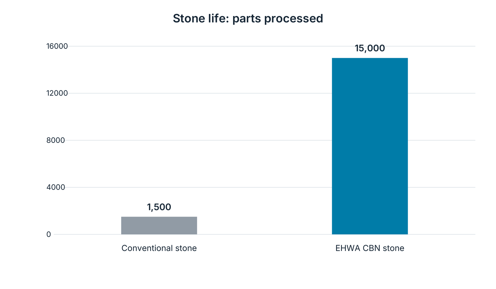
The catalogue states five to ten times the life of conventional stones. The illustrated taper-roller bearing raceway example compares 1,500 with 15,000 processed parts. These values belong to the application example; results in another process depend on workpiece and tooling conditions.
| Superfinishing example | Value |
|---|---|
| Workpiece speed | 100–200 rpm |
| Removal | 5 µm |
| Surface roughness | Ra 0.06 µm |
| Stone specification | B2400K120VHWPN |
| Conventional stone | 1,500 parts |
| EHWA CBN stone | 15,000 parts |

Rotary dressers for bearing profiles
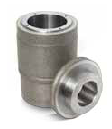
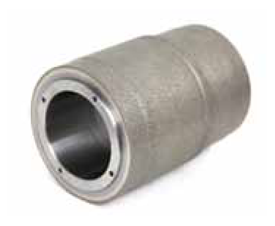
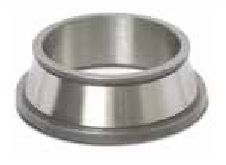
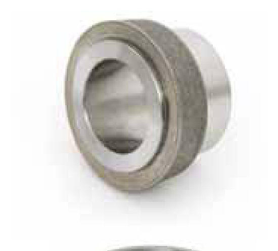
Diamond rotary dressers produce complex contours with high profile accuracy. Low dressing load supports dressing performance, while long tool life and short dressing cycles can improve economy. The illustrated dressers are intended for vitrified CBN grinding wheels. The three tool/workpiece pairs show water-pump bearings, ball bearings, and taper-roller and hub bearings.

Cup dressers for internal cylindrical grinding
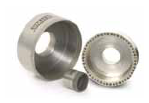
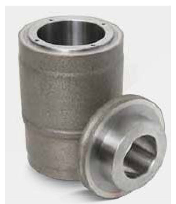
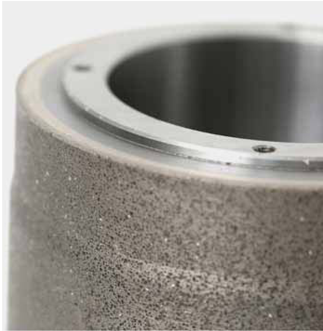
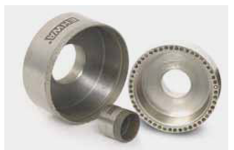
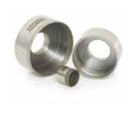
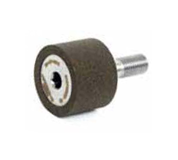
Cup dressers support accurate dressing and low grinding deviation after dressing. Long dressing intervals can reduce downtime. For the illustrated designs, the catalogue states 20,000–30,000 uses, depending on grinding-wheel size.
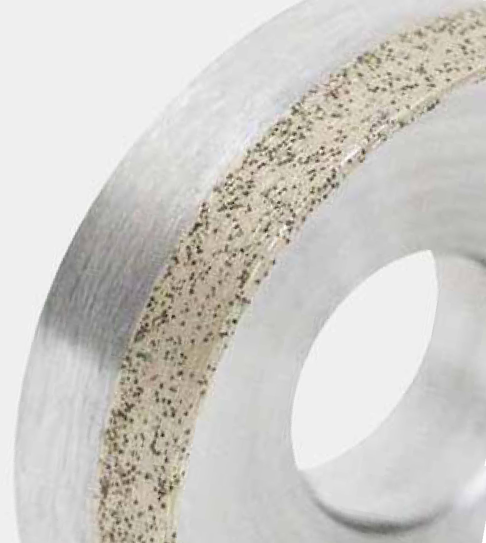
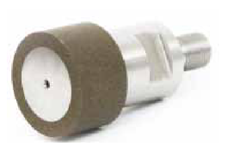
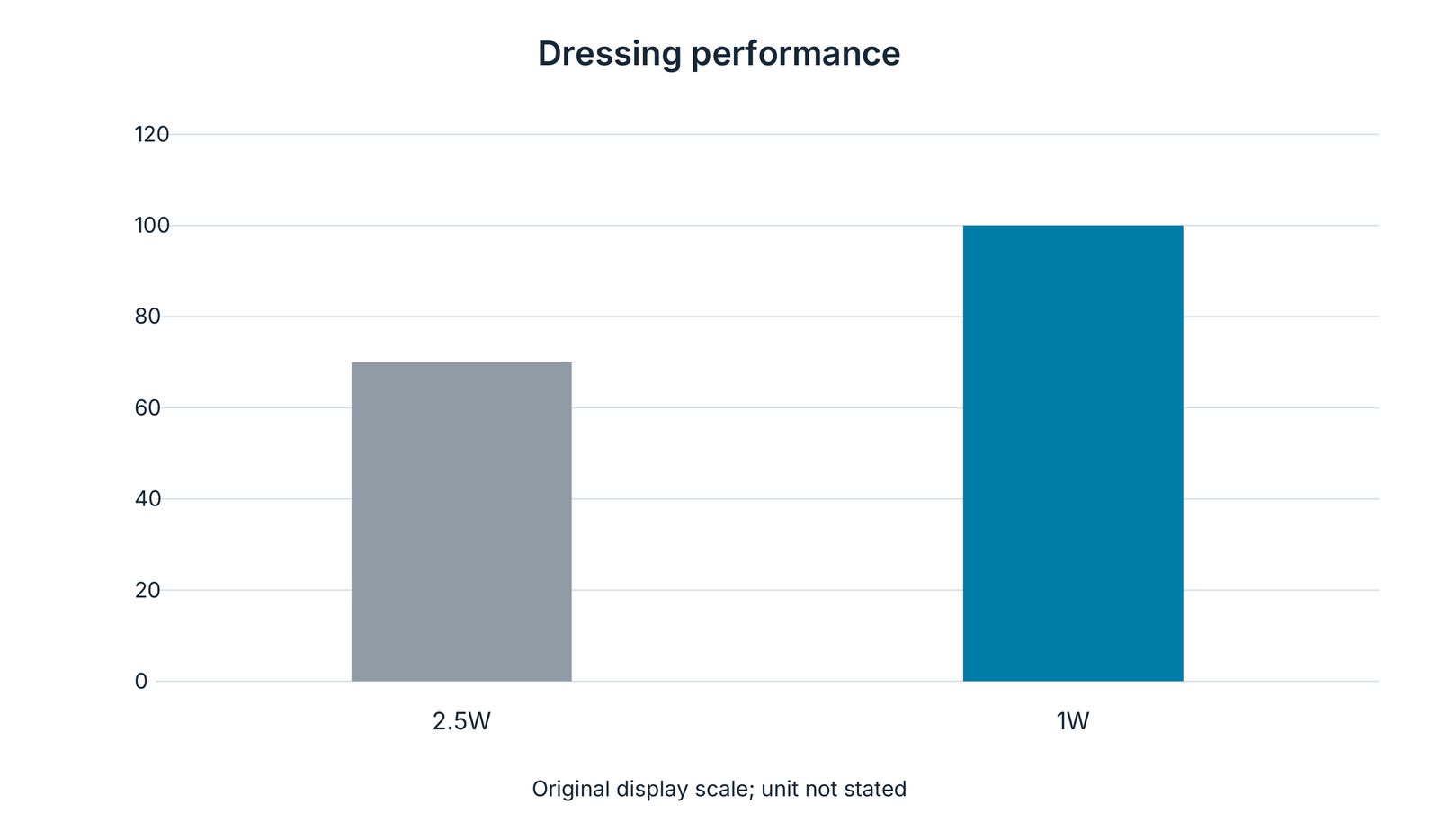
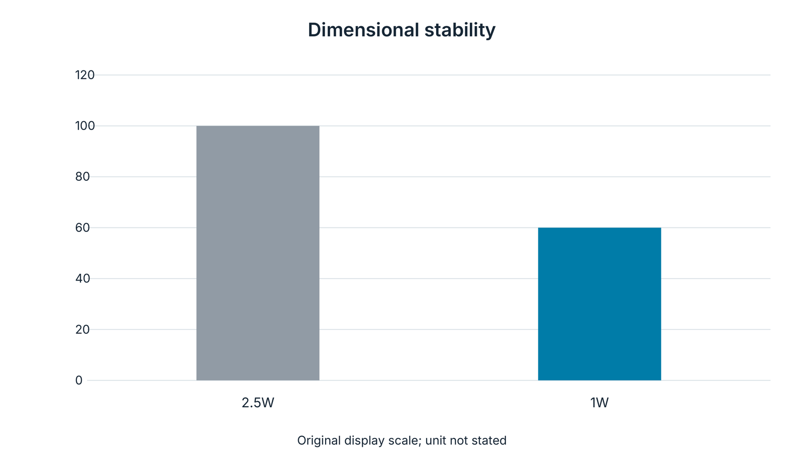
Diamond layer width affects dressing performance and dimensional stability. The comparison charts distinguish the designations 2.5W and 1W. Their scale has no stated unit and compares the illustrated variants. The application shows vitrified wheels with steel quills and steel heads.

Face and double-disc grinding of bearing components
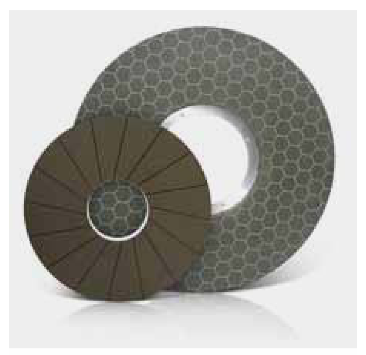
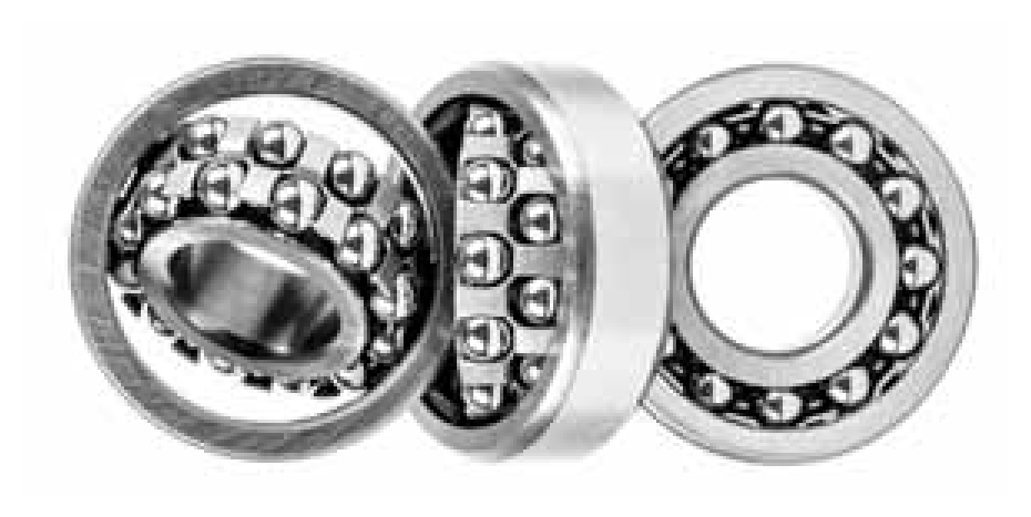
The tools machine end faces of bearing rings and rollers. Applications include needle-bearing and roller-bearing rollers, and inner and outer rings. Shorter cycle times support higher productivity, while long tool life can lower costs. Good surface finish remains a central quality objective. The illustrated tools show different sizes and designs for these tasks.

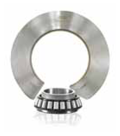
Face grinding wheels for taper rollers
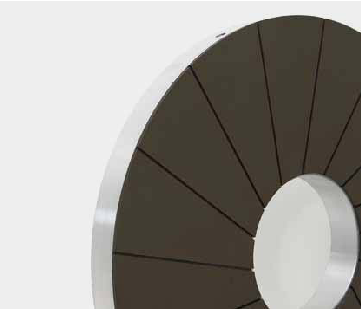
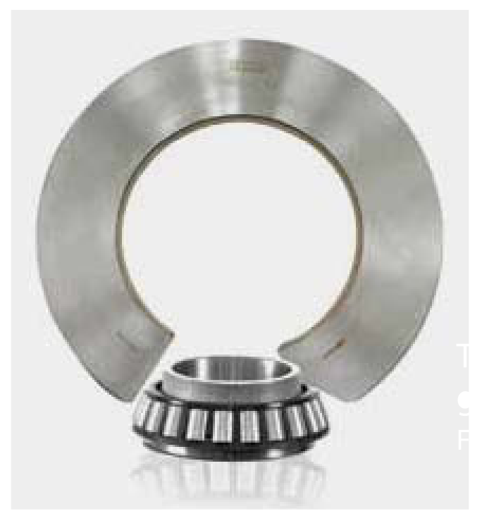
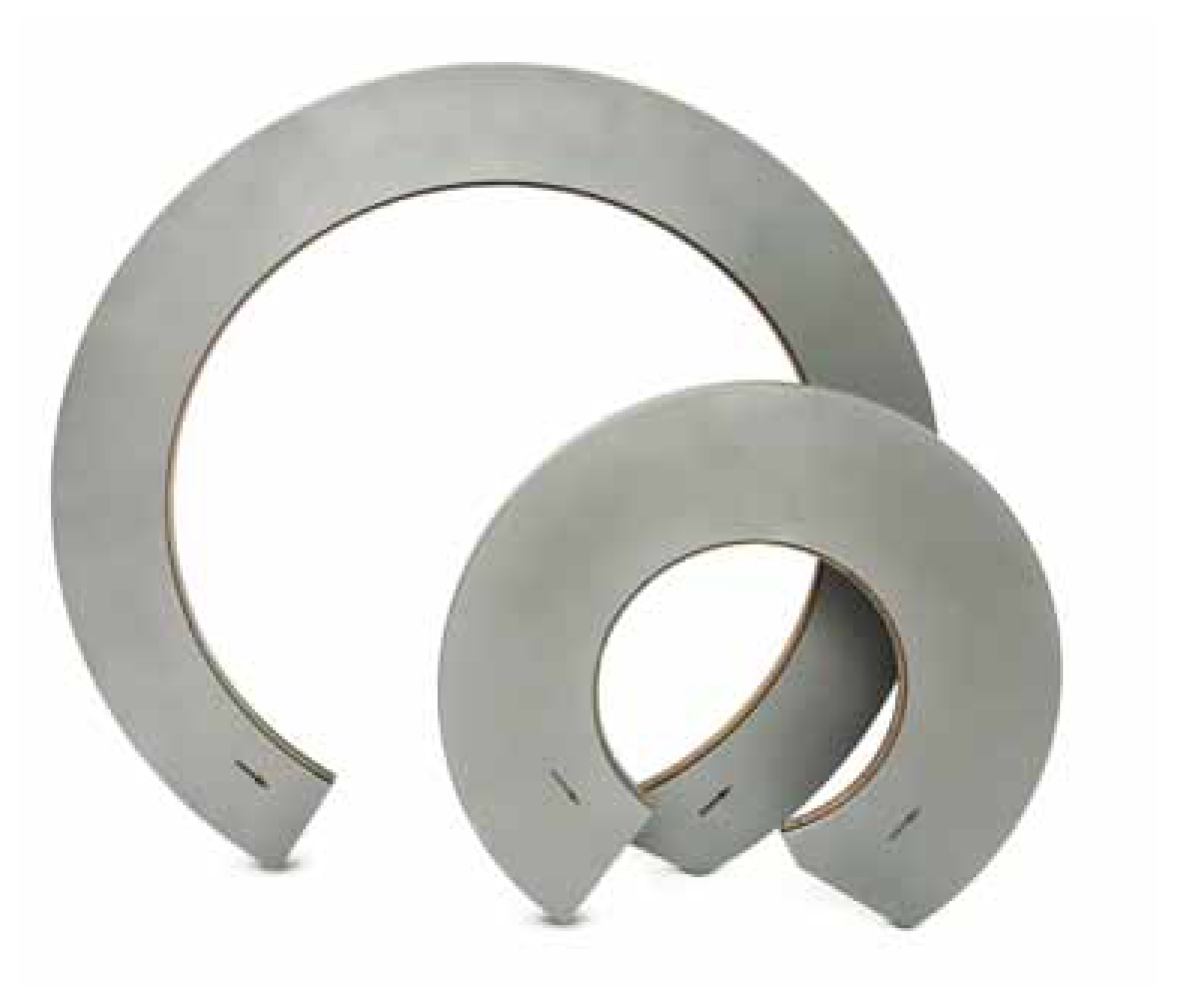
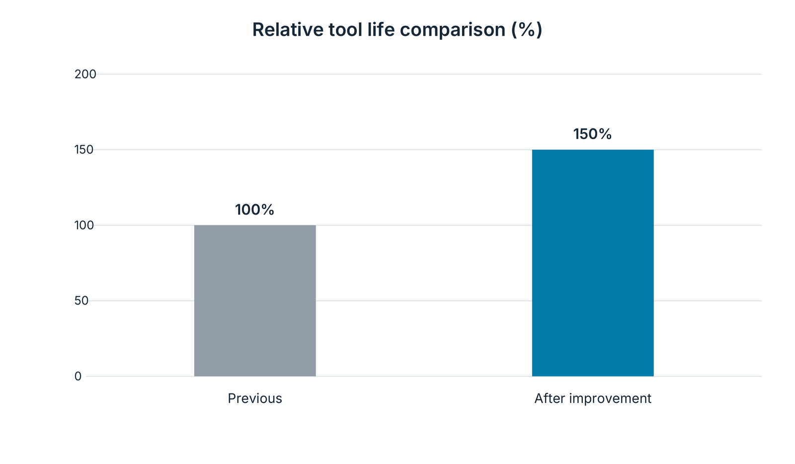
The illustrated wheels combine long tool life with high stock removal and good surface finish. This can reduce machining costs and increase productivity. The catalogue comparison shows relative life of 100% before improvement and 150% afterwards. It illustrates the presented development; absolute part counts and full test conditions are not stated.
Rotary dressers for linear guides
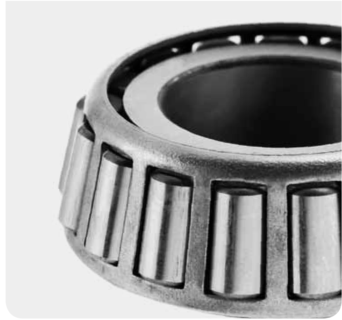
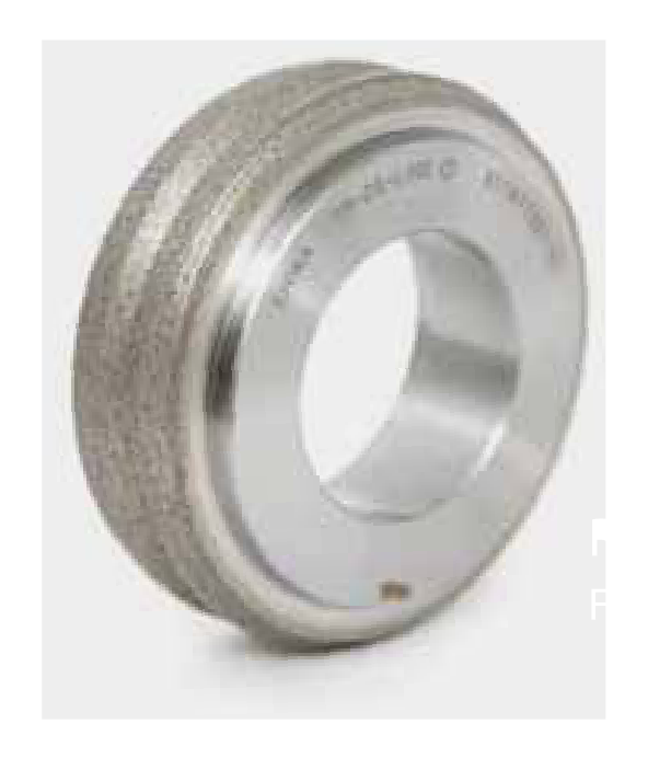
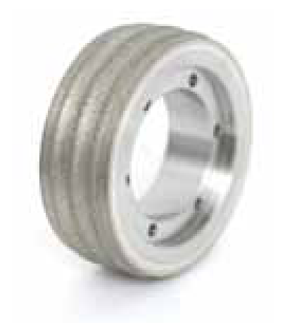
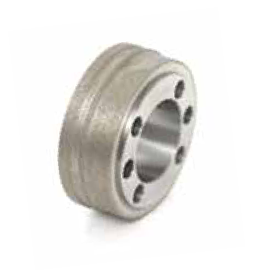
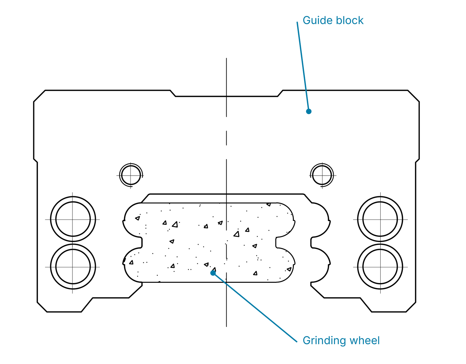
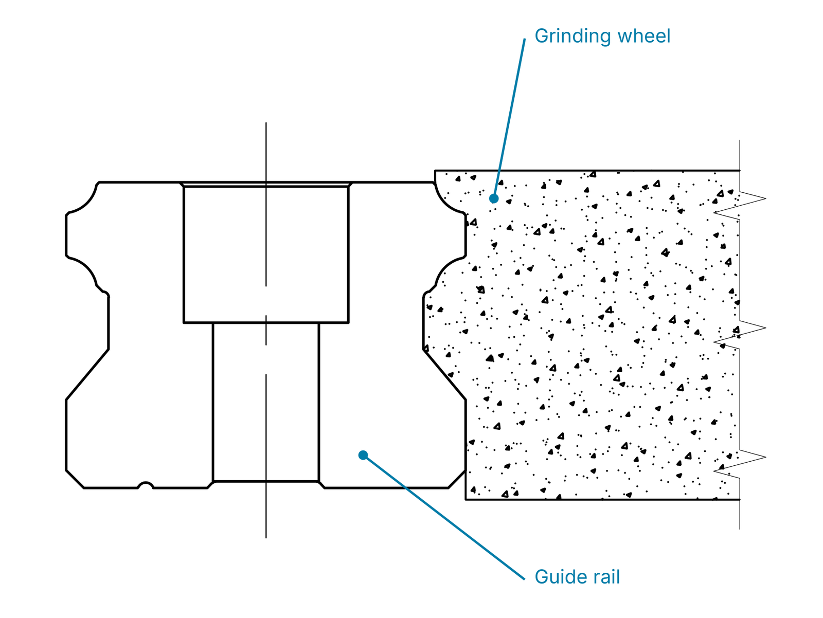
Linear guides consist of a guide block, rail and recirculating balls between them. They provide linear motion and are used, for example, in automotive manufacturing equipment. Rotary dressers profile CBN grinding wheels for the ball raceways in the block and rail.
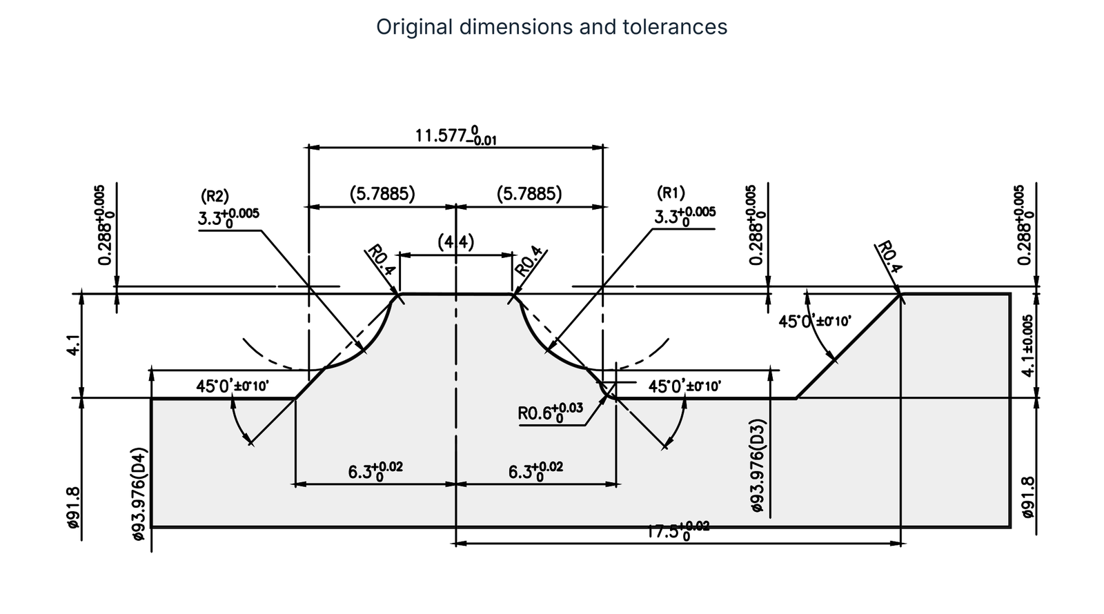
The two profile drawings show different geometries and tolerances. Dimension, radius and angle values belong to the respective drawing; the contact diagrams distinguish the grinding wheel from the guide block or rail.


Rotary dressers for ball screws
A ball screw converts rotary motion into linear motion. The screw and nut form the main assemblies, with balls transmitting movement through raceway contact. The illustrated dressers combine high profile accuracy and long tool life with high diamond concentration.
The R-type drawing contains radii, reference dimensions and angle tolerances for the illustrated example. V1 and V2 are stated as 45° +0/−2°. This tolerance differs from the linear-guide angle tolerances and belongs to the respective profile.

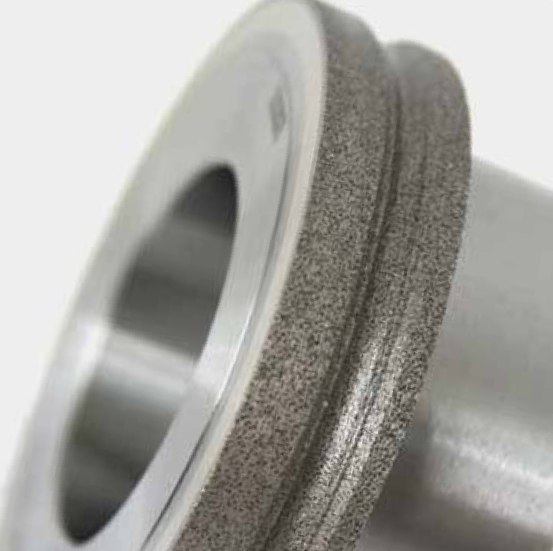


Diamond tools for glass and optics
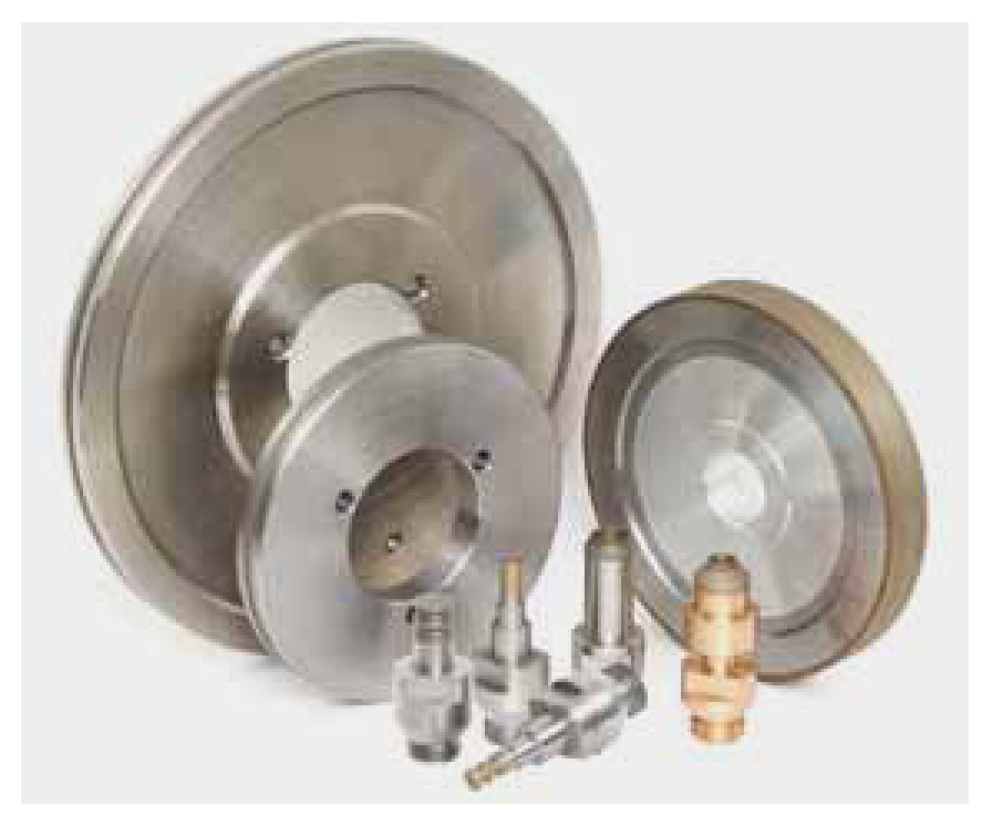
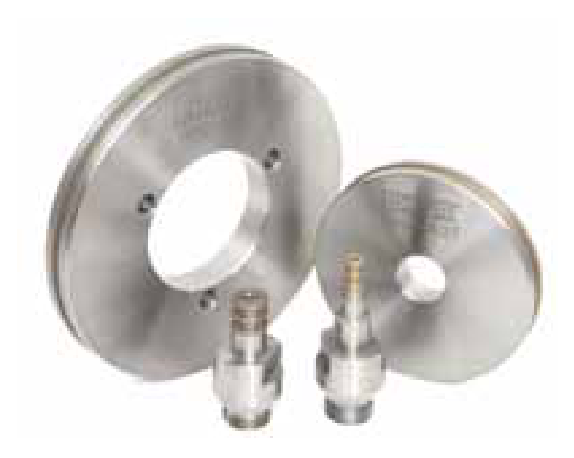
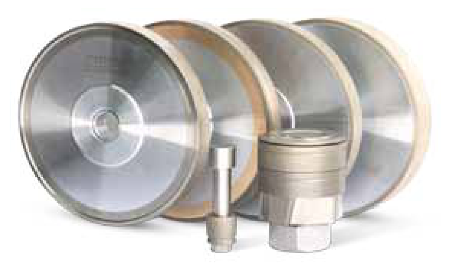
Diamond tools machine the hard, brittle materials used in glass and optics. The programme covers automotive safety glass, architectural glass, home-appliance glass, crystal, spectacle lenses and other optical lenses. Wheels and mounted tools are designed for edge, hole and lens machining. The following applications distinguish their bonds and process stages.

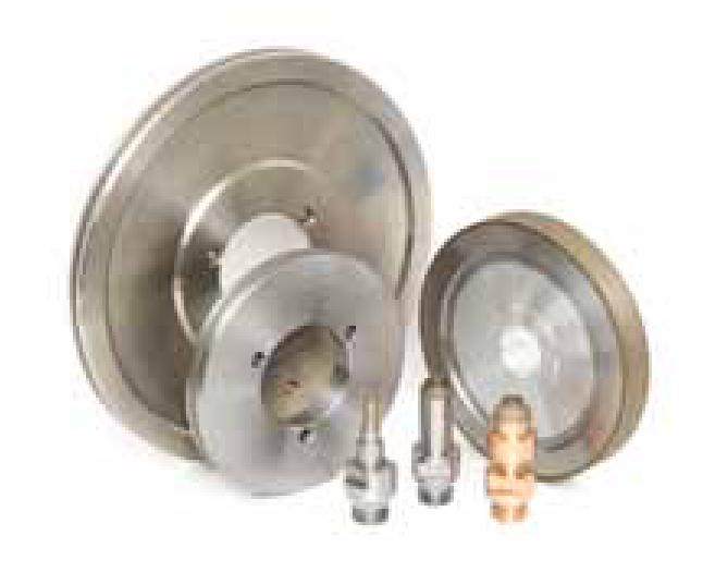
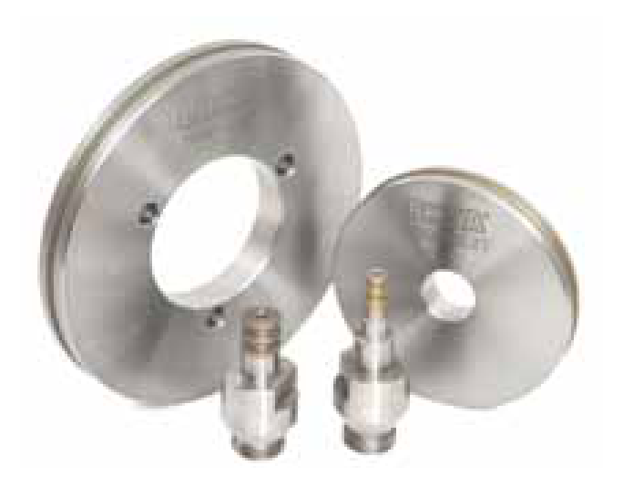

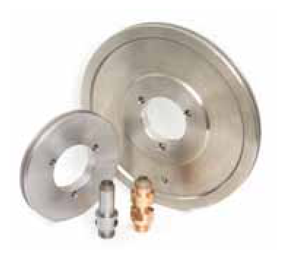

Edge grinding of automotive and home-appliance glass
Metal-bond diamond tools with MB, MC and MG bond series are specified for automotive glass. The range runs from a softer bond through a standard design to a harder bond. The micrographs show the respective structures.
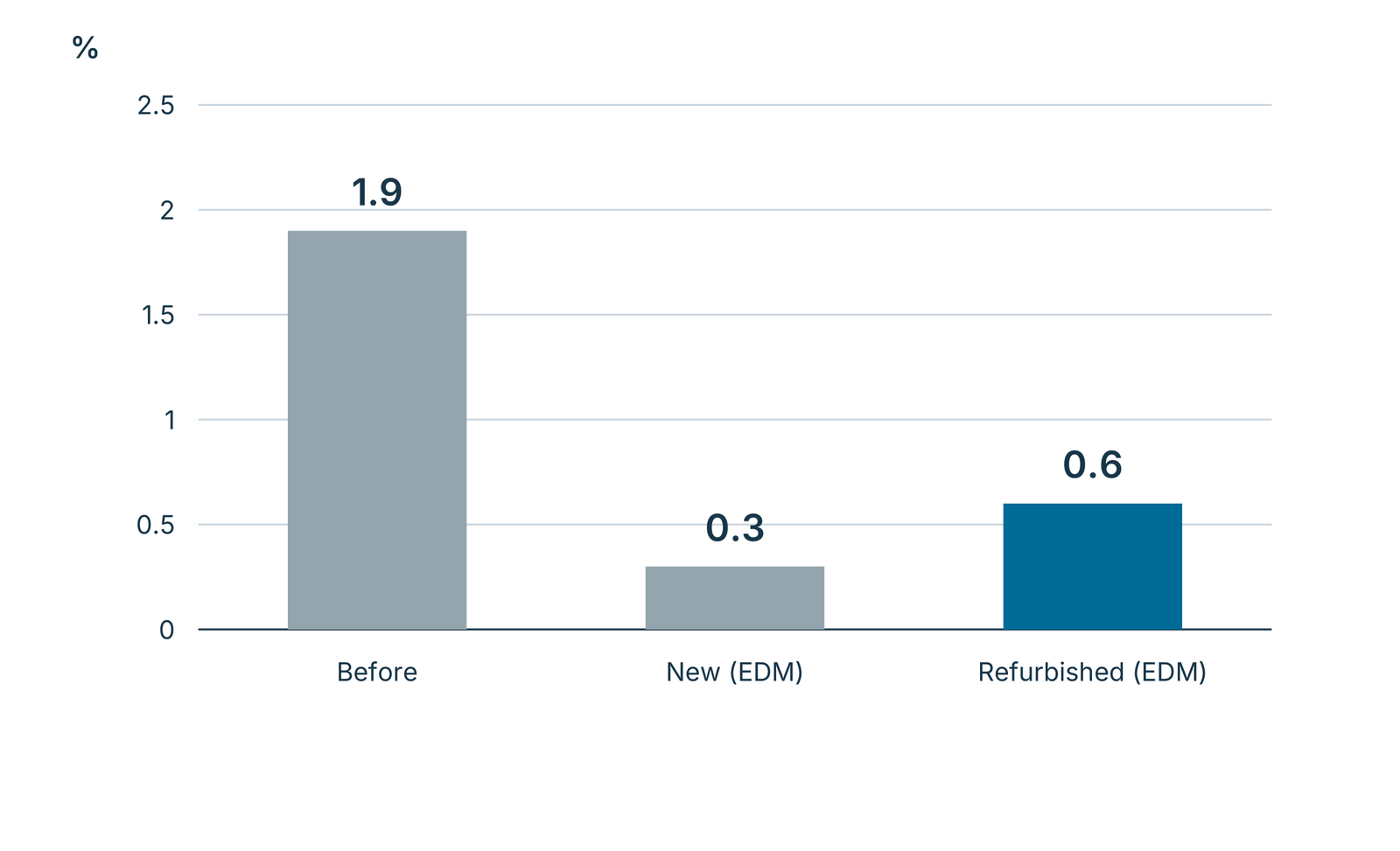
Home-appliance glass tools target good edge quality and low chipping rates. The example distinguishes the previous condition, a new EDM tool and a refurbished EDM tool. The illustrated chipping rates are 1.9%, 0.3% and 0.6%, respectively. The refurbished design also remains below 1% in this example; this describes the comparison rather than a universal scrap limit.
| Application | Grit | Bond | Feature |
|---|---|---|---|
| Automotive glass | D107–D30 | MB series | Softer |
| Automotive glass | D107–D30 | MC series | Standard |
| Automotive glass | D107–D30 | MG series | Harder |



Optical lenses: process stages and tool forms
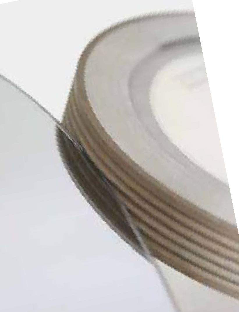
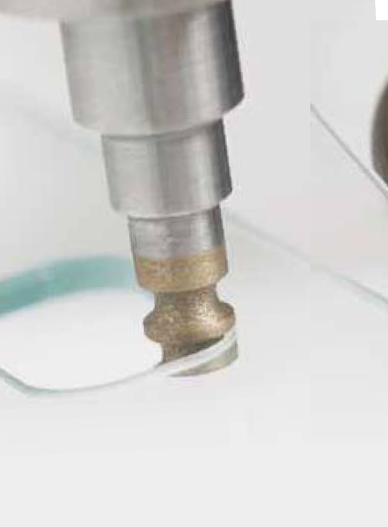
The optical-lens programme covers roughing, finishing and polishing. The specification distinguishes the GL and PL application designations used in the catalogue. BSL designs are illustrated with slotted or continuous layers.
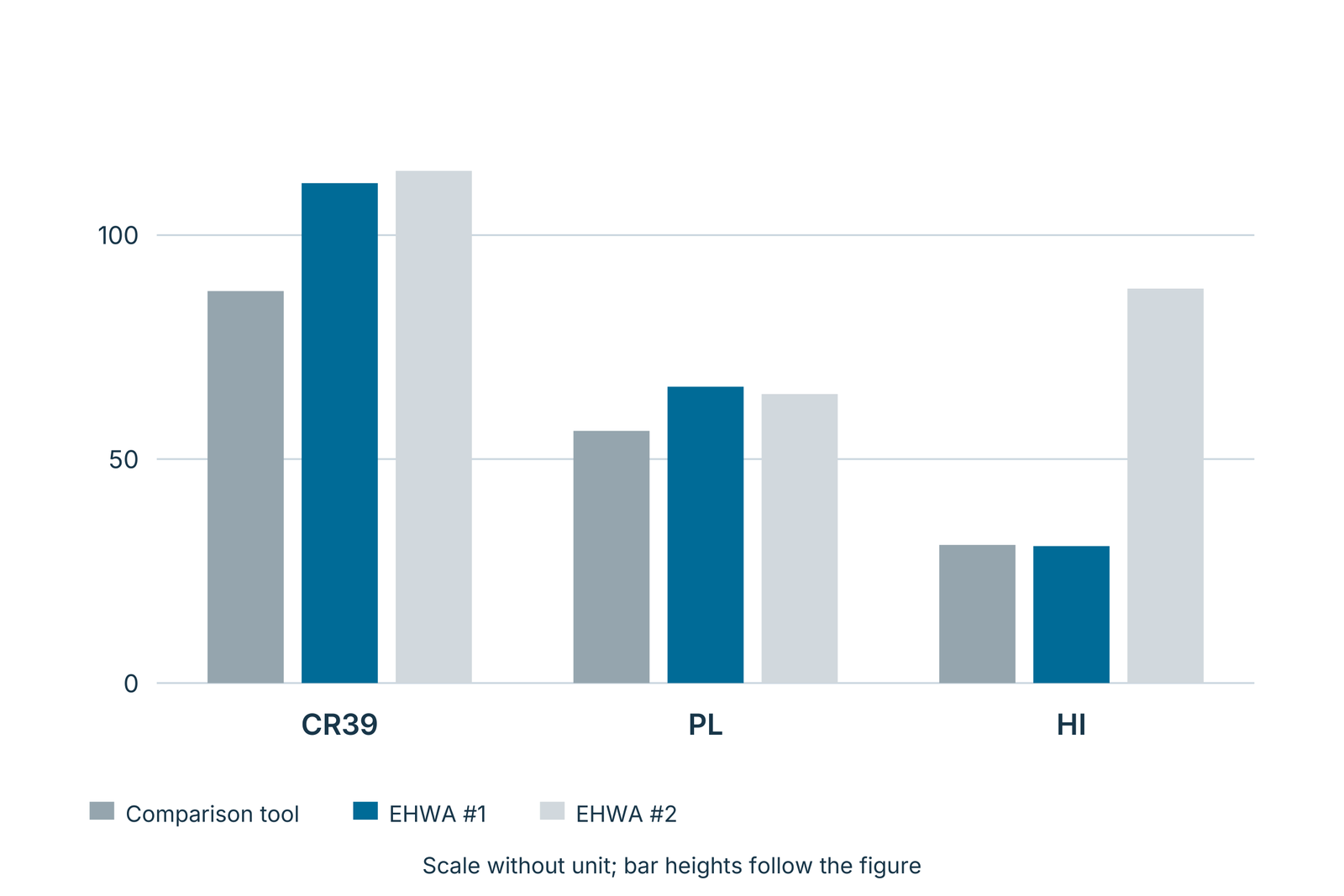
The comparison for CR39, PL and HI shows a comparison tool, EHWA #1 and EHWA #2. Results differ by material designation; the scale has no stated unit. Three further application images show side-mirror edge grinding, glass-hole grinding and home-appliance glass machining.
| Process | Type | Grit |
|---|---|---|
| Roughing (GL) | MD-1A1 | D251–D151 |
| Roughing (PL) | MD-BSL | D301–D151 |
| Finishing | MD-1EE6Y | D46–D30 |
| Polishing | MD-1EE6Y | D2 |




Grinding tools for cutting-tool manufacture
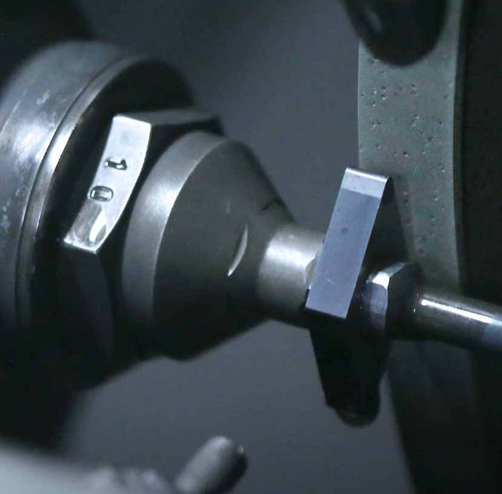
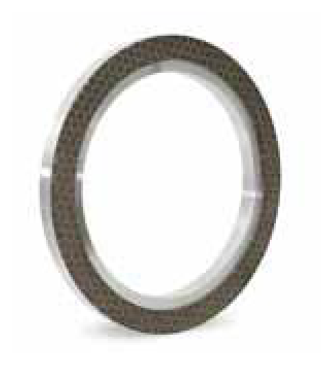
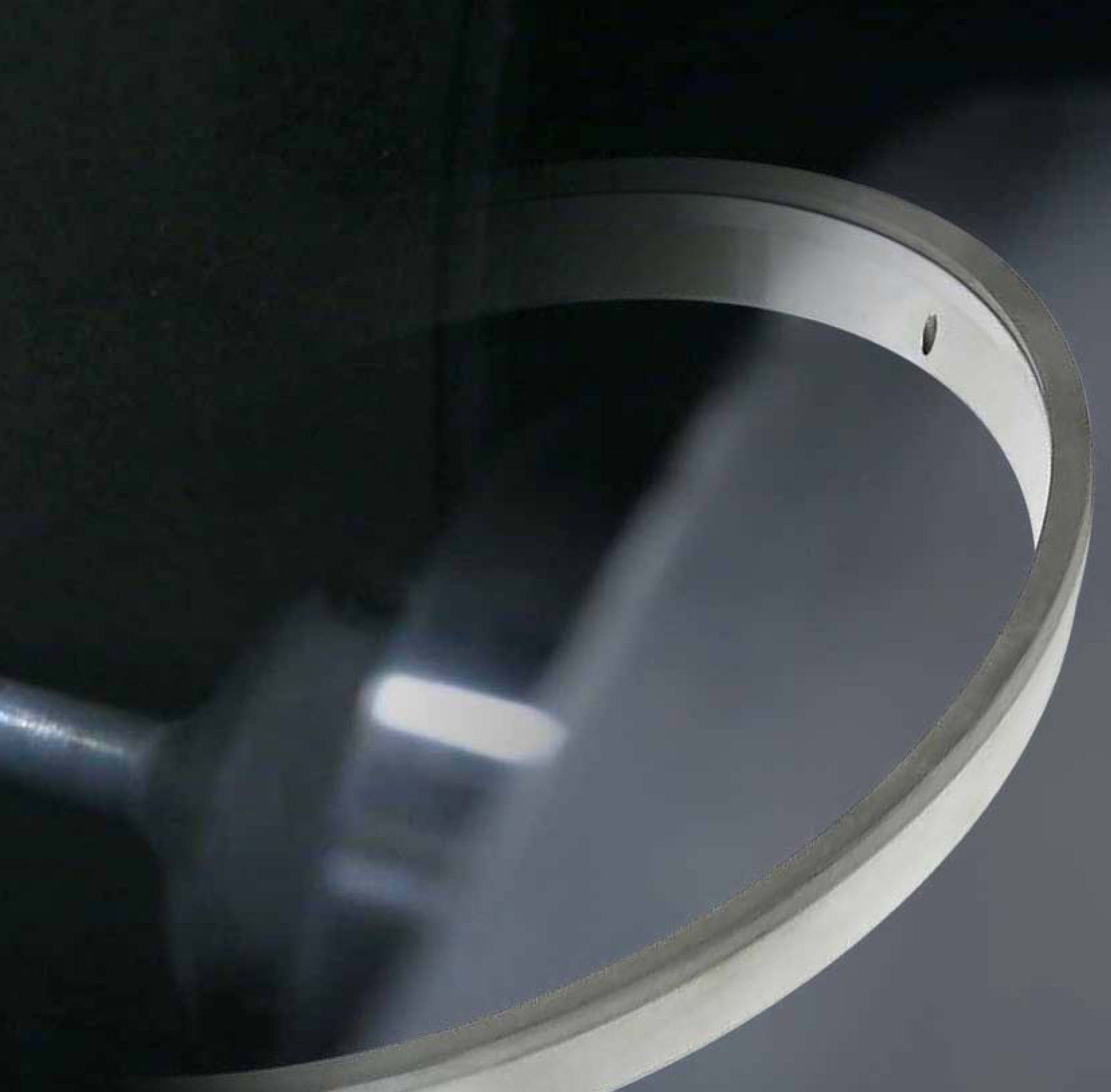
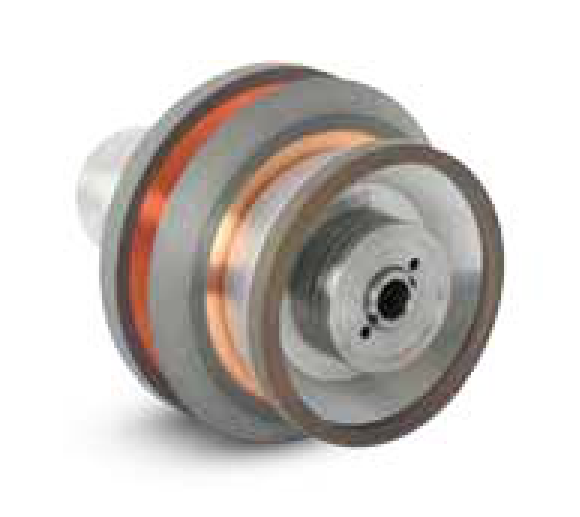
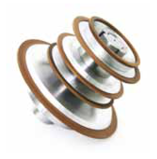
The programme supports manufacturing and regrinding of cutting tools made from high-speed steel, carbon steel, ceramics, carbide, PCD and PCBN. Abrasive and bond selection depends on the tool material and process. Tungsten-carbide-based tools are an important application for diamond grinding wheels.
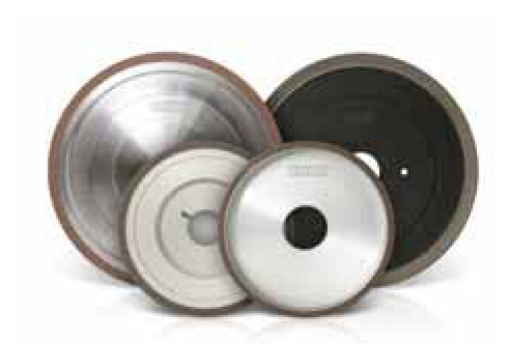
Tool forms range from peripheral and face grinding wheels for inserts through wheel packs for rotating tools and microtools to wheels for tipped saws.

Cutting inserts: periphery, top and bottom faces
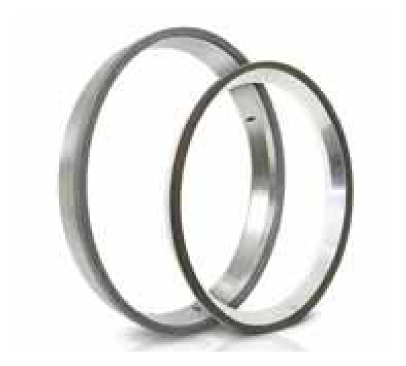
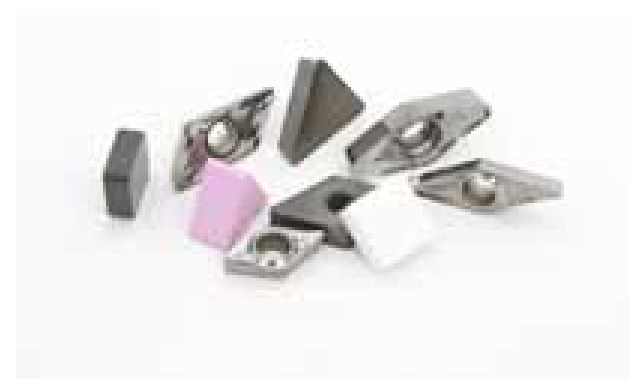
EHWA provides grinding wheels for inserts made from carbide, ceramics, cermet, PCD and PCBN. Specifications consider cycle time and dressing intervals. The aim is consistent inserts with good surface finish and edges with minimal chipping.
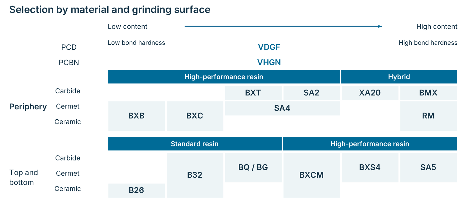
In peripheral grinding, high feed rates support short cycles; small edge chips and long dressing intervals are further advantages. Top and bottom grinding targets short cycles, long dressing intervals and high dimensional stability. The bond matrix maps the tool materials to bond series. Its arrow describes increasing content without specifying a quantitative composition.
| Operation | Machines named in the catalogue |
|---|---|
| Peripheral grinding | Agathon, Wendt, Waida, Ewamatic, Ewag |
| Top and bottom grinding | Stahli, Peter Wolters, Wendt WBM, Agathon T&B, Fujisanki |
Cutting inserts: three separate application examples
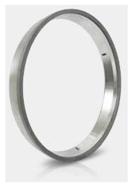
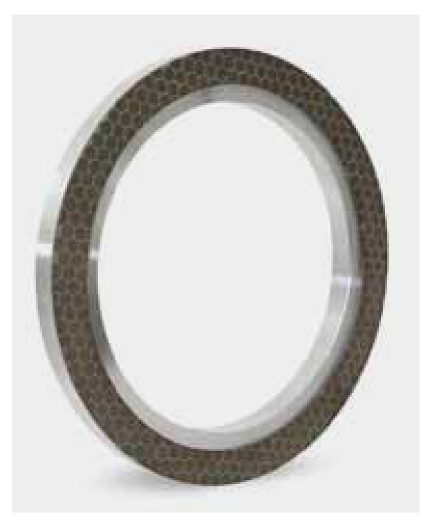
High-temperature polyimide bonds are used for peripheral grinding. Hybrid and soft-metal bonds extend the options for shorter cycles, small edge chips and stable dimensions. The following examples use different workpieces, machines and specifications.
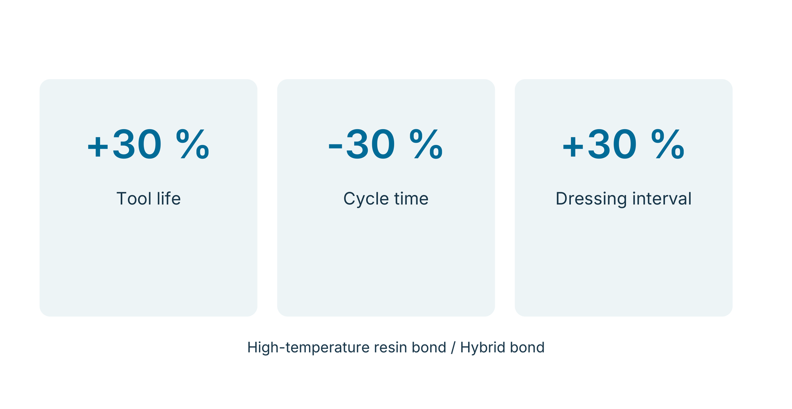
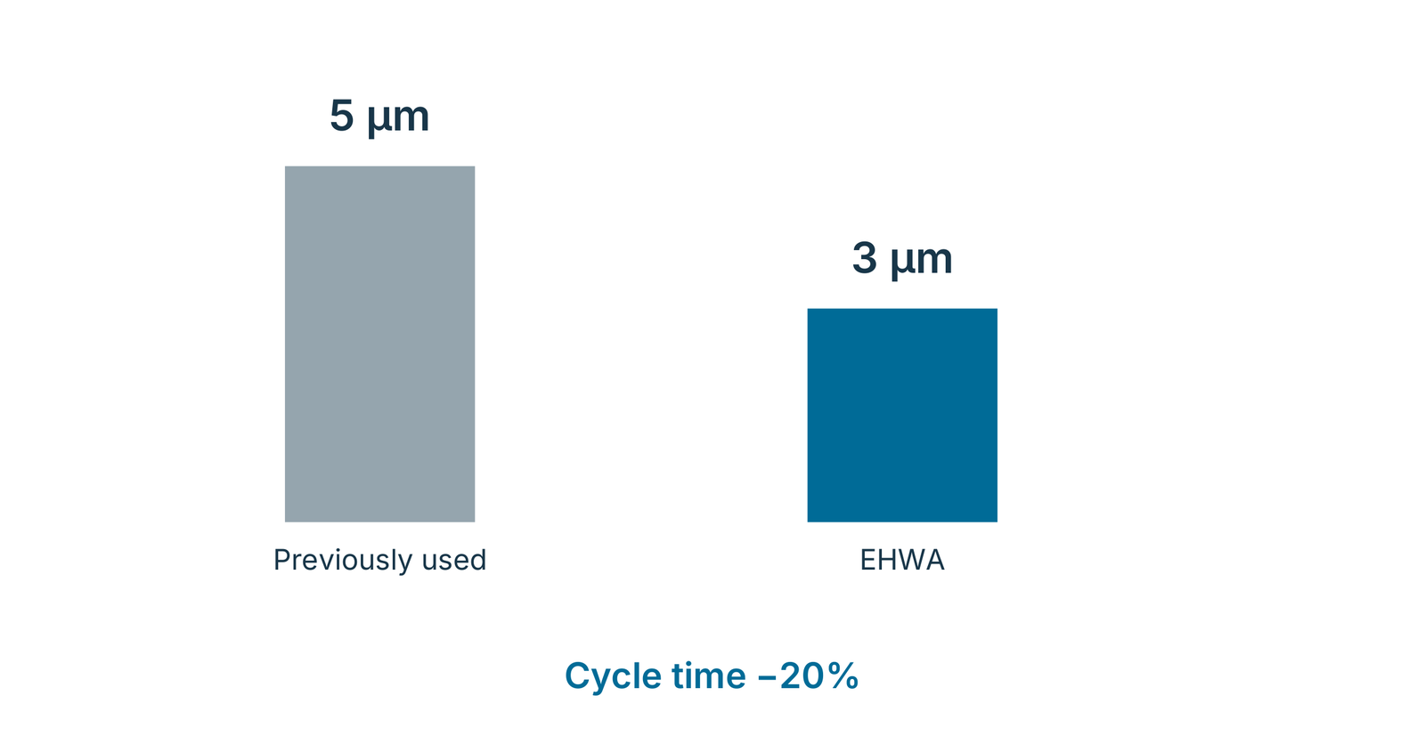
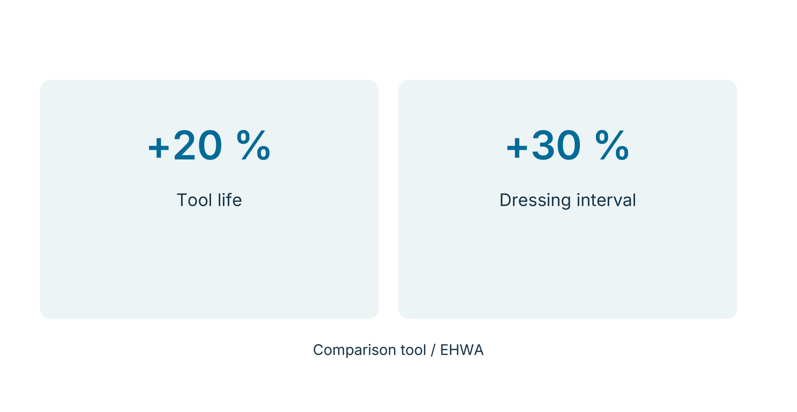
In the carbide comparison, the hybrid bond achieves 30% longer life, 30% shorter cycle time and 30% longer dressing intervals than the high-temperature resin bond. In the PCBN example, chip size falls from 5 to 3 µm and cycle time decreases by 20%. In face grinding, tool life rises by 20% and the dressing interval by 30% compared with the reference tool. Each improvement belongs to its respective illustrated test.
| Parameter | Periphery: carbide | Periphery: PCBN | Top and bottom: carbide |
|---|---|---|---|
| Machine | Wendt 715 WAC Quattro | Agathon | Wendt WBM221-Duo Lift |
| Workpiece | Carbide insert | PCBN insert | Various carbide inserts |
| Wheel speed | 20 m/s | 18 m/s | — |
| Typ | RD-11A2 | VD-11A2 | RD-2A2T |
| Specification | 400D-39T-10W-6X-355.06H | 400D-39T-15W-6X-355.06H; D6M120VHGN | 501D-5X-40W; D126BXS4 |
| Compared bonds | D46 high-temperature resin / D40 hybrid | — | — |
| Coolant | — | — | Oil |
Bonds for rotating tools
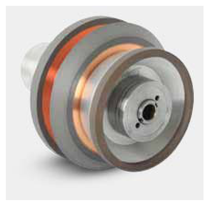
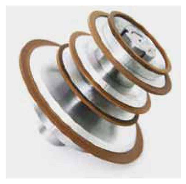
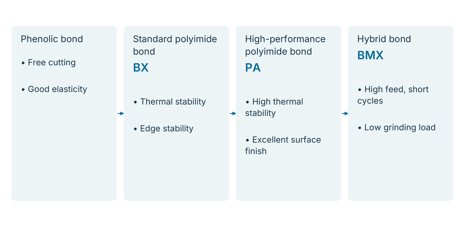
Polyimide bonds have higher thermal stability than the phenolic and epoxy bonds compared here. In suitable processes, this supports grinding performance and tool life. Hybrid bonds combine polyimide and metal components, bringing together grinding performance and elasticity with wear resistance and thermal stability.
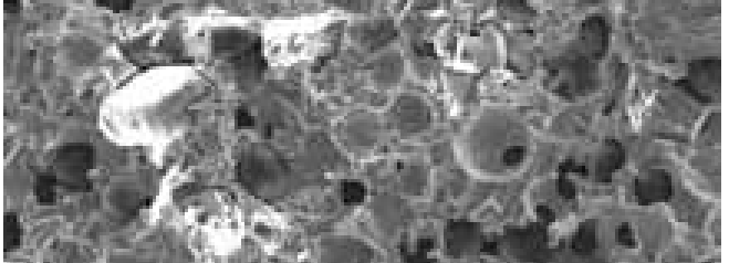
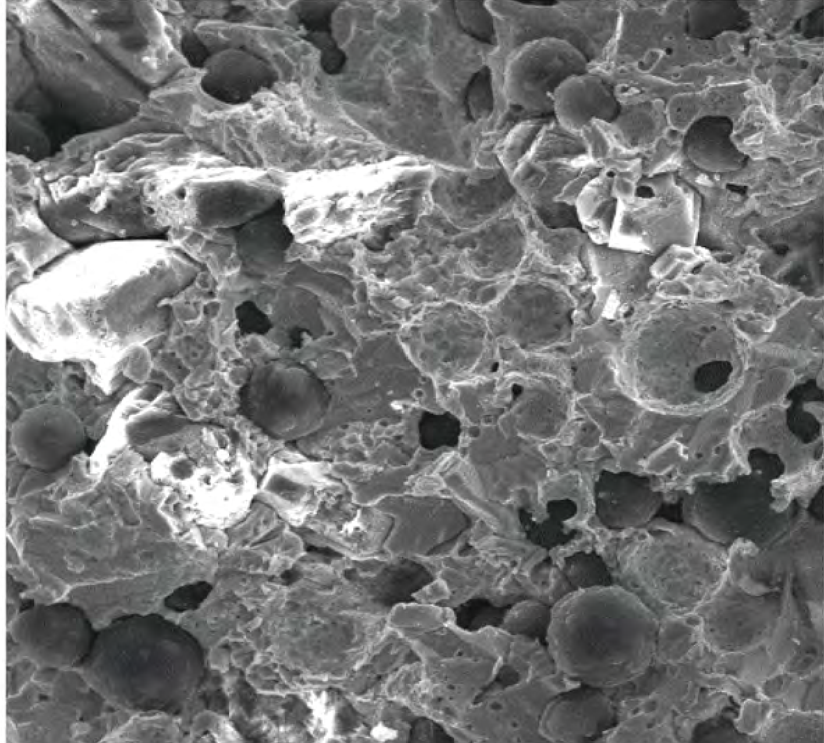
The pore structure of a porous hybrid bond helps diamond protrusion and coolant access. Lower grinding load can allow a higher permissible feed rate and shorter cycle time. The overview compares phenolic, standard polyimide, high-performance polyimide and hybrid bonds and their respective features.
Drills, endmills, microtools, taps and rotary burrs
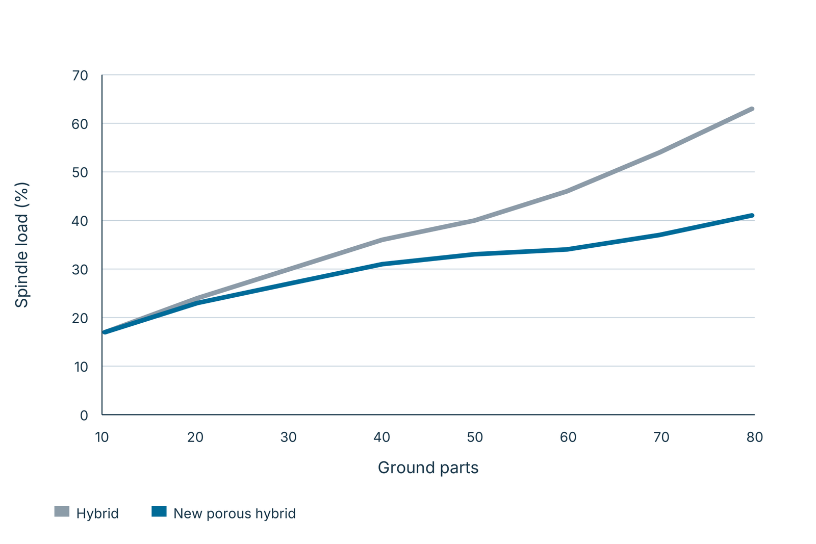
The drill/endmill example compares spindle load for a hybrid bond and a new porous hybrid bond over the number of ground parts. In the illustrated trend, load increases less strongly with the porous design. Test conditions are listed in the table.
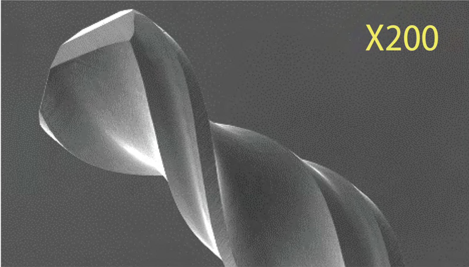
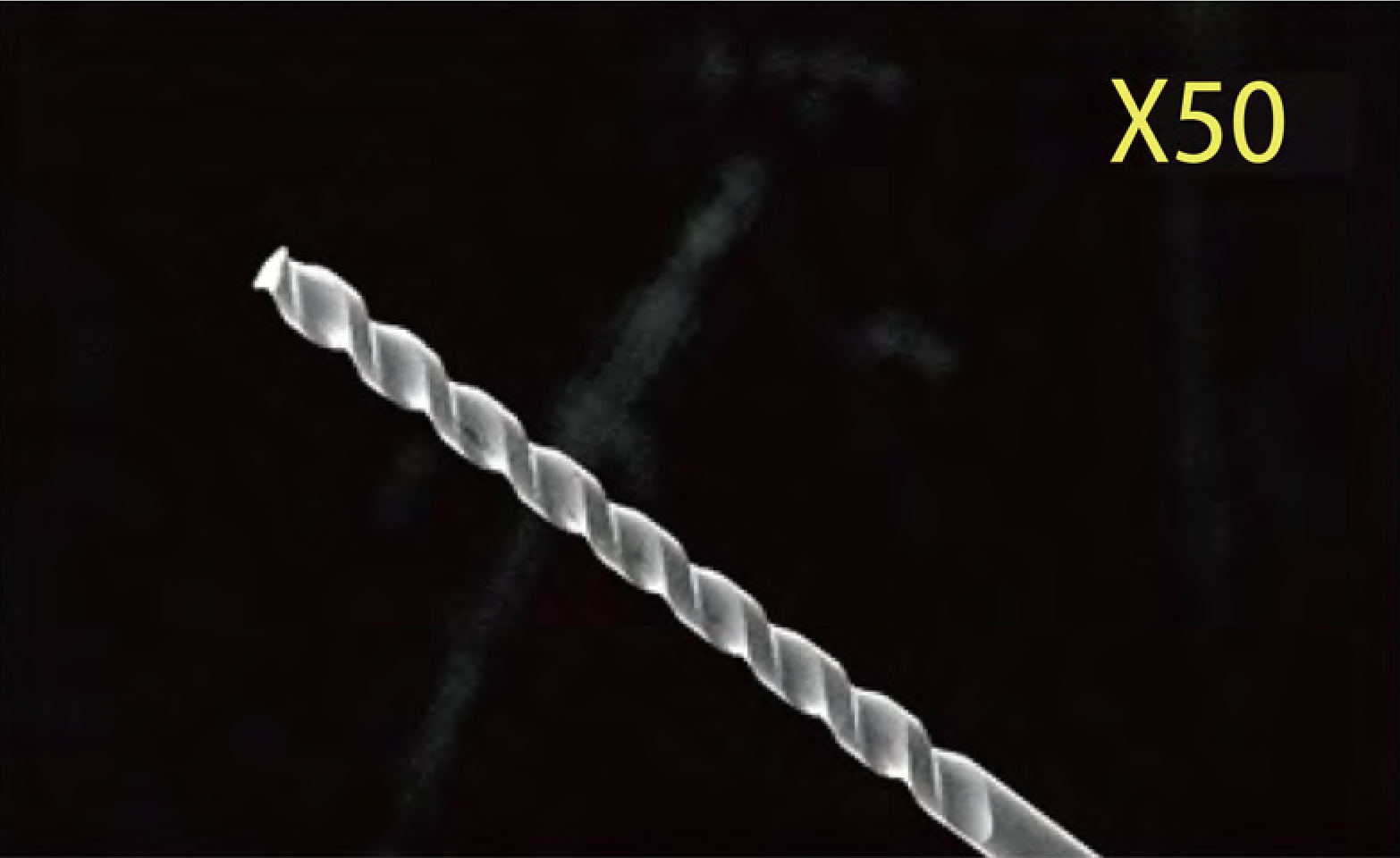
For precision tools and microtools, priorities include productivity at economical tooling cost, good surface and cutting-edge quality, and stable edges. The two microtool images are marked ×200 and ×50.
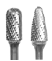
For taps, the illustration shows a VB-1A1 grinding wheel and an R/D-RR dresser. Rotary burrs are machined with MD-1V1 and the ME4 bond series.
| Drill/endmill example | Test condition |
|---|---|
| Machine | ANCA FX7 (19 kW) |
| Material / tool | Carbide Ø12–50 mm (LOF), 2 flutes (K10) |
| Wheel speed | 18 m/s |
| Feed rate | 120 mm/min |
| Depth of cut | 2.4 mm |
| Application | Type / specification | Bond |
|---|---|---|
| Tap: grinding | VB-1A1 | — |
| Tap: dressing | R/D-RR | — |
| Rotary burr | MD-1V1; 110D–160D / 30V–60V | ME4 series |


Circular saws, hob cutters and broaches
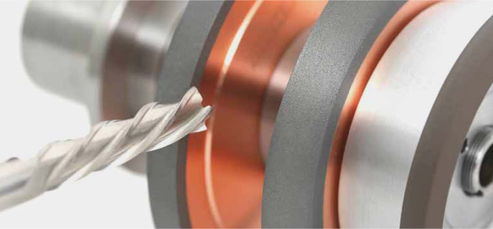
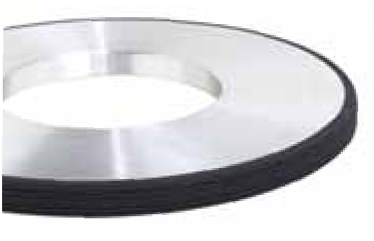
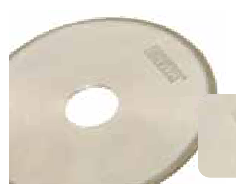
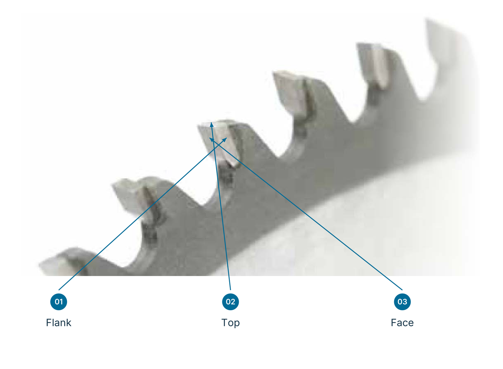
For carbide-tipped circular saws, the programme distinguishes flank, top and face grinding. Long tool life, short cycles, good surface finish and high dimensional stability support saw-tooth manufacture and resharpening. Image codes 01, 02 and 03 map the machining surfaces to their corresponding wheels.
For profile grinding of HSS saw blades, RB-14F1/S with CBN107 is specified. The dimensional designations D, x1, x2 and U are retained in the selection below. Application images also show grinding of hob cutters and broaches.
| Type | D | x1 | x2 | U | Bond |
|---|---|---|---|---|---|
| RB-14F1/S | 150 | 6 | 8 | 1, 1.3, 1.6, 2, 2.5 | Hardened resin bond |
| RB-14F1/S | 150 | 6 | 10 | 3 | Hardened resin bond |
| RB-14F1/S | 150 | 8 | 12.5 | 3.5 | Hardened resin bond |
| RB-14F1/S | 150 | 8 | 12.5 | 4 | Hardened resin bond |
| RB-14F1/S | 150 | 10 | 15 | 5, 6 | Hardened resin bond |
| RB-14F1/S | 200 | 6 | 8 | 1, 1.3, 1.6, 2, 2.5 | Hardened resin bond |
| RB-14F1/S | 200 | 6 | 10 | 3 | Hardened resin bond |
| RB-14F1/S | 200 | 8 | 12.5 | 3.5 | Hardened resin bond |
| RB-14F1/S | 200 | 8 | 12.5 | 4 | Hardened resin bond |
| RB-14F1/S | 200 | 10 | 15 | 5, 6 | Hardened resin bond |
Tools for medical components
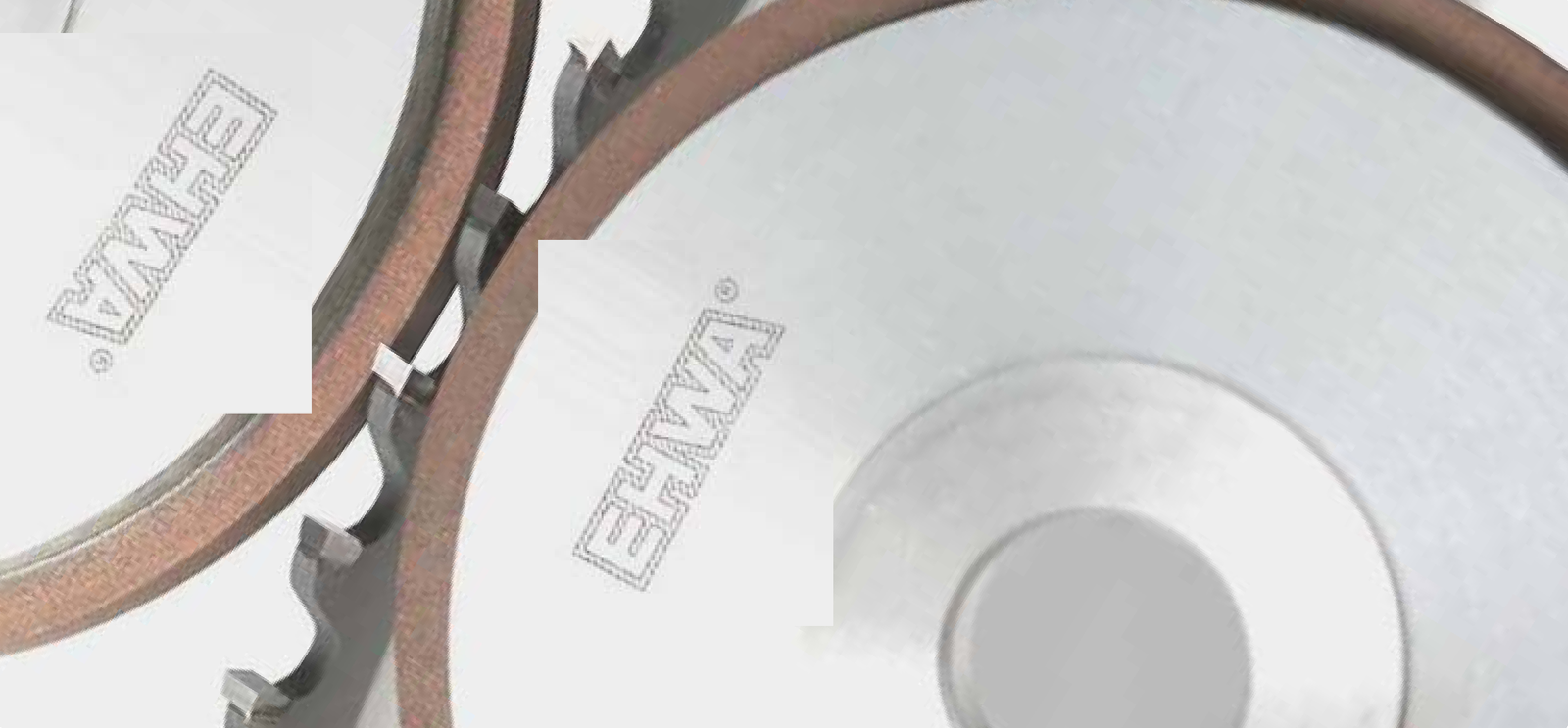
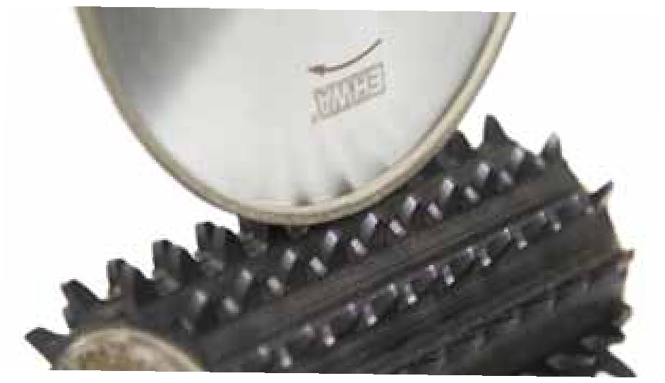
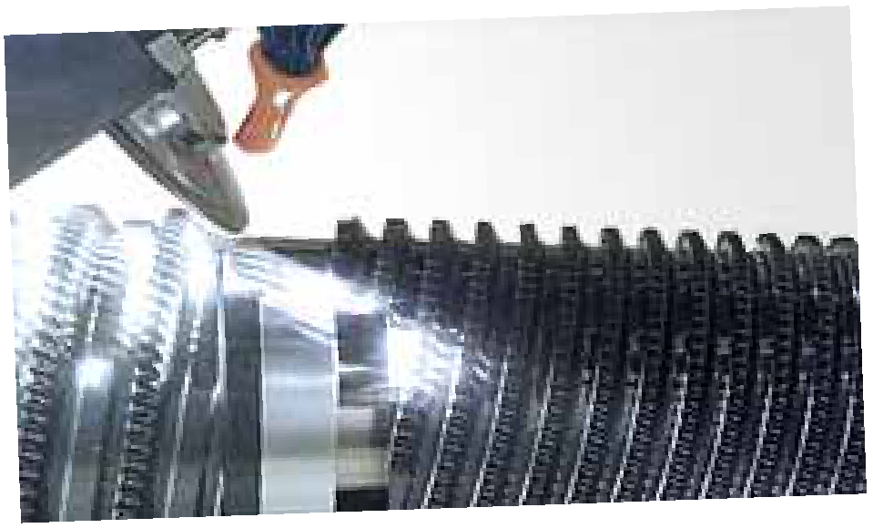
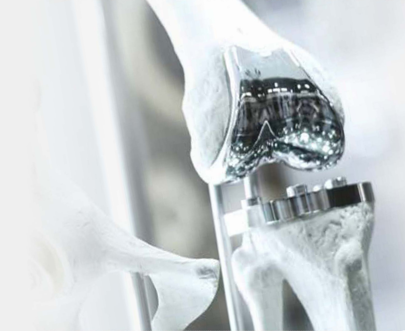
Superabrasive grinding tools support manufacture of precision medical components. The programme covers wheels and dressers for artificial-knee components, medical-wire grinding wheels and ECG tools for needles.
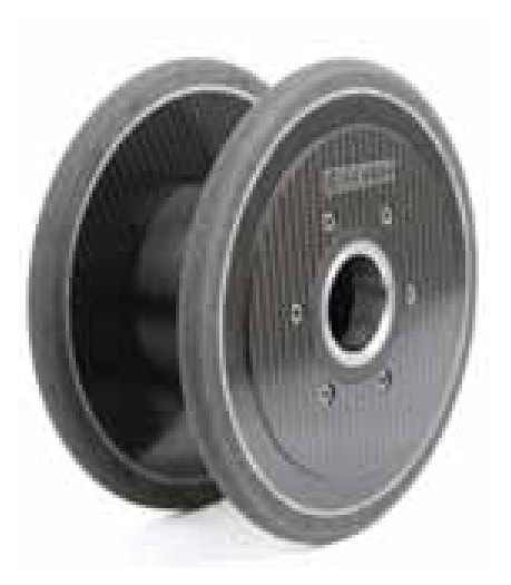
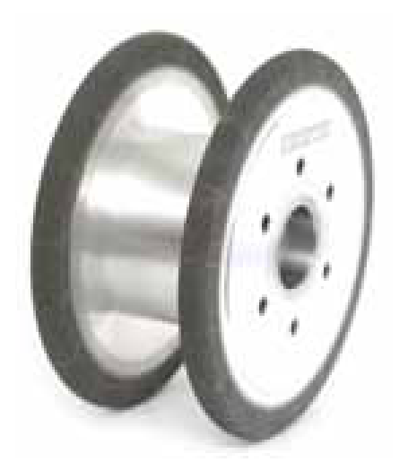
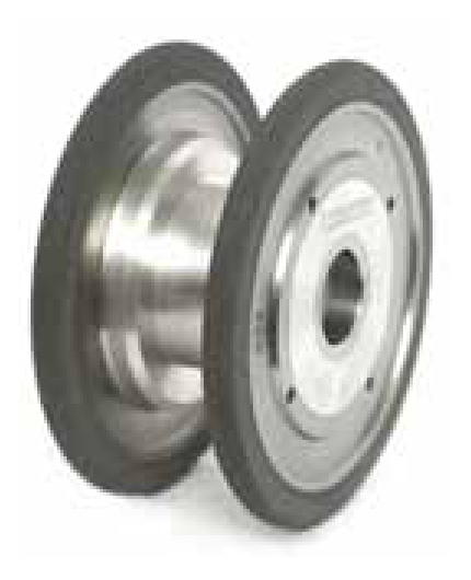
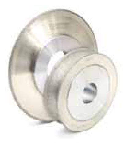
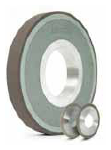
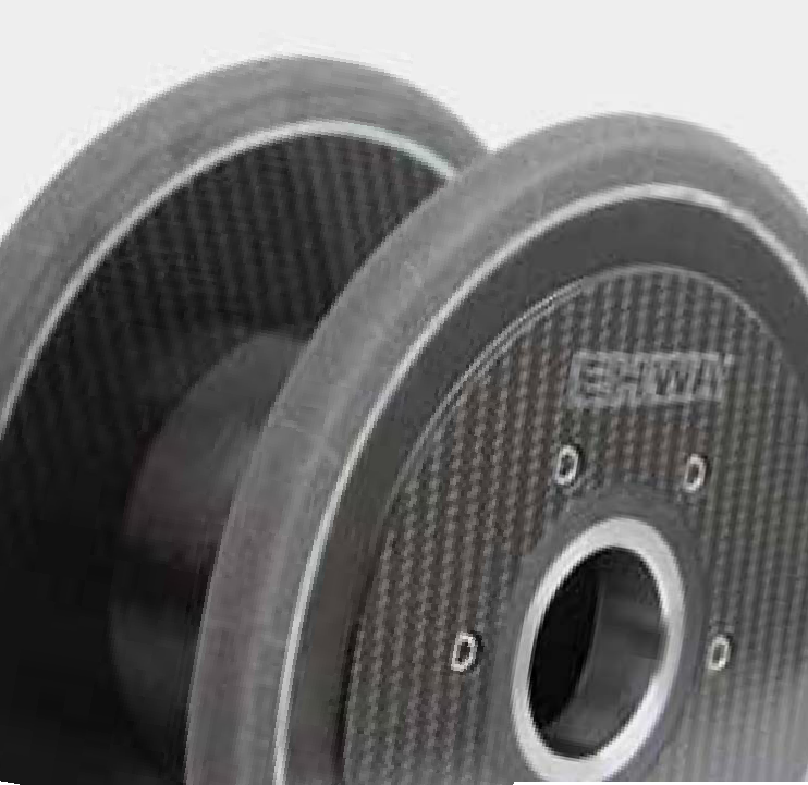
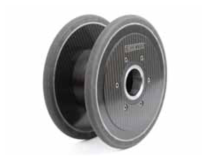
For artificial-knee components, designs include vitrified wheels with CFRP, aluminium-alloy or steel/aluminium bodies, and electroplated steel/aluminium designs. The following sections show tooling variants, specifications and machining benefits.



Grinding and dressing artificial-knee components
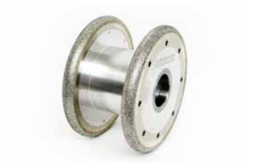
Tool forms are designed for grinding artificial-knee components. The described process features include high stock removal, good balance for high-speed operation, long dressing intervals and wheel life, and good grinding performance and surface quality. Profiled diamond dressers support grinding-wheel shaping.
The four body/bond variants are shown separately. Standard size and specification codes are listed in the table; the actual profile contour depends on the component being machined.
| Tool | Size designation | Specification |
|---|---|---|
| Vitrified CBN | VB-14F1, 250D-120T-20X-16U-8R-51H | B252L150VBW |
| Vitrified CBN | VB-14F1, 240D-120T-20X-18U-10R-51H | B252L150VBW |
| Diamond rotary dresser | ROTARY-RP 98D-25T-10R-25H | — |
| Diamond rotary dresser | ROTARY-IP1, 175D-2R-22T-52H | — |
| Electroplated CBN | EB-1FF1, 200D-120T-20U-12R-51H | B427 |
| Electroplated CBN | EB-1FF1, 200D-120T-12U-6R-51H | B252, B301 |
| Electroplated CBN | EB-1FF1, 160.45D-16T-8R-20H B427 | B427 |
Grinding wheels for medical wire
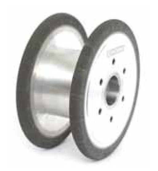
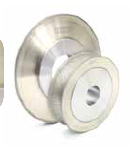
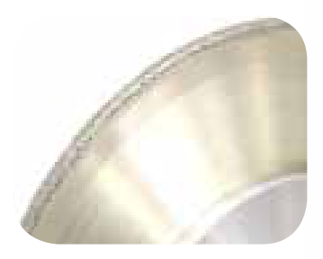
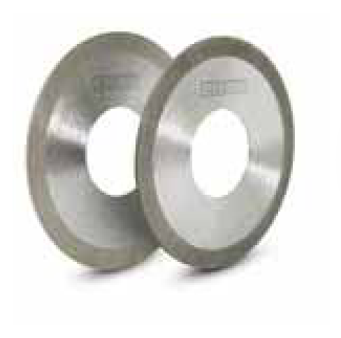
The first illustrated wheel design operates with low pressure and free cutting. Good wire surface quality, long wheel life and good balance support economical machining.
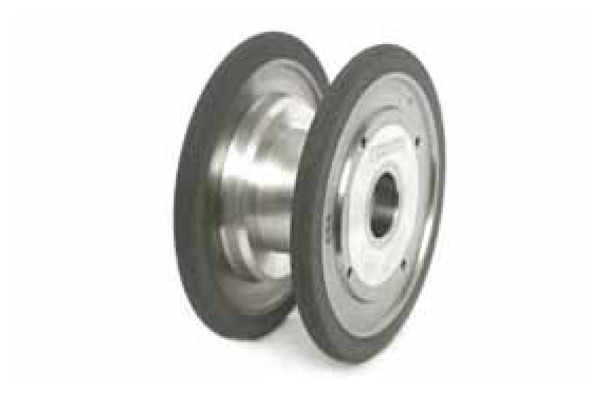
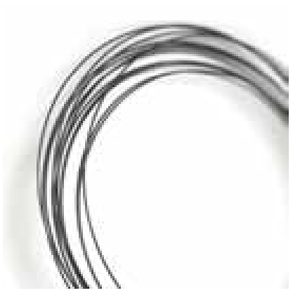
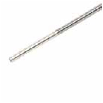
The second design provides a straight working face with a sharp edge. Low cutting force and a free-cutting layer support wire surface quality. The two workpiece images show coiled and straight wire.

Electrochemical grinding of medical needles
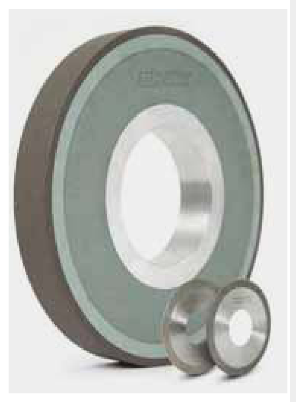
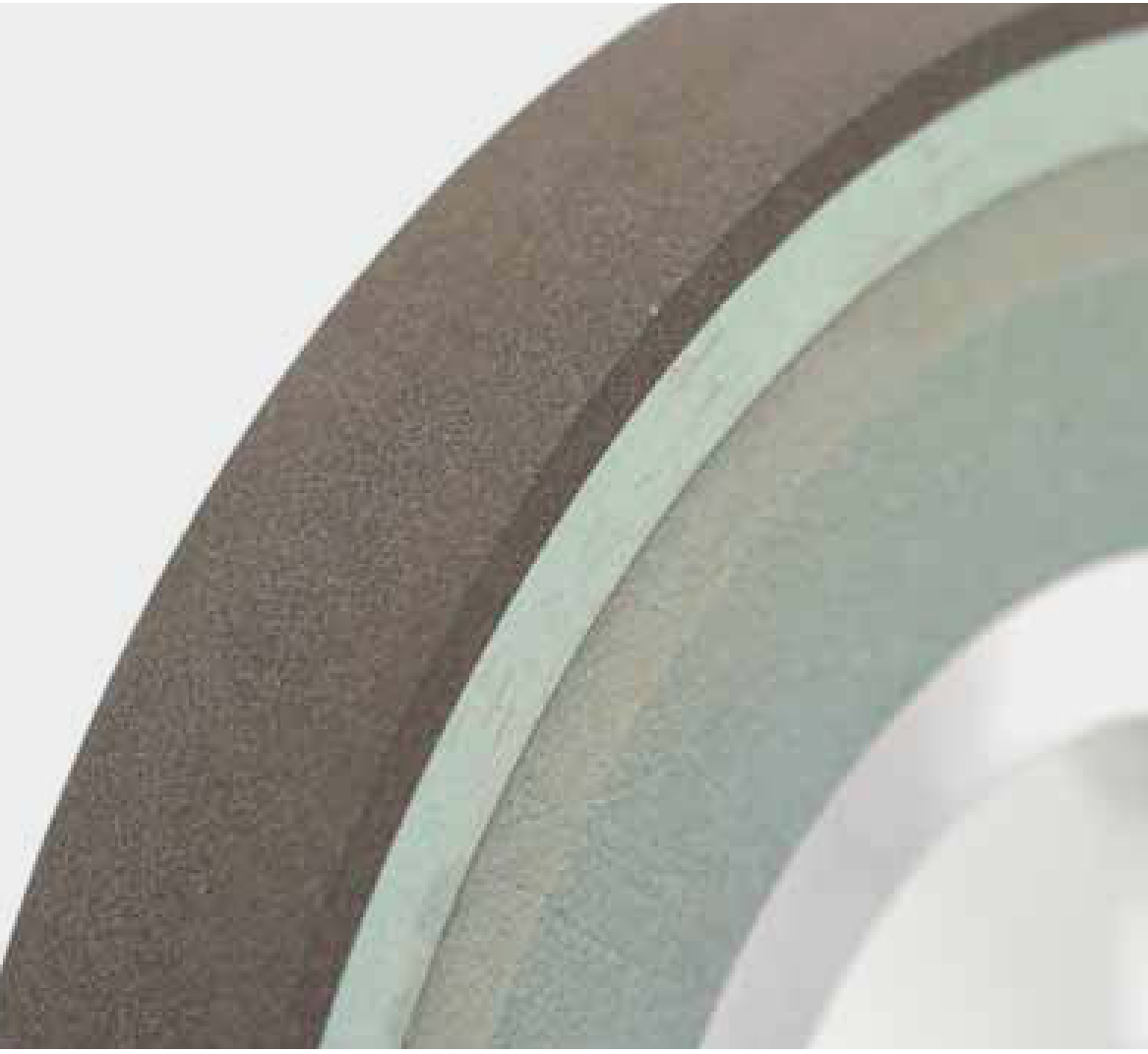
The metal-bond ECG wheels are intended for medical needles made from SUS/SUS304. ECG combines electrochemical removal with abrasive machining. The design supports low cost per part, high stock removal, consistent grinding performance and good, burr-free surfaces.
The comparison images show a needle surface with burrs after conventional machining and a burr-free example using the EHWA ECG wheel. The catalogue also uses the term “electrolytic polishing wheel”; the tooling and process are identified here as electrochemical grinding (ECG).
| Type | Specification |
|---|---|
| MB-1A1 | 204D-3T–15T |
| MB-3A1 | 204D-1U–2.9U |

Rotary dressers for turbine blades
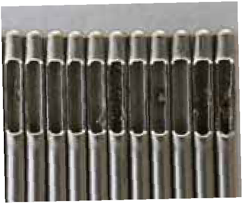
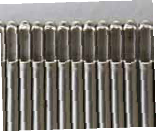
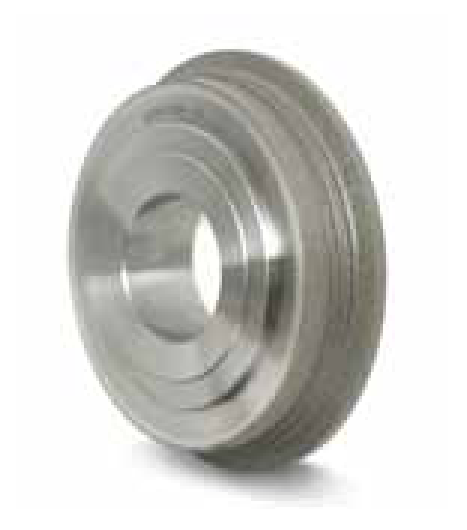
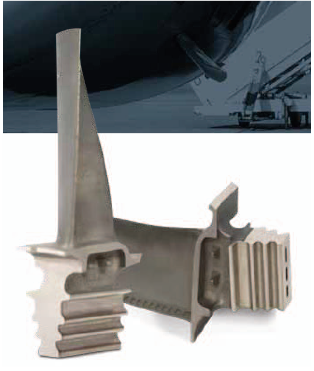
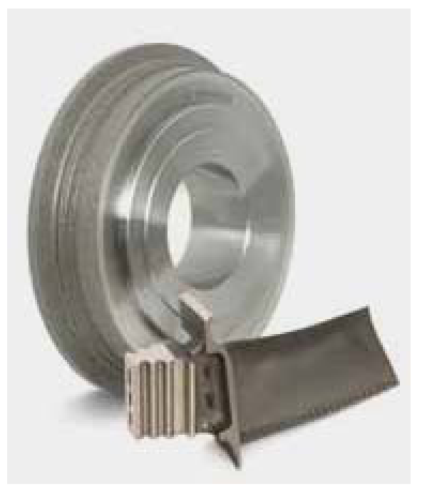
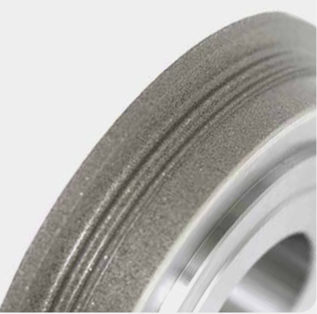
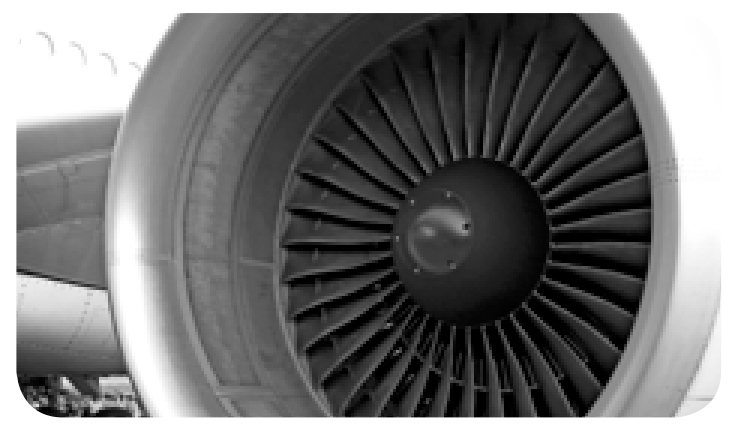
The dressers are intended for turbine blades in aircraft engines, power-generation turbines and marine turbines. Roll contours are designed for the workpiece. Long tool life and high tool precision support stable dressing performance in creep-feed grinding.
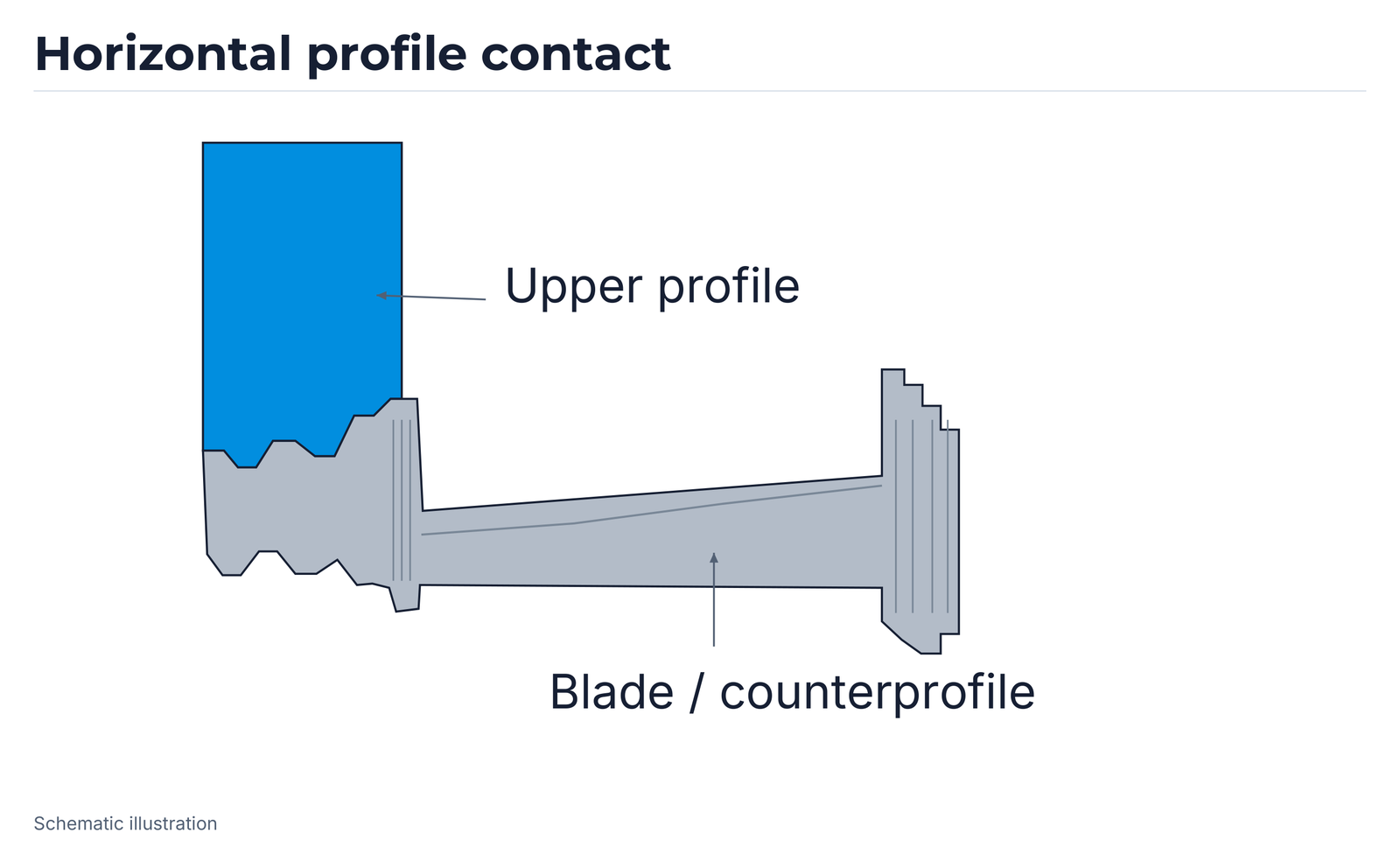
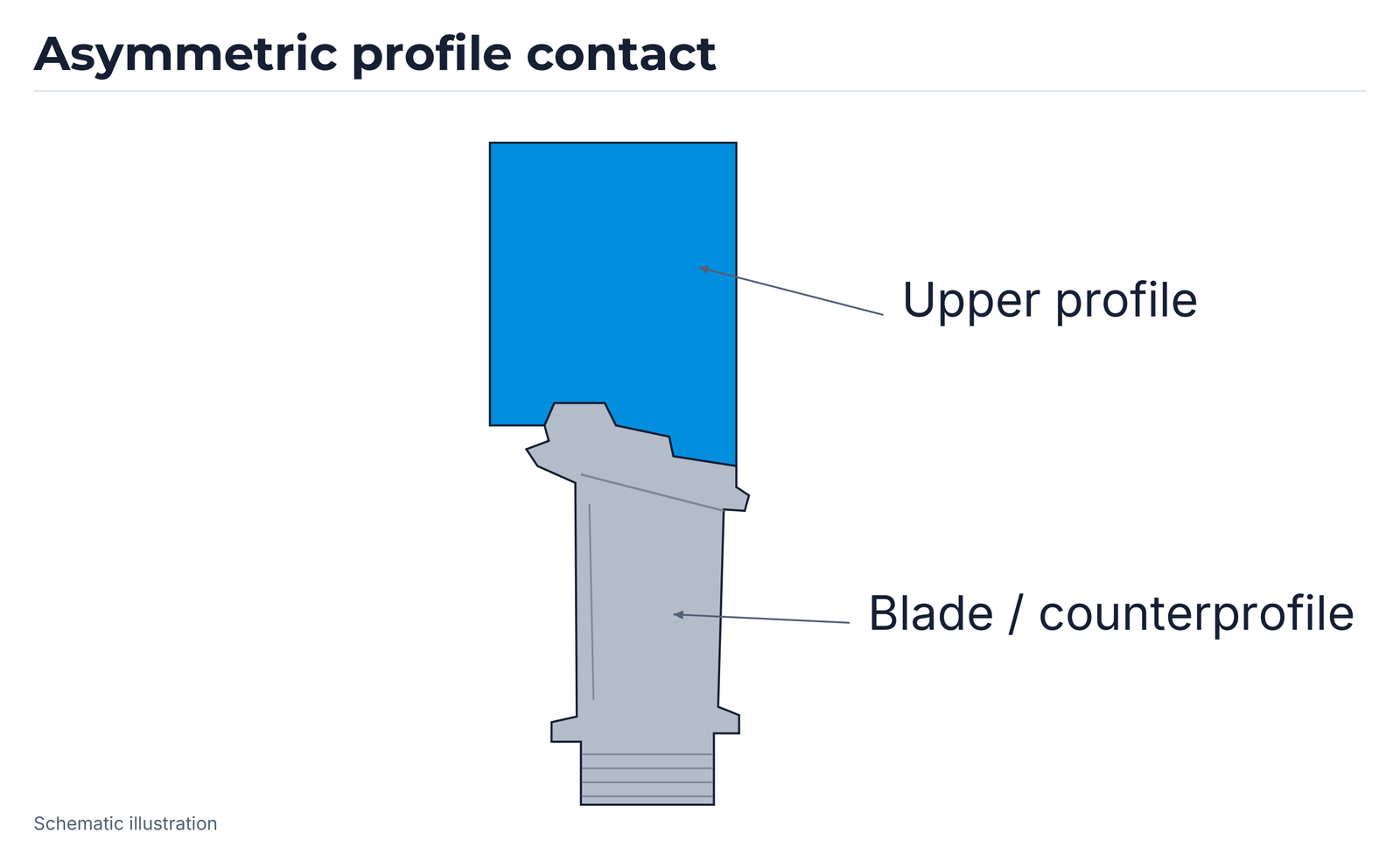
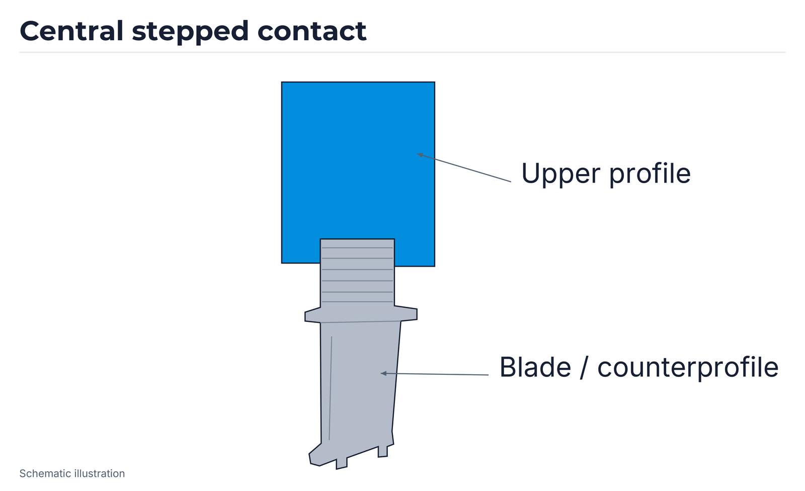
The four contact arrangements show different blade and counterprofile positions. They complement the tool and blade photographs with the corresponding form and contact geometry.


Stationary diamond dressers: materials and types
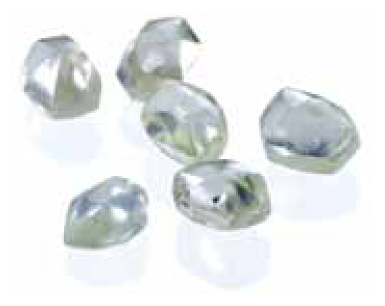
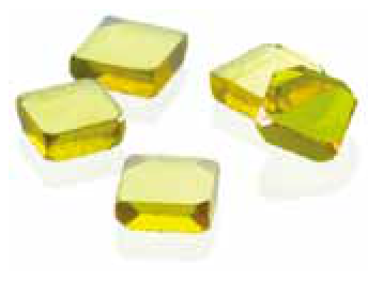
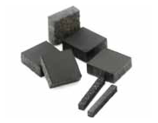
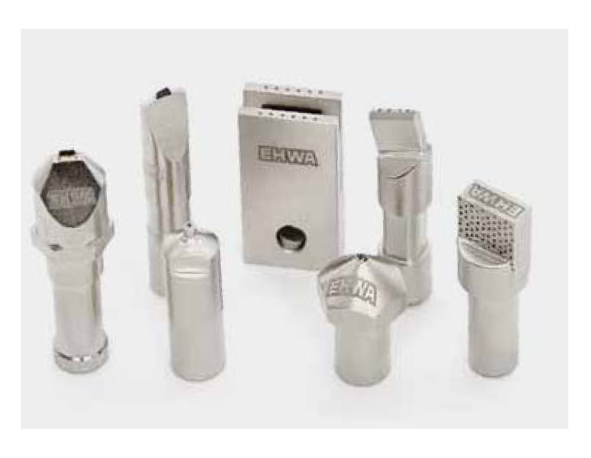
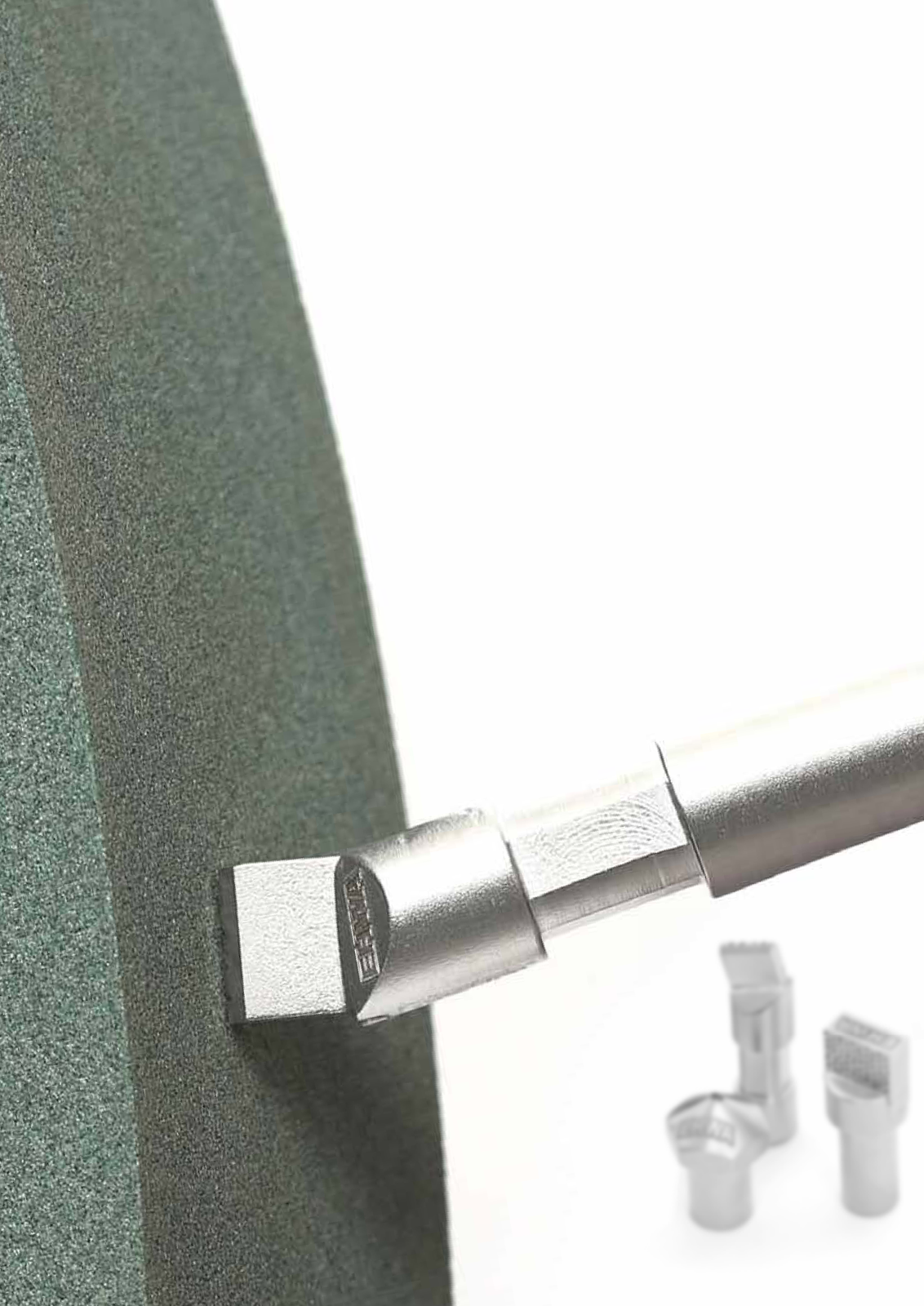
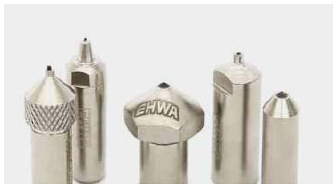
Stationary diamond dressers machine conventional abrasive wheels. Options include single-point, forming, multi-point and impregnated dressers. Natural, mono and CVD diamonds provide different starting forms for tool design. CVD stands for chemical vapour deposition.
Mono and CVD diamonds are presented as alternatives with comparable diamond properties for dressing. Suitability is assessed against the profile, cutting-point arrangement and loading; this does not imply identical life for all diamond materials.
| Diamond material | Mapped dresser types |
|---|---|
| Natural diamond | SDD, FDD, MDD, IDD |
| Mono diamond | SDD, FDD, MDD |
| CVD diamond | SDD, FDD, MDD |

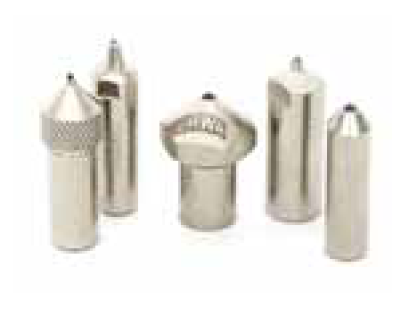
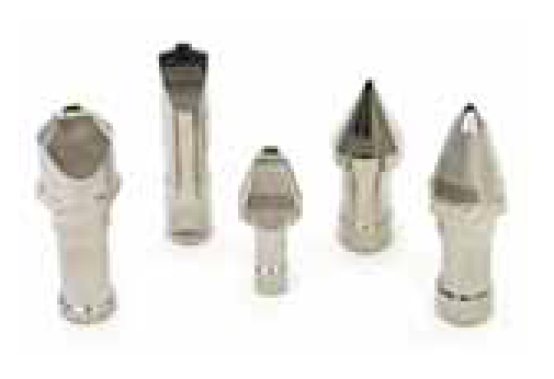
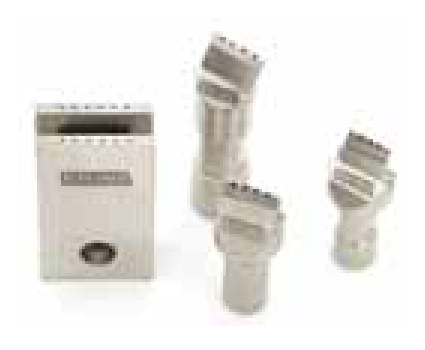

Selecting dressers by wheel shape and profile
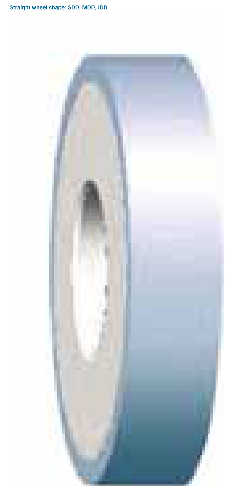
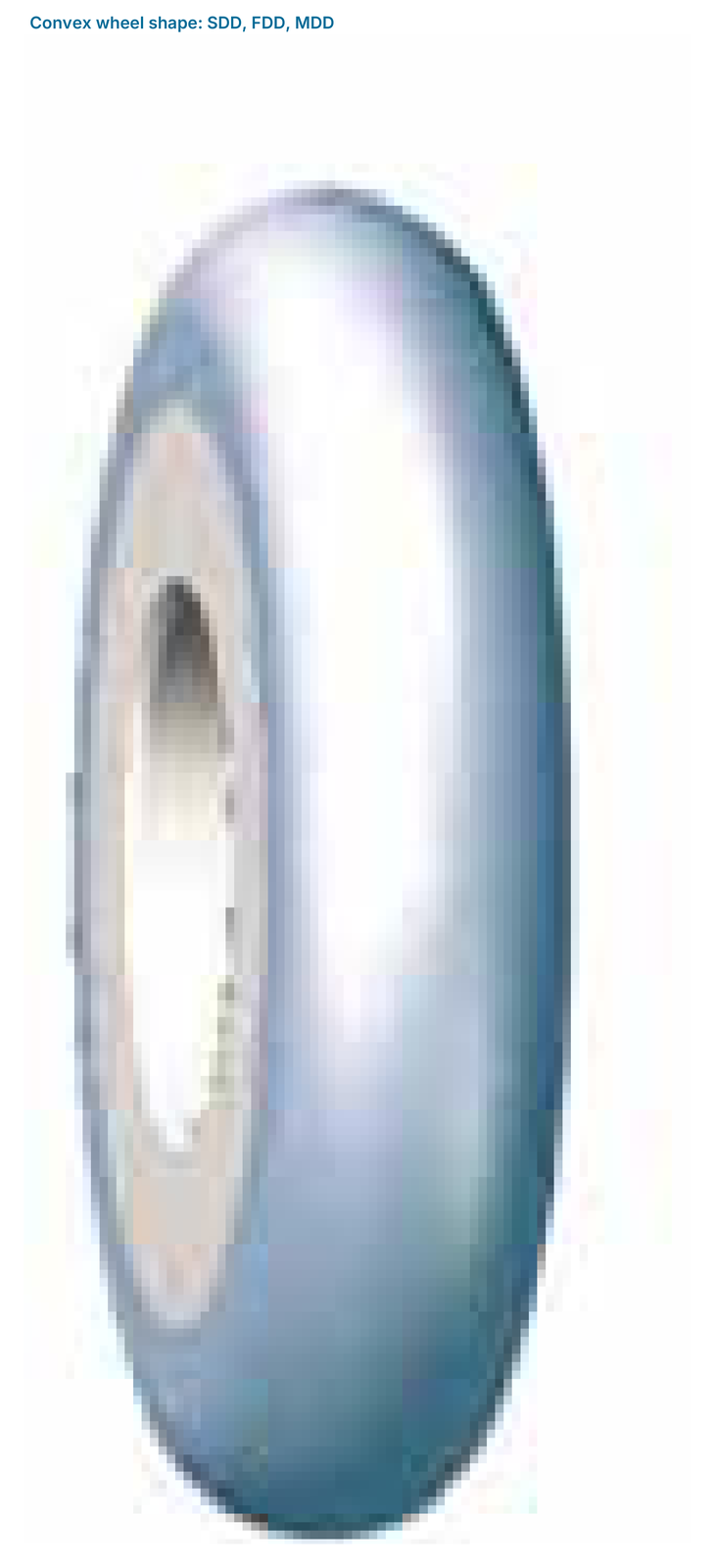
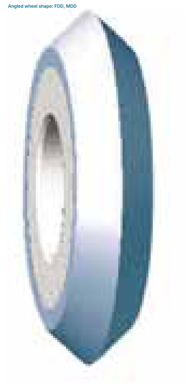
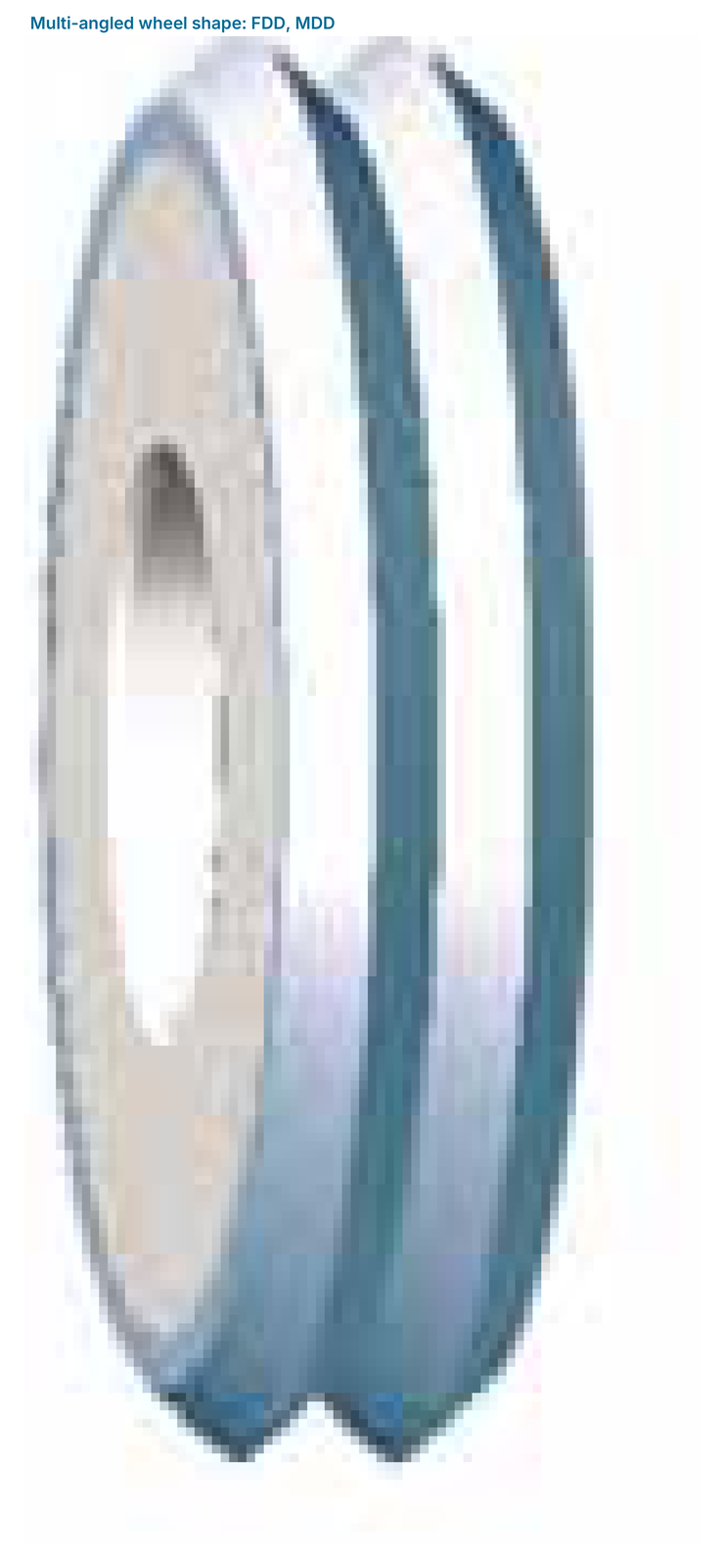
Wheel shape determines the suitable dresser type. The six illustrations distinguish straight, tapered, convex, concave, angled and multi-angled wheels. The selection table adds the tasks and size designations of the four dresser groups.
Single-point dressers are classified by carat size; forming dressers distinguish angle and radius forms. Multi-point dressers are selected by the number and arrangement of diamond rods. Impregnated dressers are intended for large, wide wheels, surface grinding and centreless grinding.
| Wheel shape | Dresser |
|---|---|
| Straight | SDD, MDD, IDD |
| Tapered | SDD, MDD, IDD |
| Convex | SDD, FDD, MDD |
| Concave | SDD, MDD, IDD |
| Angled | FDD, MDD |
| Multi-angled | FDD, MDD |
| Type | Applications | Selection feature |
|---|---|---|
| SDD | Straight and simple profiles; thread and gear grinding | Carat range 1/30–1.5 CT |
| FDD | Simple and complex profiles; thread and gear grinding | Angle/radius form: roof, chisel, cone |
| MDD | Straight shapes and accurate complex profiles; particularly angular profiles | Diamond rods: 2–10 |
| IDD | Large and wide wheels; surface and centreless grinding | Grit #18–#140 |


Bonds for superabrasive grinding tools
The bond holds the abrasive grains and influences cutting behaviour, profile stability, coolant access and tool life. The following product sections describe bond families and their applications separately.
Product families and bond systems
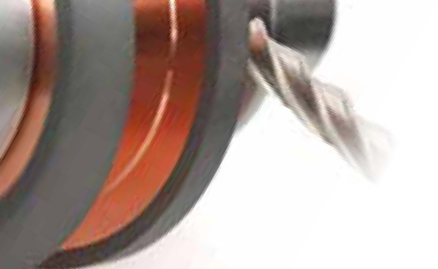
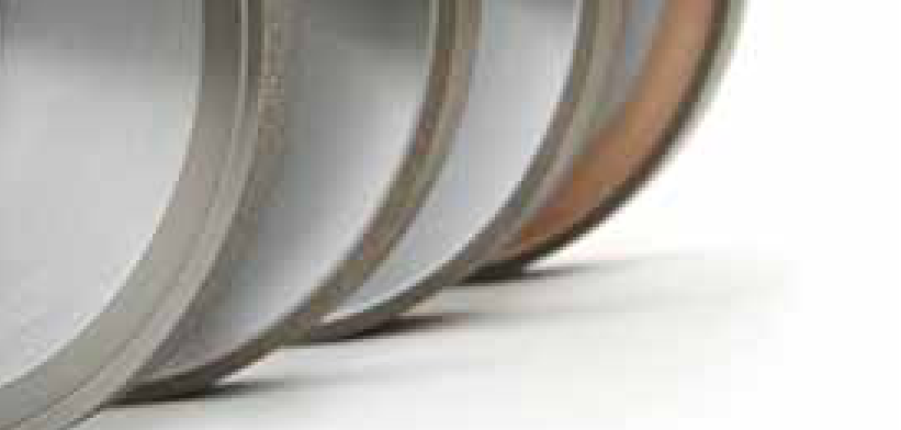
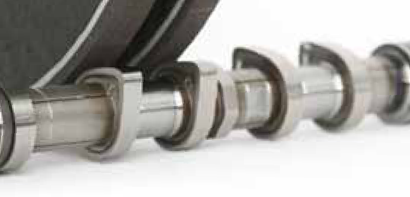
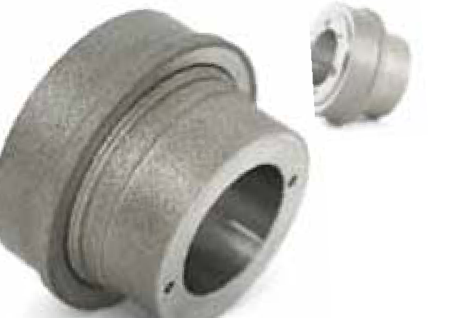
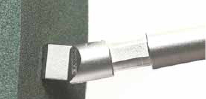
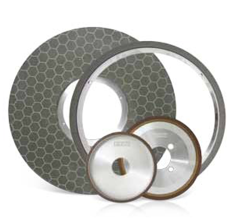
The six product groups combine different bond systems and dressing methods. Resin, metal, vitrified and electroplated bonds are selected according to tool material, contour and operating conditions. Rotary and stationary diamond dressers complement the grinding wheels for controlled shaping and restoring cutting ability.

Resin-bond diamond and CBN grinding wheels
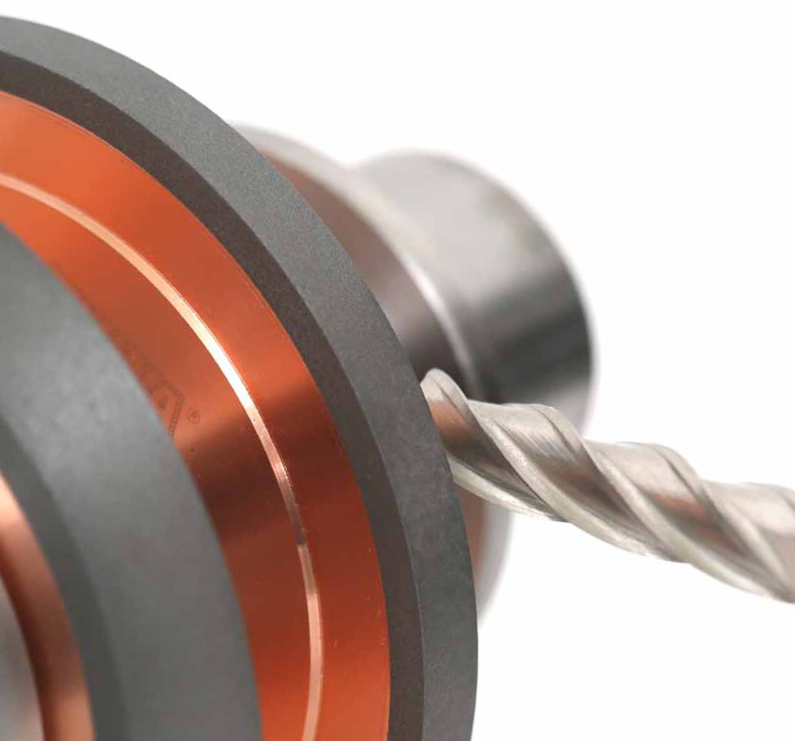
Increasing use of difficult-to-grind materials and alloys in automotive and machinery industries drove development of diamond and CBN tools. Resin-bond wheels combine these abrasives with inorganic fillers and resins such as phenolic resin or polyimide; curing forms the bond.
Applications include surface, external cylindrical, internal cylindrical and centreless grinding, grooving and creep-feed grinding. Depending on abrasive and specification, materials include superalloys, cermet, ceramics, glass, ferrite, high-speed steel and other tooling materials.
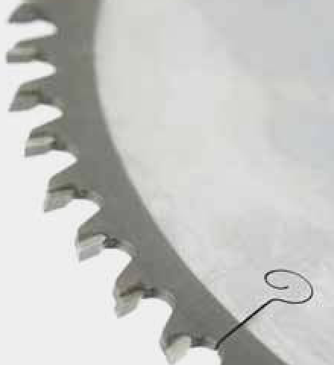
Diamond designs support fast cutting with favourable thermal behaviour on carbide-tipped saws, cutters and reamers. Further tasks include precision grinding of carbide dies, rolls and wear parts, ceramic finishing, and machining of tungsten-carbide and ceramic thermal-spray coatings. CBN designs are intended for high-speed, tool and die steels and the catalogue materials with hardness above HRC 50; the mapping depends on material and heat treatment.
EHWA has been developing the programme through research and manufacturing experience since 1975. It includes cylindrical, creep-feed, saw and insert grinding wheels for series production with consistent surface finish. Wet or dry operation is designed for the specification. The service offering includes application-appropriate quality, economical tooling selection, coordinated delivery times and support.
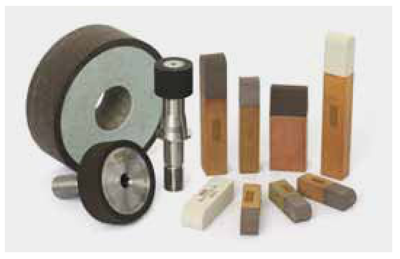
Metal-bond diamond grinding tools
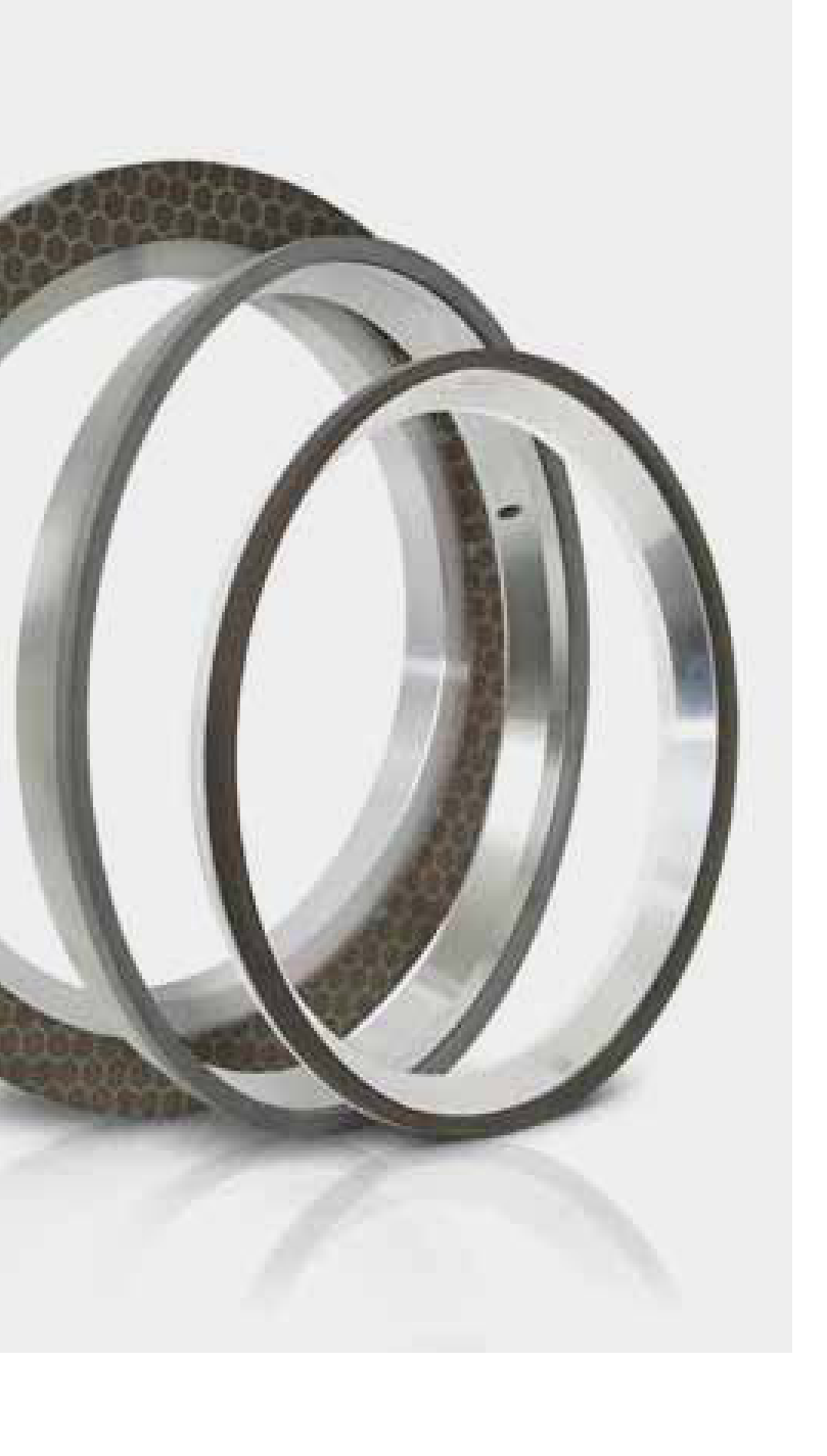
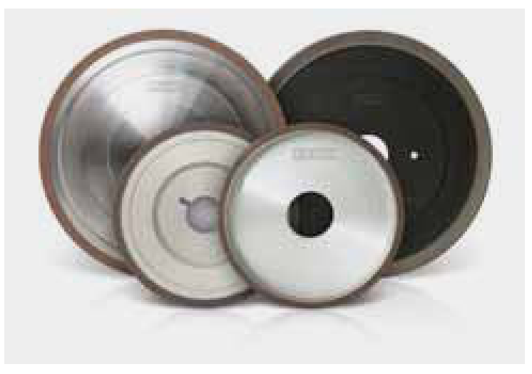
Glass products combine optical function, design and diverse shapes. Metal-bond diamond tools enable grinding and shaping of these hard, brittle materials, including automotive glass, architectural glass and spectacle lenses.
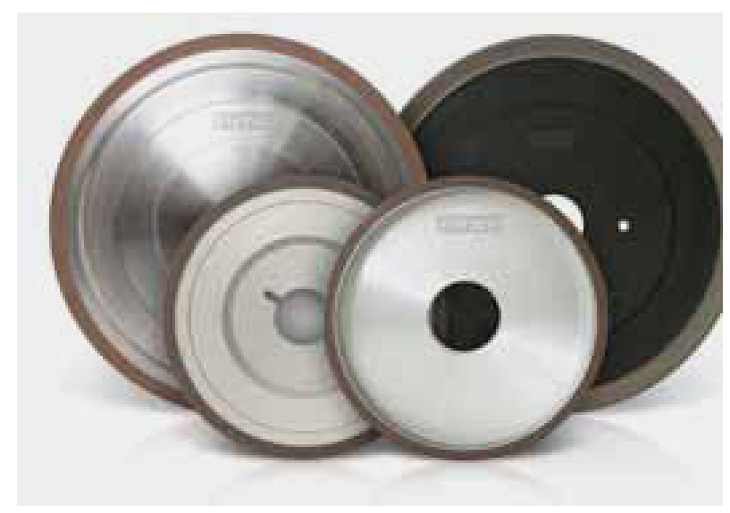
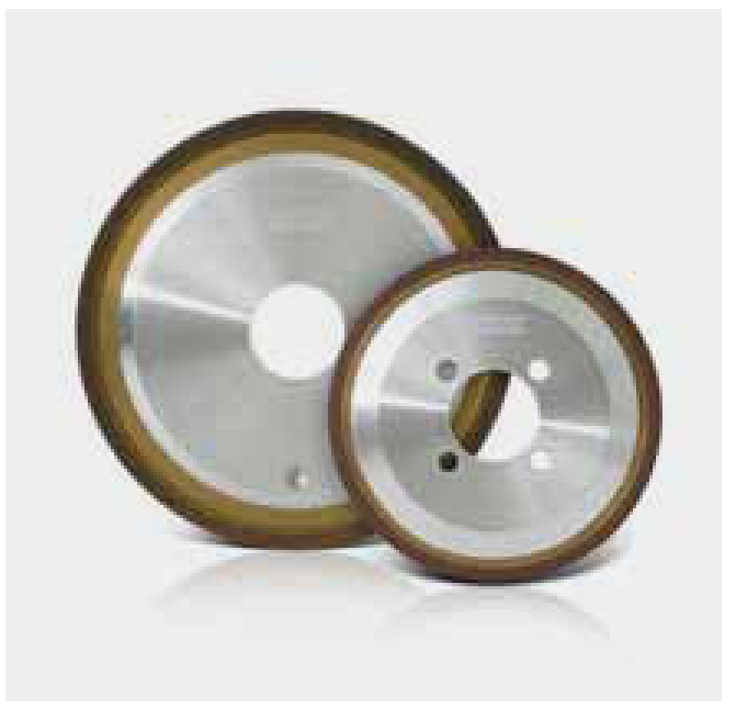
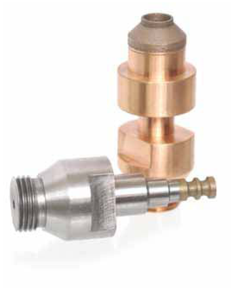
Further applications include grinding and sharpening carbide-tipped saws and machining ferrite, ceramics, tungsten carbide, automotive parts, quartz and stone. The images show automotive edge grinding tools, lens tools, honing stones and mounted tools.
In the development history documented by the catalogue, EHWA manufactured edge wheels for automotive glass and 14–33 inch cathode-ray tubes from the late 1970s. The programme expanded to display glass in the early 1990s, followed by electrolytically assisted grinding tools. Continued metal-bond tool development addresses the requirements of different customer applications.

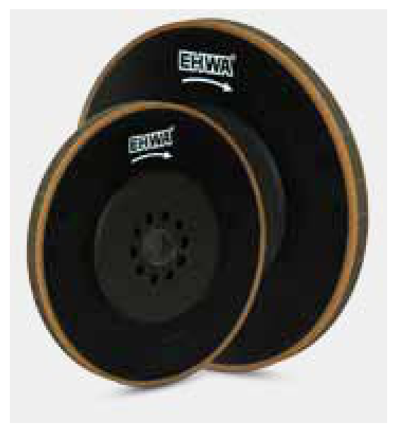
Vitrified diamond and CBN grinding wheels
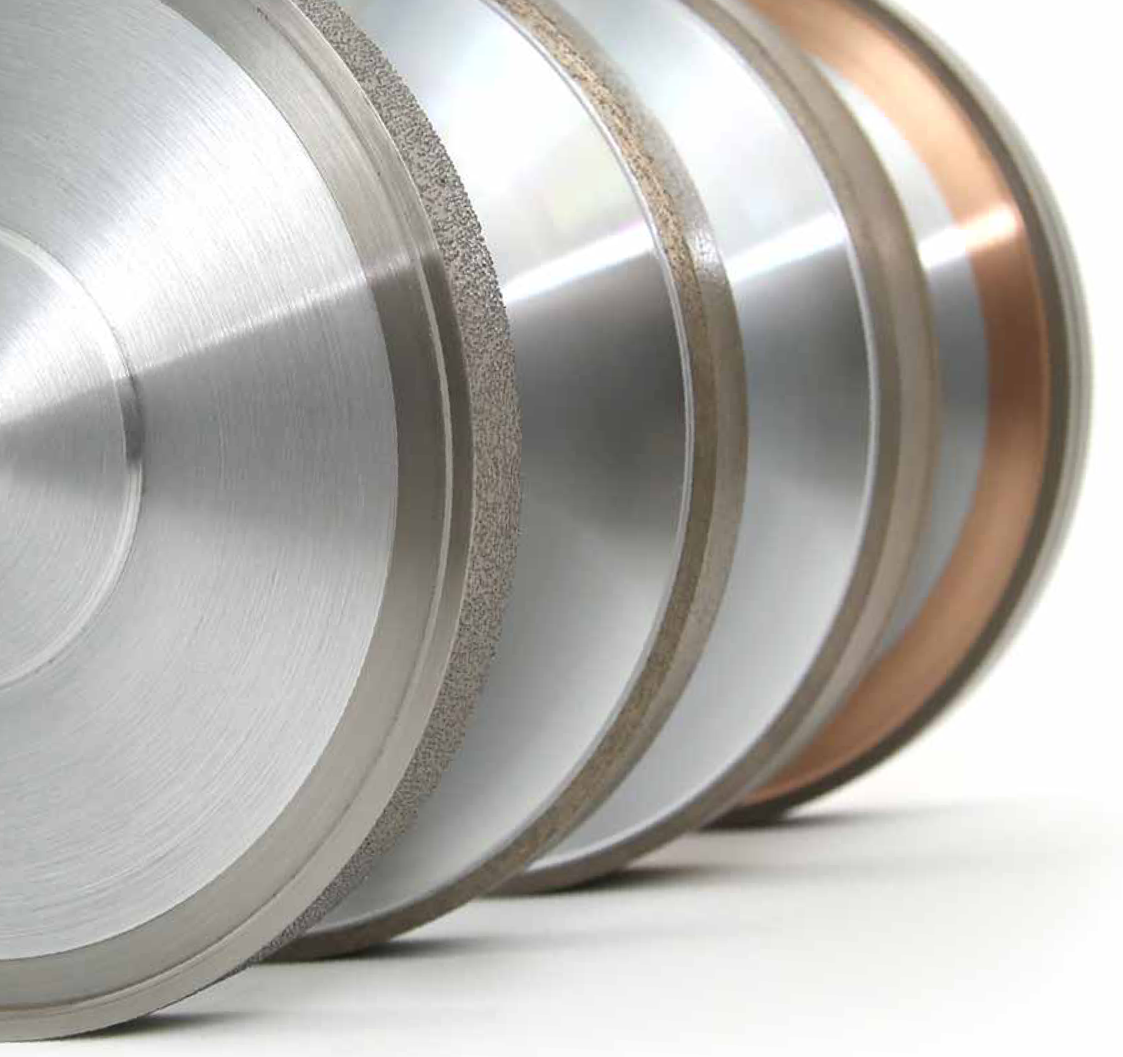
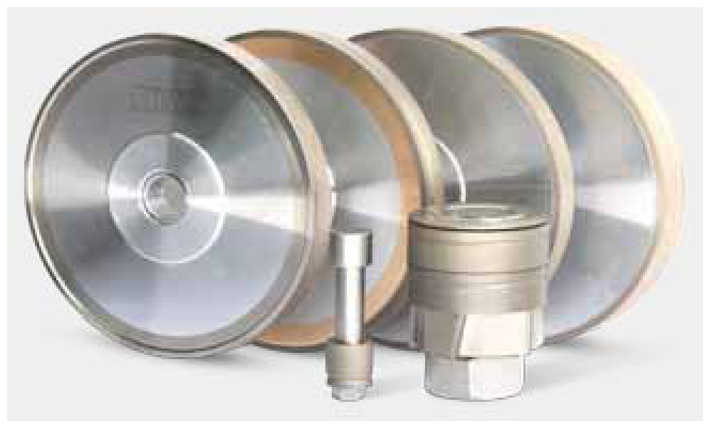
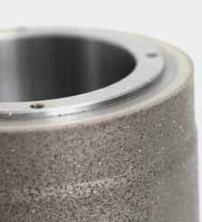
Automated grinding processes need durable, form-stable tools with reliable cutting behaviour. Vitrified bonds provide an adaptable system of grain retention, pore structure and dressability. Free cutting, long tool life and high productivity can reduce process intervention. Self-sharpening behaviour complements controlled dressing; runout and profile are still established for the application.
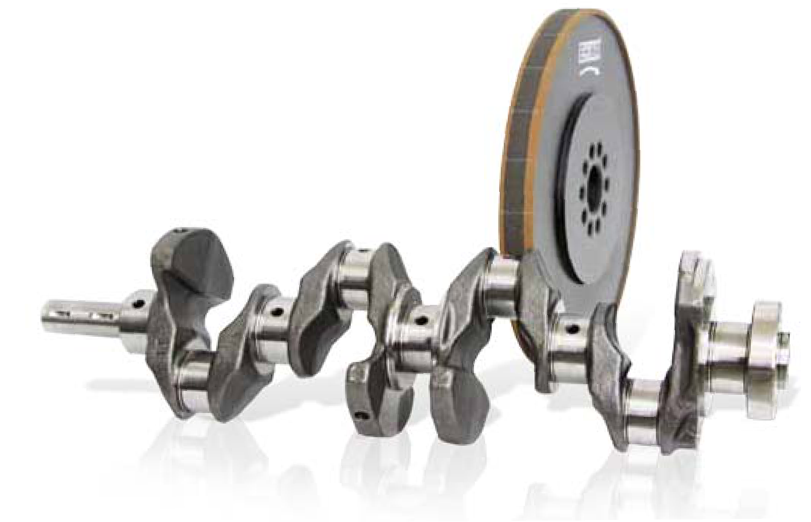
From the late 1980s, EHWA developed vitrified CBN wheels for automotive components such as constant-velocity joints. The programme expanded to precision machine parts, bearings, gears, tools and dies, semiconductors, ceramics and cermet, particularly PCD/PCBN cutting tools.
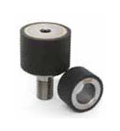
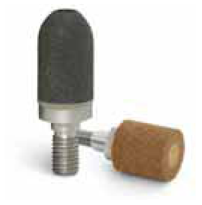
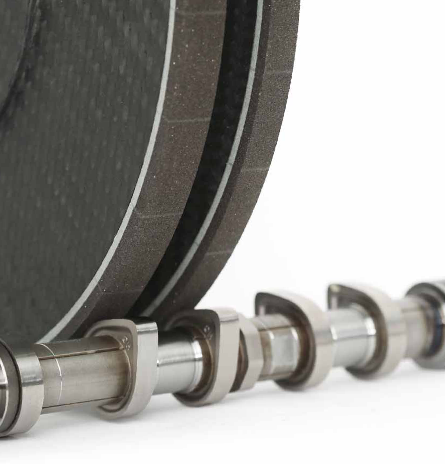
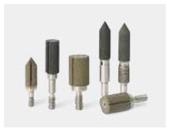
The images show peripheral wheels for PCD/PCBN inserts, injection-nozzle bore grinding tools, bearing tools and honing stones, and crankshaft wheels. Continued development addresses process performance and the requirements of these applications.

Electroplated diamond and CBN tools
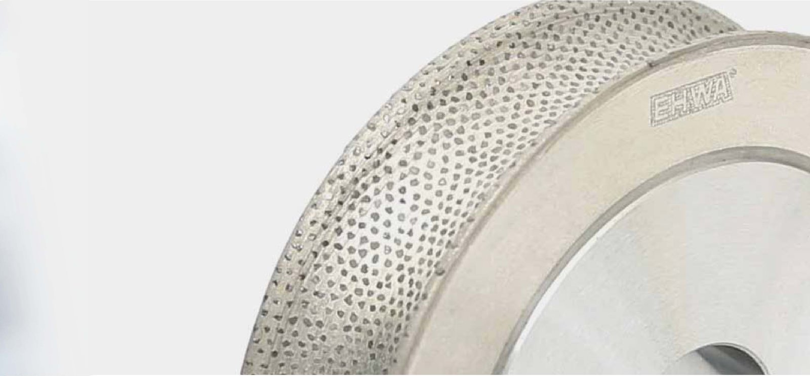
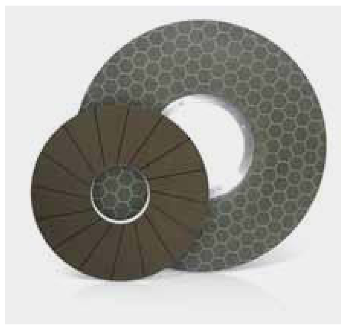
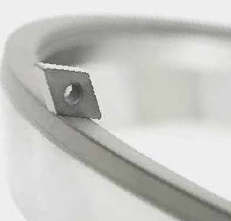
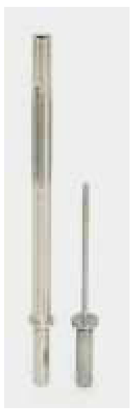
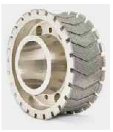
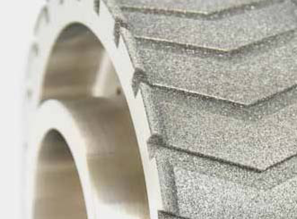
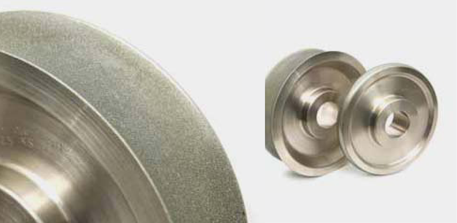
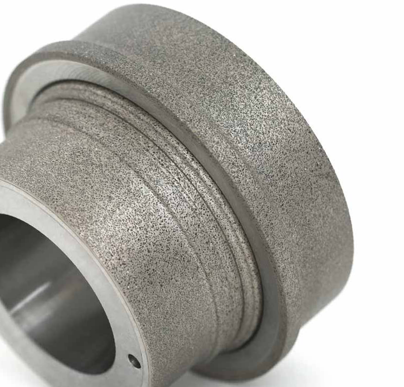
In electroplated tools, a nickel matrix retains diamond or CBN grains on the body. The catalogue describes single- or multilayer constructions depending on the application. The process allows different forms and contours. High grain protrusion and dense surface grain coverage support free cutting, high stock removal and efficient grinding.
Material groups include non-ferrous metals, hardened steels, fibre-reinforced plastics, ceramics and composites; diamond or CBN is selected for the material. EHWA has developed and manufactured electroplated tools since 1992. Alongside conventional nickel-plated designs, the programme includes reverse-plated diamond rotary dressers for automotive and aerospace applications and nickel-bond wafer dicing blades for semiconductors.
Illustrated designs include reamers, brake-pad wheels, ferrite grinding wheels and tools for SiC moulds. The programme continues to develop for individual customer applications.



Diamond rotary dressers: precision for series production
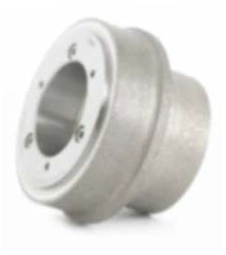
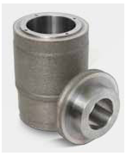
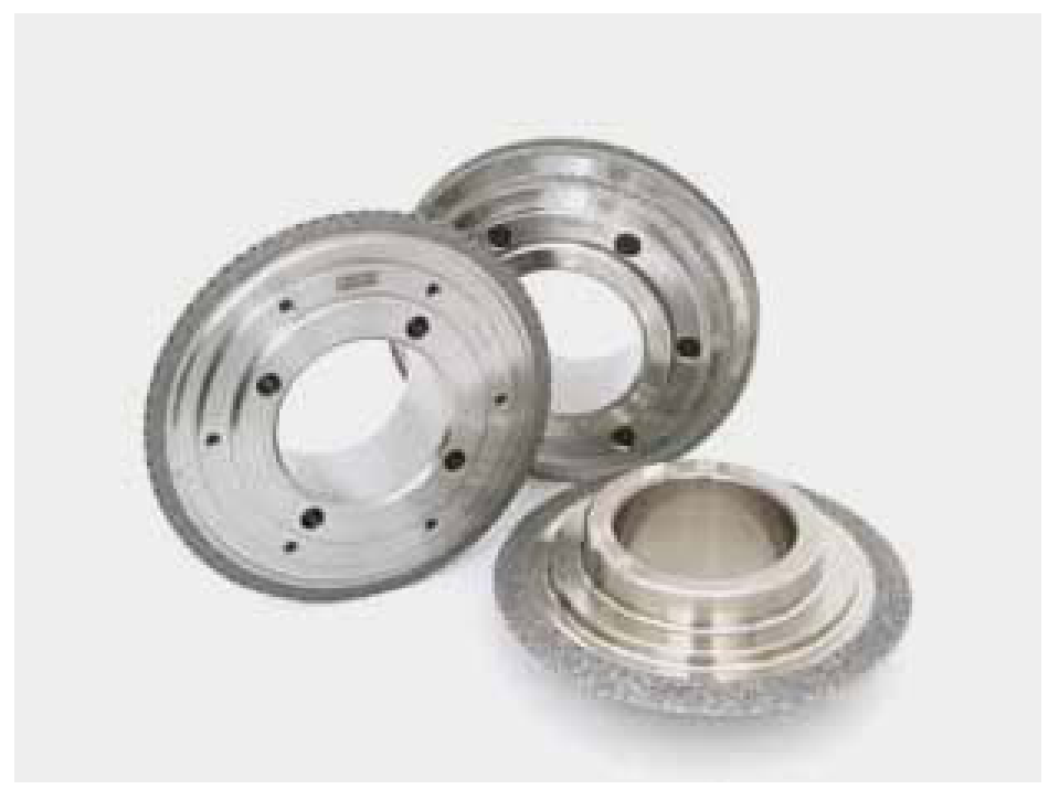
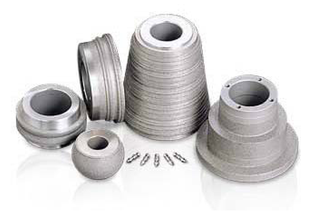
Diamond rotary dressers support economical series manufacture of high-precision parts, including engine and turbine components for automotive and aerospace applications. They form the required contours in the grinding wheel quickly and accurately.
According to the catalogue history, EHWA invested in rotary-dresser development, manufacture and specialist personnel from 1990. Supply to automotive and aerospace applications began in 1992. Dressers profile aluminium-oxide and silicon-carbide wheels and other application-matched grinding systems. Profile tasks include bearings, screw and thread forms, and gears.
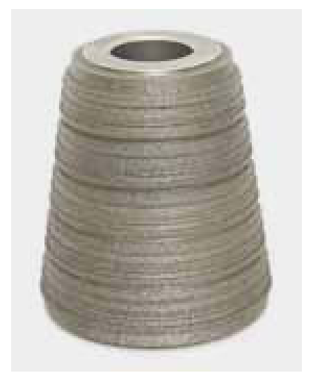
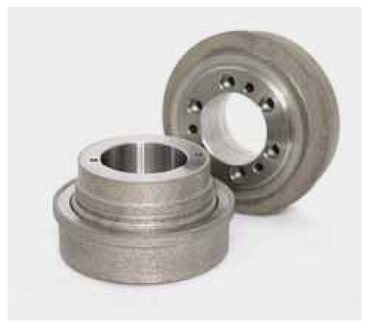
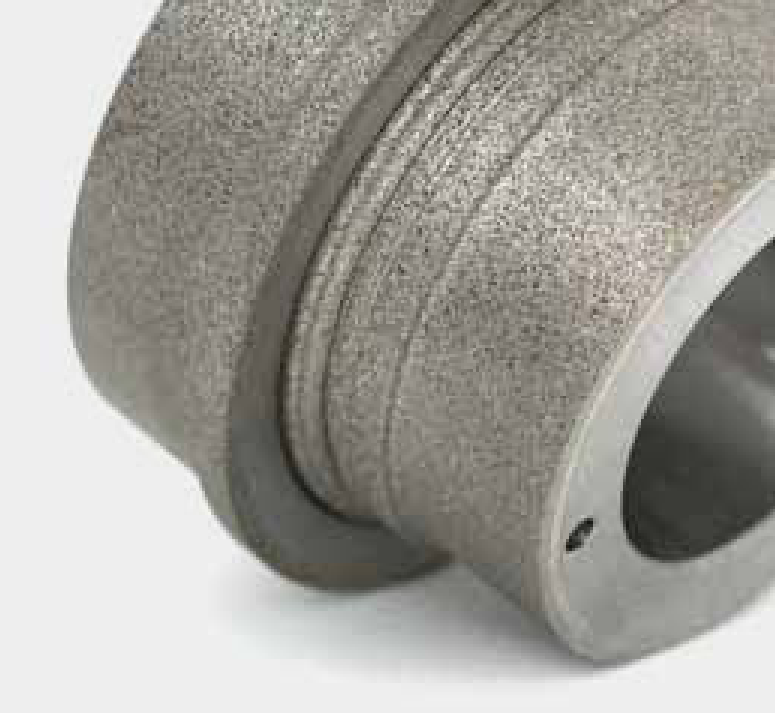
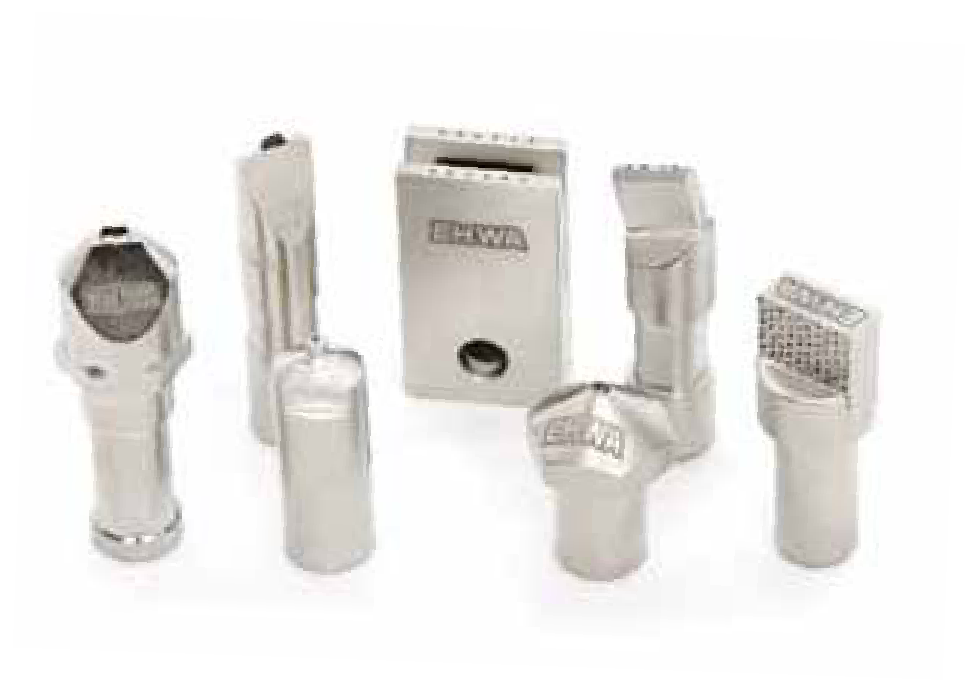
The illustrations show dressers for water-pump and ball bearings, gears, injection needles and turbocharger components. Tool precision, repeatable profile form and appropriate contour design underpin selection.
Stationary dressers: truing and restoring cutting ability
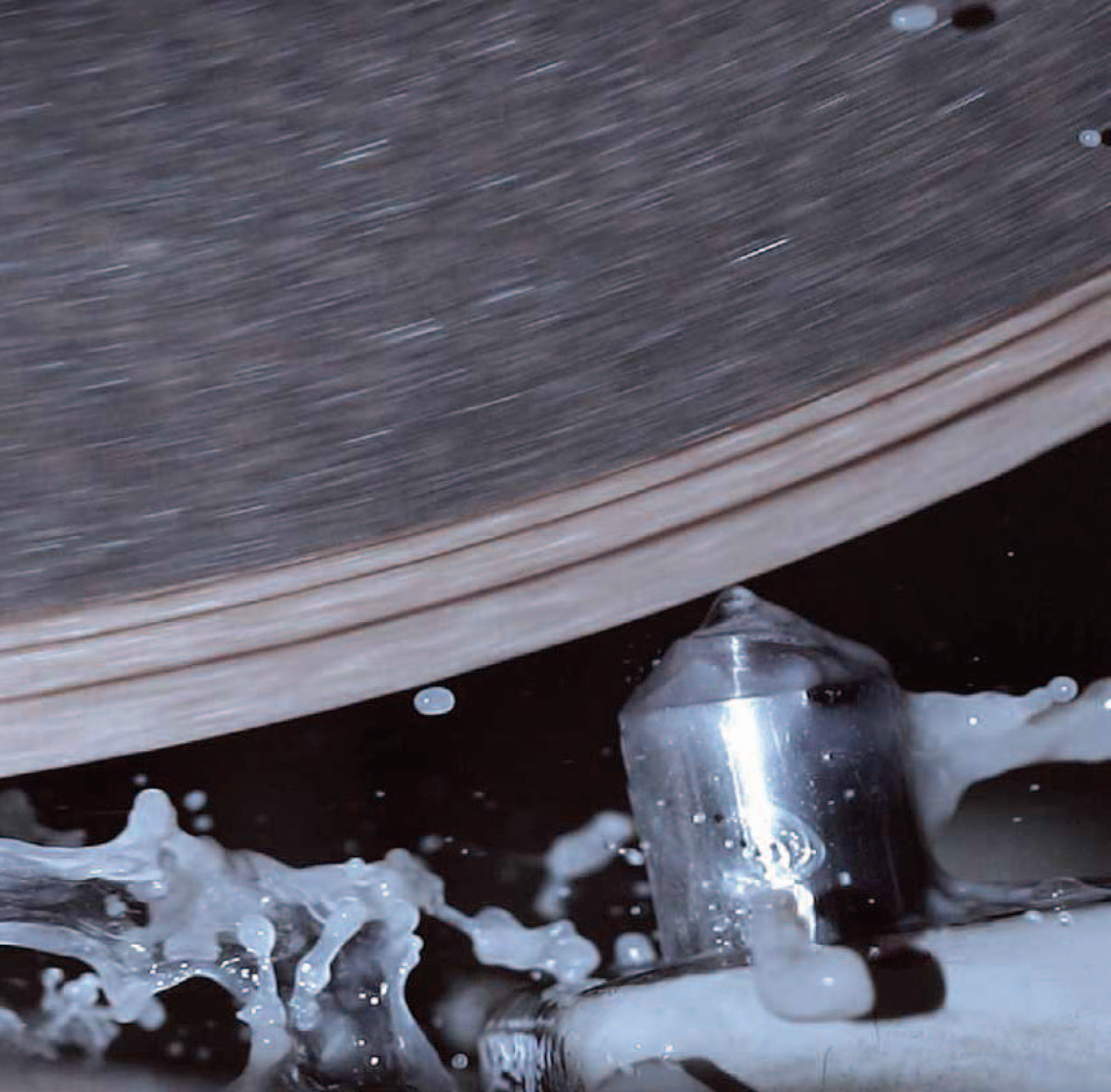
Truing establishes the form and runout of the mounted grinding wheel. Dressing opens the grinding surface and restores grain exposure and cutting ability. It removes adhering residues such as braze and steel particles and small amounts of bond. It is required when the wheel becomes loaded or glazed and, depending on the process, after form or runout correction. The catalogue recommends wet truing.
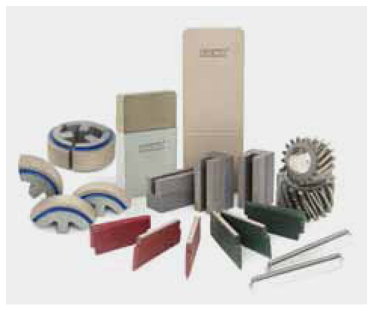
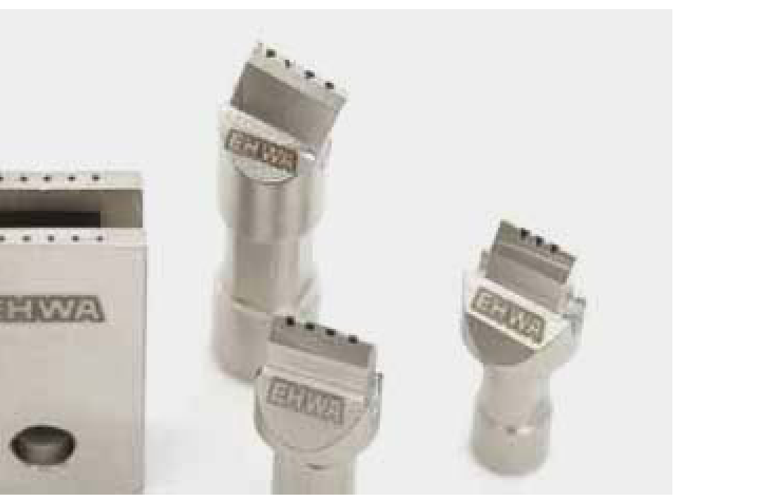
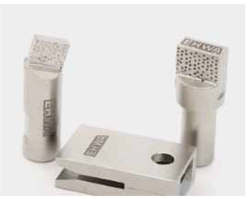
SDD are produced by sintering a selected diamond in a metal matrix within a steel shank, with its point concentric to the shank. MDD contain two or more diamonds in a metal matrix. Their distributed cutting points suit larger and wider wheels. They distribute loading, can reduce frictional heat and premature failure, and support long life and faster dressing.
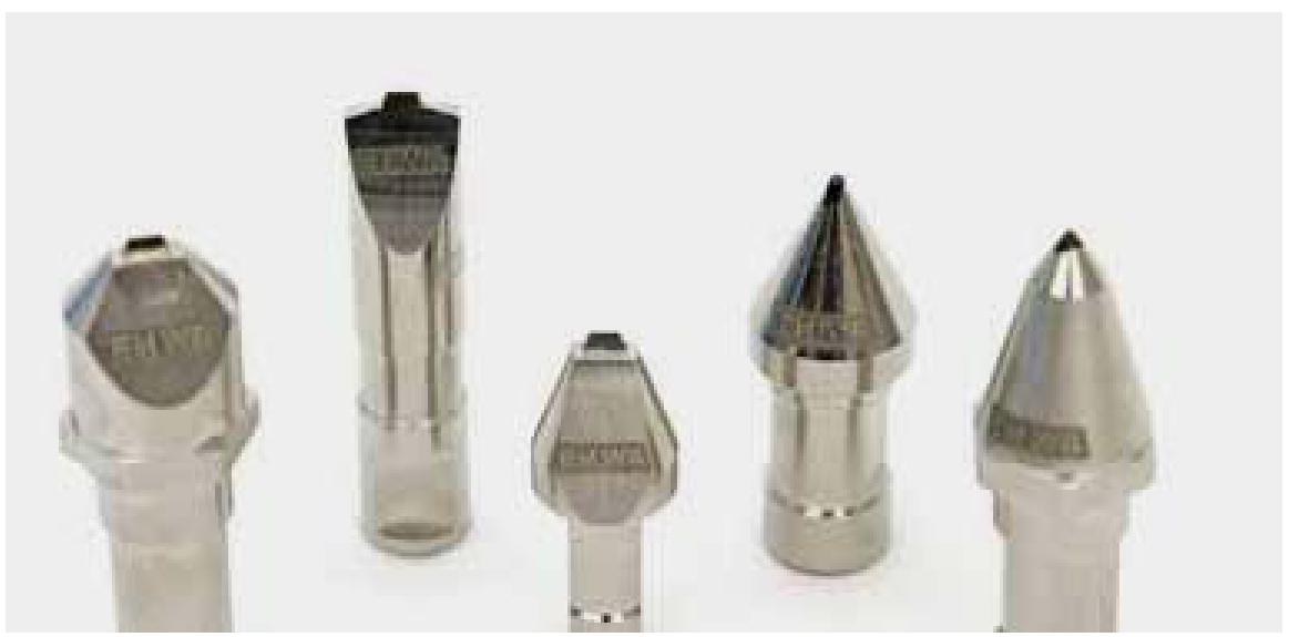
FDD use high-quality mono diamond sintered in a metal matrix in a steel shank, then ground to the required form, such as a conical point with radius, facet or profile. IDD are produced by sintering selected diamond particles with a metal matrix. They support economical dressing and long tool life on large and wide wheels. Continued development of all four types addresses customer requirements.
Technical specification: from abrasive to tool form
The following selection guides cover abrasive, grit, concentration, bond and tool form. Product codes and dimensional designations remain the basis for the specific design.
Technical selection and ordering information
Technical selection combines abrasive, grit, grade, concentration, bond and tool geometry. The following sections explain EHWA markings for resin, vitrified and metal bonds, abrasive types, bond modifications, wheel shapes and key dimensions. Reference charts and general guidance for diamond and CBN wheels follow.

Information for enquiries and orders
Accurate shape and dimension information supports tool design. Please include a drawing where possible. The following eleven items bring together tool selection and process data.
| No. | Information | Required details |
|---|---|---|
| 1 | Shape | Tool or wheel form |
| 2 | Dimensions | Detailed dimensions; drawing where possible |
| 3 | Abrasive | Diamond or CBN type |
| 4 | Grit size | Grit designation and system used |
| 5 | Grade | Required grade |
| 6 | Concentration | Concentration designation |
| 7 | Bond | Bond series and modification |
| 8 | Quantity | Order quantity |
| 9 | Workpiece | Material type and quality; shape; dimensions and tolerances; hardness; removal or depth of cut; required roughness Rmax, Ra, Rz |
| 10 | Machine | Type and power |
| 11 | Grinding conditions | Wheel speed (rpm); infeed with unit; table speed (m/min); cross feed (mm); dry/wet operation and coolant type |
EHWA marking: resin and vitrified bonds
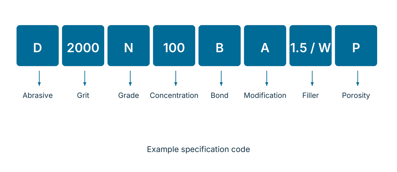
The marking separates the specification into abrasive, grit, grade, concentration, bond, bond modification, filler and porosity. The example shows D | 2000 | N | 100 | B | A | 1.5 or W | P. Numeric filler designations apply to resin bonds, and letter designations to vitrified bonds. Not every designation is required for every tool design.
| Field | Designations |
|---|---|
| Diamond types | D, ND, DM, CSD |
| CBN types | B, NB, BM, NBM |
| Normal grit sizes (mesh) | 60, 80, 100, 120, 140, 170, 200, 230, 270, 325, 400 |
| Micron grit sizes (µm) | 40/60, 40/50, 30/40, 22/36, 20/30, 15/25, 8/16, 6/12, 4/8, 3/6, 2/4, 0/2 |
| Bond | B: resin; V: vitrified |
| Resin modifications | BA, BB, BC, BCT, BD, BE, BG, BH, BP, BQ, BX, BXT, BXC, PAE, PA8, BMX |
| Vitrified modifications | VB, VBT, VE, VA, VD, VCL, VH |
| Resin filler designations | 1.5, 2, 3, 4, 5, 6, 7, 8, 10 |
| Vitrified filler designations | W, M, G, A, N, V, Z |
| Vitrified porosity designations | B, F, P, U, Y, I, C |
| Grade | Classification |
|---|---|
| J | Soft |
| N | Medium |
| R | Hard |
| Concentration | Abrasive content |
|---|---|
| 25 | 1.1 ct/cm³ |
| 50 | 2.2 ct/cm³ |
| 75 | 3.3 ct/cm³ |
| 100 | 4.4 ct/cm³ |
| 125 | 5.5 ct/cm³ |
| 150 | 6.6 ct/cm³ |
| 175 | 7.7 ct/cm³ |
| 200 | 8.8 ct/cm³ |
EHWA marking: metal bond
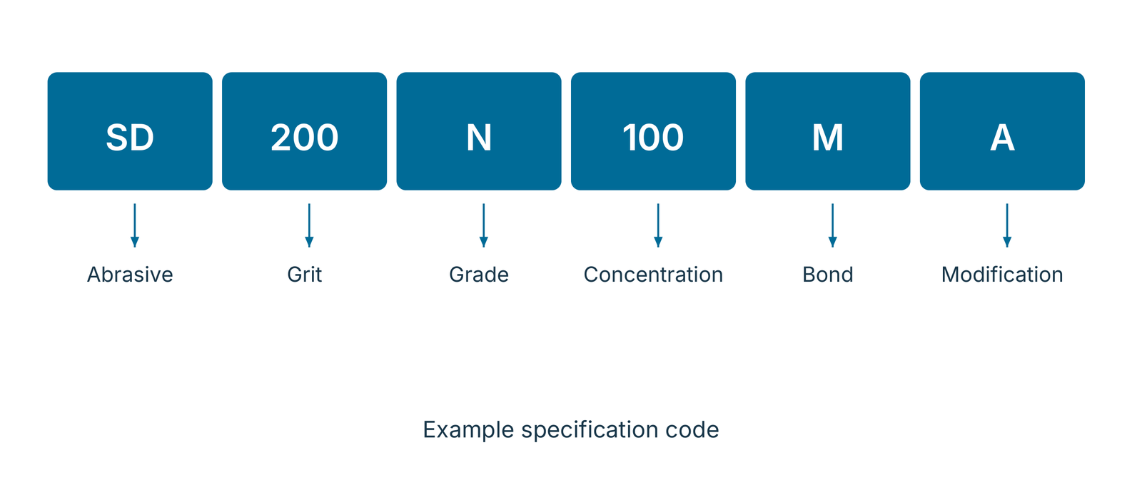
The example SD | 200 | N | 100 | M | A shows the sequence of abrasive, grit, grade, concentration, bond and modification. M denotes the metal bond. The modification list includes both series and specific grade designations.
| Field | Designations |
|---|---|
| Diamond types | SD, SDC, SDM |
| CBN types | CBN, CBS, CBM |
| Normal grit sizes (mesh) | 20, 30, 40, 50, 60, 80, 100, 120, 140, 170, 200, 230, 270, 325, 400 |
| Micron grit sizes (µm) | 40/60, 30/40, 22/36, 15/25, 10/20, 8/16 |
| Bond | M: metal |
| Modifications | MB21, MC9, MA, MF, MP1, ME4, MG7, MG21N, MX32, MX4, MFS, MX56, MX57 |
| Grade | Classification |
|---|---|
| G, H, I | Very soft |
| J, K, L, M | Soft |
| N | Normal |
| P, Q, R | Hard |
| Concentration | Abrasive content |
|---|---|
| 25 | 1.1 ct/cm³ |
| 50 | 2.2 ct/cm³ |
| 75 | 3.3 ct/cm³ |
| 100 | 4.4 ct/cm³ |
| 125 | 5.5 ct/cm³ |
| 150 | 6.6 ct/cm³ |
Diamond and CBN types for resin and vitrified bonds
Coating, grain form and size influence retention and cutting behaviour. The eight types therefore distinguish material mapping, bond and wet/dry operation. The listed grit ranges belong to the respective catalogue specification.
| Type | Features and application | Grit range |
|---|---|---|
| D | Diamond, uncoated; friable, irregular shape. General carbide grinding. Resin and vitrified bonds; mainly wet. | #60–#3000 |
| ND | Nickel-coated diamond with good bondability. Carbide, ceramics, cermet, glass and ferrite. Resin bond; wet or dry. | #60–#400 |
| DM | Micron diamond; friable, regular shape. Lapping and polishing of carbide, ceramics and glass. Resin and vitrified bonds; wet only. | D40/60–D0/2 |
| CSD | Nickel-coated diamond; high strength and excellent bondability. Combination grinding of carbide and hardened steel. | #60–#400; D40/60–D20/30 |
| B | CBN, uncoated. General grinding of bearings, camshafts, rolls and dies. Vitrified bond; wet only. | #60–#325 |
| NB | Nickel-coated CBN with good bondability. Hardened steels such as HSS, SKD-11 and SUS. Resin bond; wet or dry. | #60–#400 |
| BM | Uncoated micron CBN for lapping and polishing. Vitrified bond; wet only. | G45, G30, G15 |
| NBM | Nickel-coated micron CBN for lapping and polishing. Resin bond; mainly wet. | G45, G30, G15 |
Diamond and CBN types for metal bonds
Metal-bond types distinguish blocky, tough diamond grains and CBN types for ferrous materials. Printed range designations are retained for micron grits. The CBM row also uses the letter D; tool orders should identify the CBM abrasive type together with the required grain-size range.
| Type | Features and application | Grit range |
|---|---|---|
| SD | Special synthetic diamond; blocky form, high toughness. | #60–#400 |
| SDC | Coated special synthetic diamond; blocky form, high toughness. | #60–#400 |
| SDM | Micron diamond; blocky, regular form. Precision grinding and polishing. | D40/60–D1/2 |
| CBN | Ferrous alloys and cast steel. | #60–#400 |
| CBS | Special CBN for hardened steels: HSS, SKD-11, SCM, SUS. | #60–#400 |
| CBM | Micron CBN for precision grinding. | D40/60–D2/4 |
Resin bonds: modifications and relative hardness
The bond series distinguish elasticity, heat transfer, shape retention and removal performance. Features describe the respective application design. The second table shows hardness order within specific wheel forms, from soft to hard.
| Code | Features and application |
|---|---|
| BA | Good elasticity; grinding depth about 10 µm. Mainly micron abrasives for carbide, hardened steel and PCD. |
| BB | Good heat transfer in dry grinding. Particularly CBN for HSS regrinding; mainly cup wheels. |
| BC | Good heat transfer and shape retention. Fluting of HSS endmills, reamers and drills. |
| BCT | CNC machining with 11V9 and 12V9 cup wheels. |
| BD | Very soft; low noise and good form/surface quality. General grinding of carbide, ceramics and glass. |
| BE | Heavy-duty CBN grinding for HSS regrinding; also dry operation. |
| BG | Standard bond for varied workpieces. Profile, face, cylindrical and centreless grinding. |
| BH | Good shape retention and heat transfer. Profile and face grinding. |
| BP | Lubricating bond; applications as for BG, but softer. |
| BQ | Finishing of glass and quartz. |
| BX | Good cutting ability. Fluting of endmills, reamers and carbide tools by creep-feed grinding. |
| BXT | Applications as for BX, but harder. |
| BXC | Grinding of cermet and ceramic inserts. |
| PAE | High-temperature polyimide bond for carbide microtools. |
| PA8 | High-temperature polyimide bond for small to medium carbide tools. |
| BMX | Hybrid bond for heavy stock removal in carbide tool grinding. |
| Wheel form | Order: soft → hard |
|---|---|
| D11V9 | BG → BE → BCT |
| B11V9 | BB → BE → BCT |
| 1A1 | BA → BP → BG → BH → BX |
| 1A1R | BD → BG → BH |
| 4A2/6A2/2A2T | BA → BB → BG → BE → BH → BC → BX → BXT |
Vitrified bonds: balancing performance and tool life
The seven modifications support application-based selection between grinding performance, machining load, surface quality and tool life. Comparisons such as “harder” or “shorter life” refer to the bond series specifically named.
| Code | Features and application |
|---|---|
| VB | General CBN bond for bearings, camshafts, rolls, constant-velocity joints and dies. |
| VBT | Development of VB for reduced machining load; also used together with VB for improved grinding performance. |
| VE | Targets grinding performance and surface roughness; reduces machining load, but shorter life than VB. |
| VA | For diamond and CBN. In CBN applications, performance and life lie between VB and VE. For diamond, harder than VD and suitable for longer life. |
| VD | General diamond bond for carbide, PCD and PCBN. |
| VCL | For crushing wheels. Higher grinding performance than VD, but shorter life than VD. |
| VH | Targets low chipping, particularly PCBN and honing stones. Shorter life than VD and VCL. |
Metal bonds: composition and application
Bronze, iron and cobalt components, or special bronze bonds, underpin the metal-bond series. The table retains all 13 grades with their compositions, applications and relative hardness mappings.
| Code | Bond basis | Features and application |
|---|---|---|
| MB21 | Bronze | Glass and lens machining. |
| MC9 | Bronze and iron | Harder than MB21; designed for longer wheel life in glass and lens applications. |
| MA | Bronze | Ceramics, hardened steel and carbide. |
| MF | Bronze | Sharp-edged profile wheels for hardened steel and carbide. |
| MP1 | Bronze and cobalt | Sharp-edged profile wheels for carbide. |
| ME4 | Bronze and cobalt | Mainly automotive glass on automatic machines. |
| MG7 | Iron | Automotive glass and CNC machines. |
| MG21N | Iron | Automotive glass on CNC machines for longer life; harder than MG7. |
| MX32 | Special bronze bond | Good grinding performance; general carbide grinding. |
| MX4 | Special bronze bond | Softer than MX32; roughing carbide and cermet, also sapphire. |
| MFS | Special bronze bond | Softer than MX4; finishing carbide and cermet, also sapphire. |
| MX56 | Special bronze bond | Diamond grinding and polishing; grit #3000–#5000. |
| MX57 | Special bronze bond | Electrolytically assisted polishing and crushing grinding. |
Wheel shape overview
The overview covers 36 tool forms. The following dimension diagrams combine sections, front views and spatial tool models. The grinding layer is distinguished from the body; letter designations describe the respective dimensions. The shape overview does not specify fixed order dimensions.
| Form group | Types |
|---|---|
| 1 | 1A1, 1A1R, 1A8, 1E1 |
| 2 | 1E6Q, 1EE1, 1FF1, 1FF6Y |
| 3 | 1V1, 2A2T, 2FF2, 3A1 |
| 4 | 4A2, 4B2, 4M1, 6A2 |
| 5 | 6A2C, 6A9, 6F2, 9A3 |
| 6 | 11A2, 11B2, 11C9, 11V9 |
| 7 | 11Y9, 12A2, 12V4, 12V9 |
| 8 | 14A1, 14EE1, 14U1, DW |
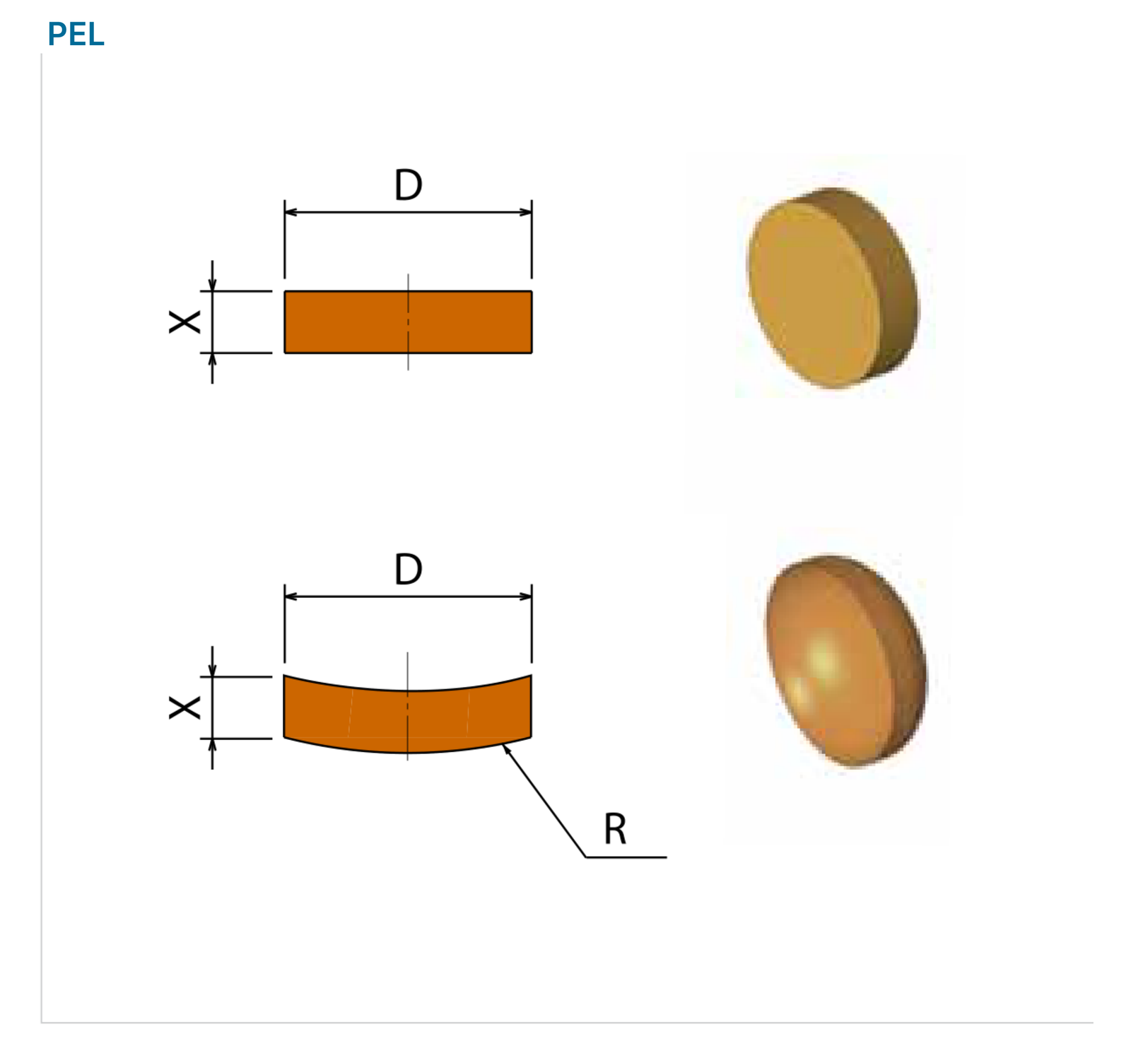
| 9 | BUL, HH1, HMF, PEL |
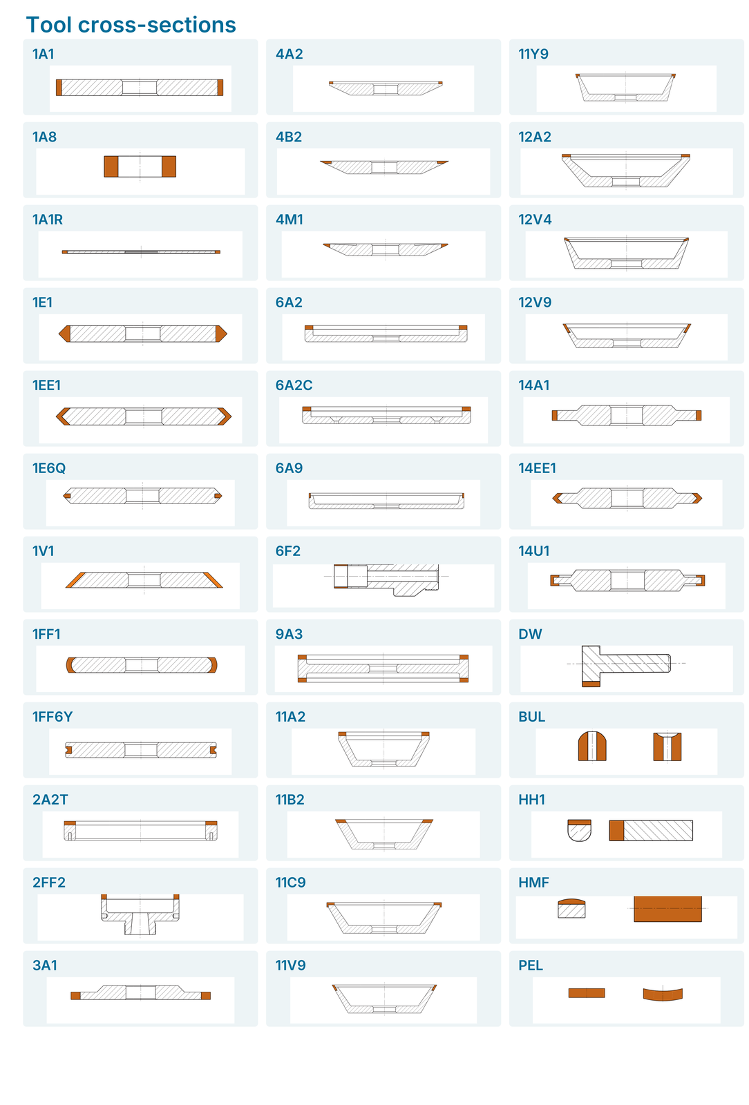
Dimension diagrams: 1A1, 1A1R, 1A8, 1E1
Dimension designations apply to the illustrated tool profile. Sections and front views show the locations of the grinding layer, mounting features and other form details.
| Type | Dimension designations |
|---|---|
| 1A1 | D T X H |
| 1A1R | D T W T1 H |
| 1A8 | D T X |
| 1E1 | D T X H V |

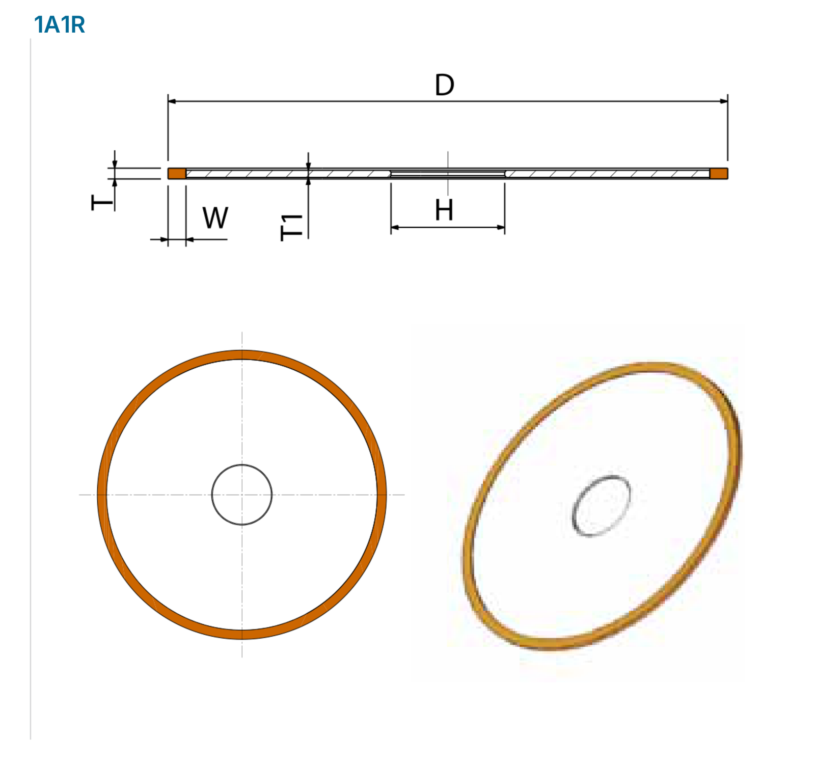

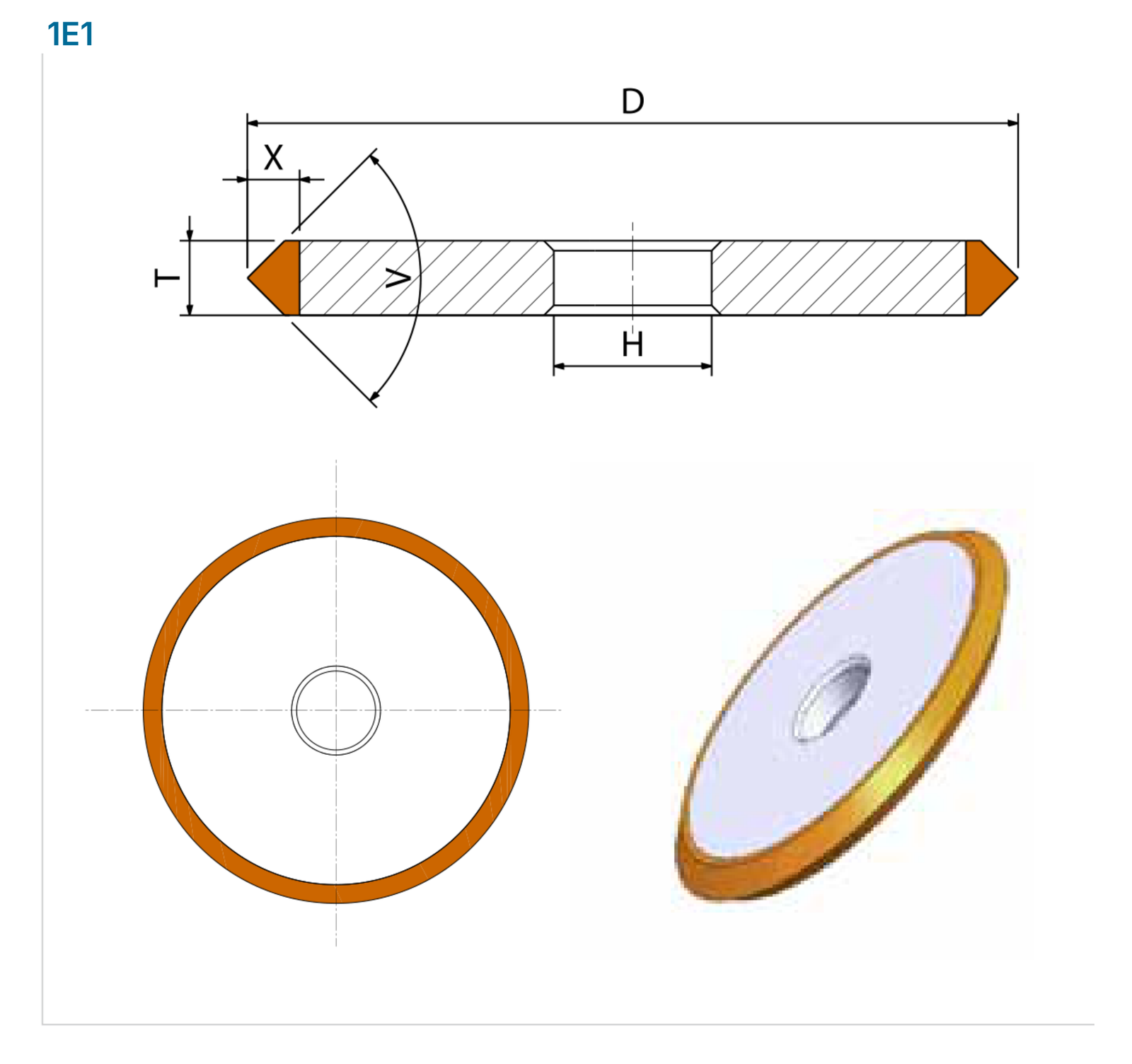
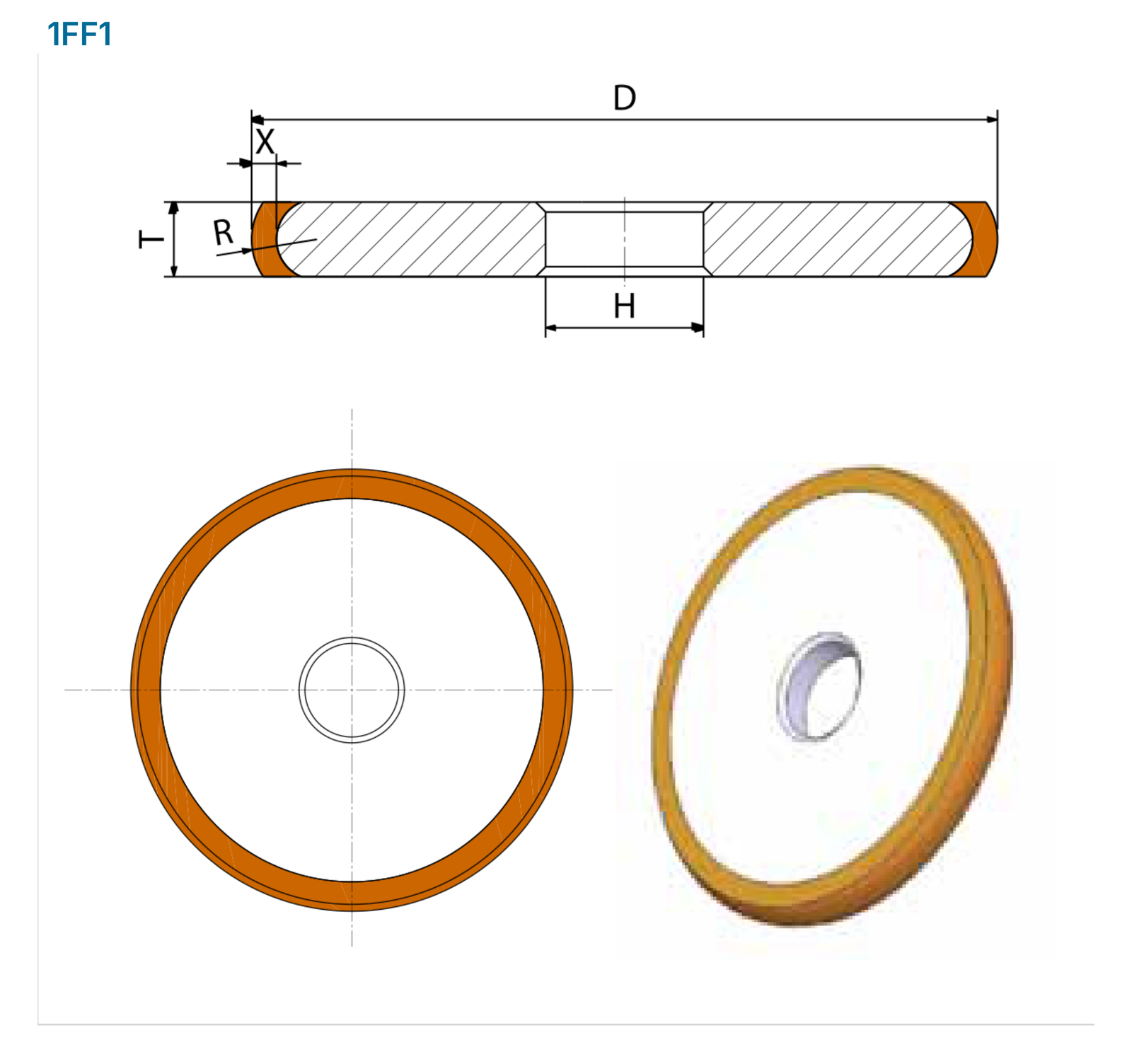
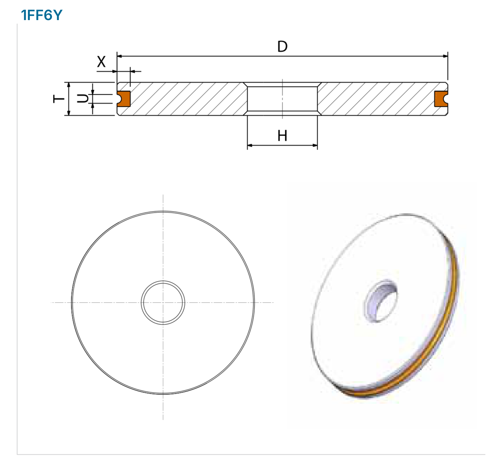
Dimension diagrams: 1E6Q, 1EE1, 1FF1, 1FF6Y
Dimension designations apply to the illustrated tool profile. Sections and front views show the locations of the grinding layer, mounting features and other form details.
| Type | Dimension designations |
|---|---|
| 1E6Q | D T U X H V |
| 1EE1 | D T X H V |
| 1FF1 | D T X H R |
| 1FF6Y | D T U X H |

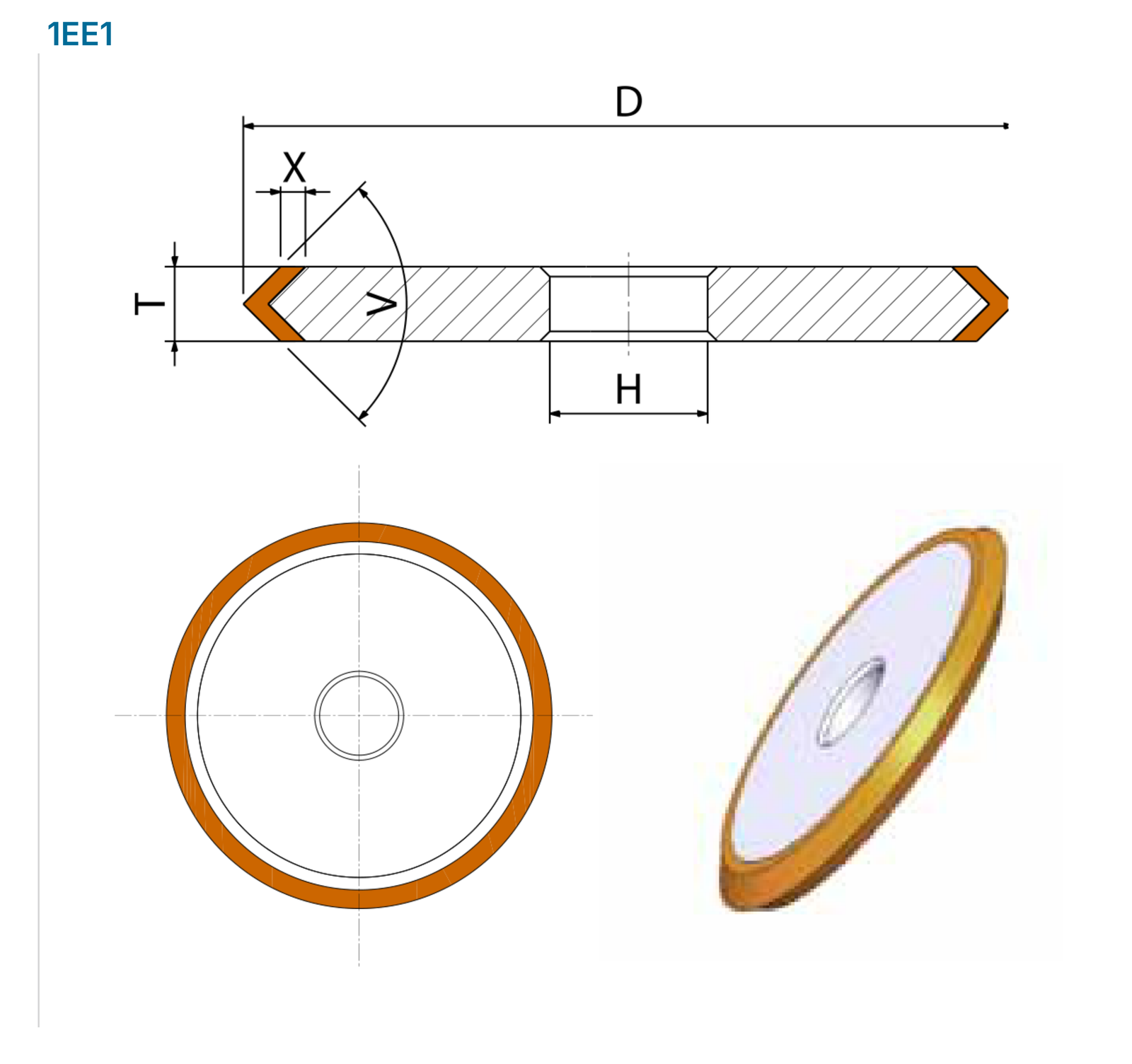
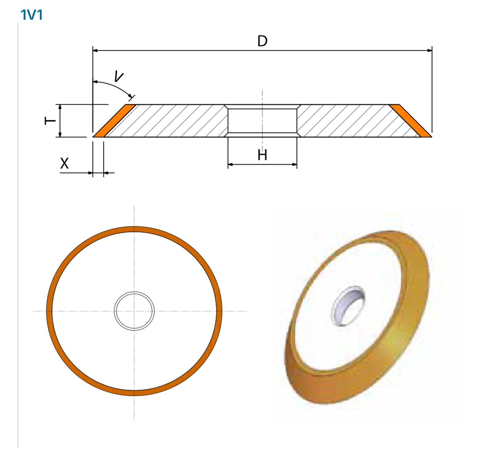
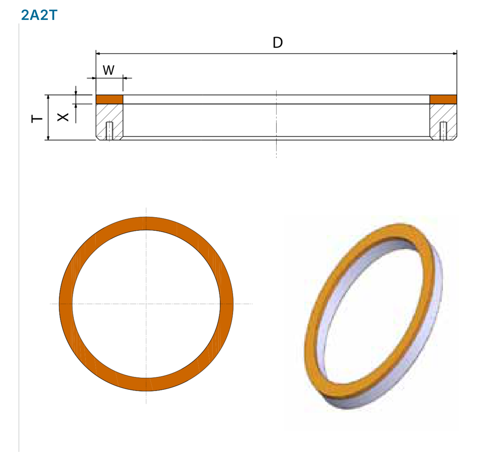
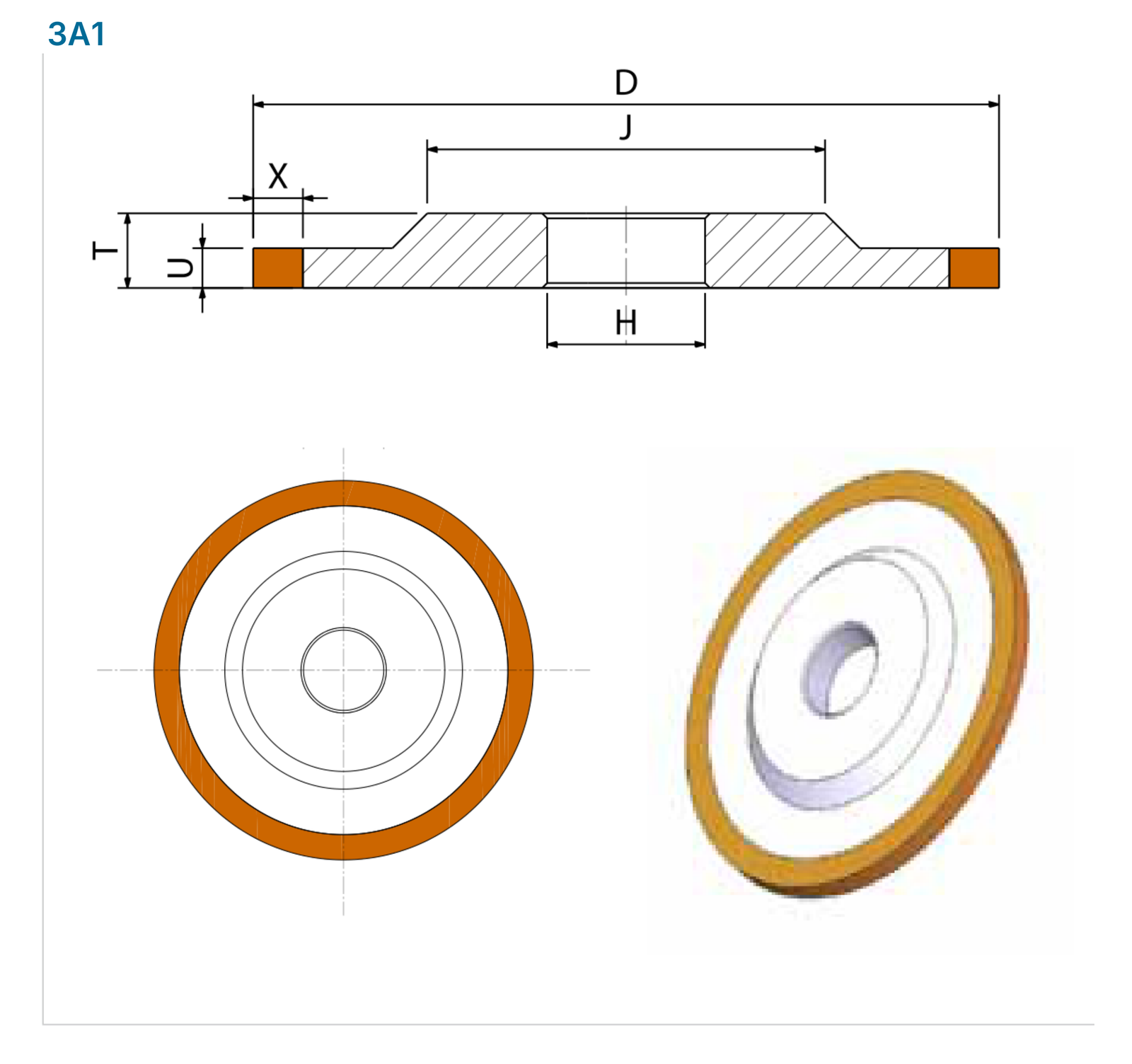
Dimension diagrams: 1V1, 2A2T, 2FF2, 3A1
Dimension designations apply to the illustrated tool profile. Sections and front views show the locations of the grinding layer, mounting features and other form details.
| Type | Dimension designations |
|---|---|
| 1V1 | D T X H V |
| 2A2T | D T X W |
| 2FF2 | D T X W M SV |
| 3A1 | D T U X J H |

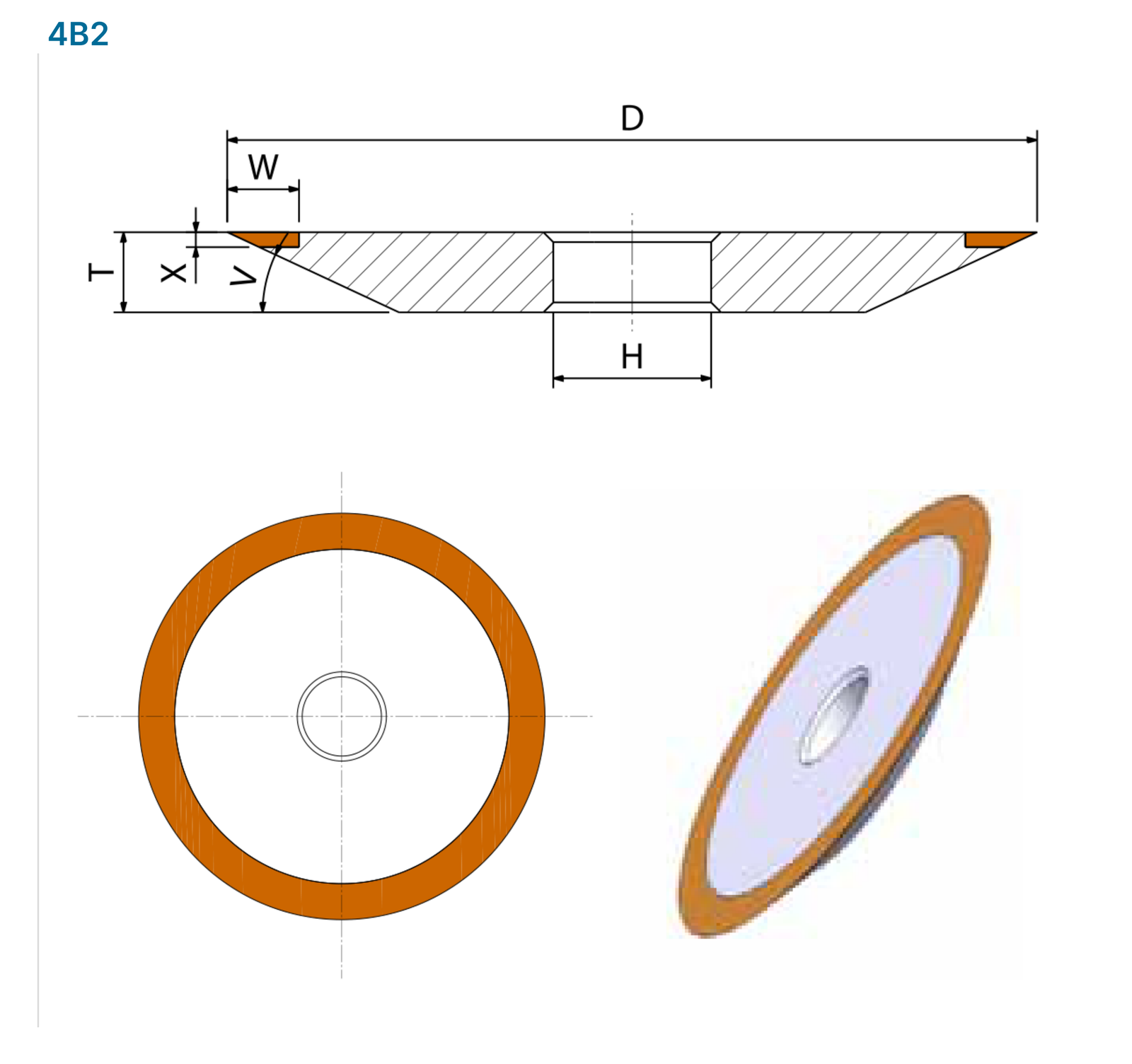
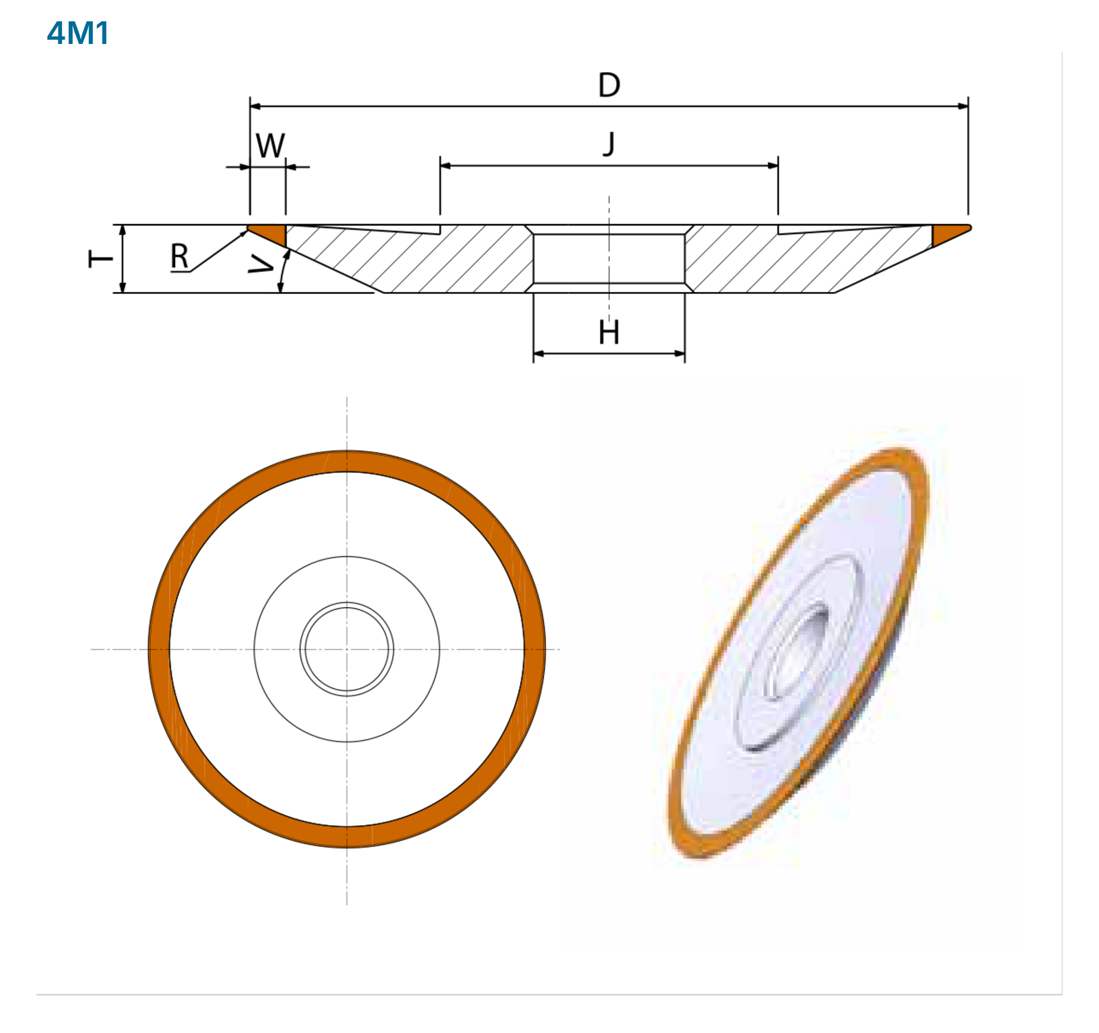
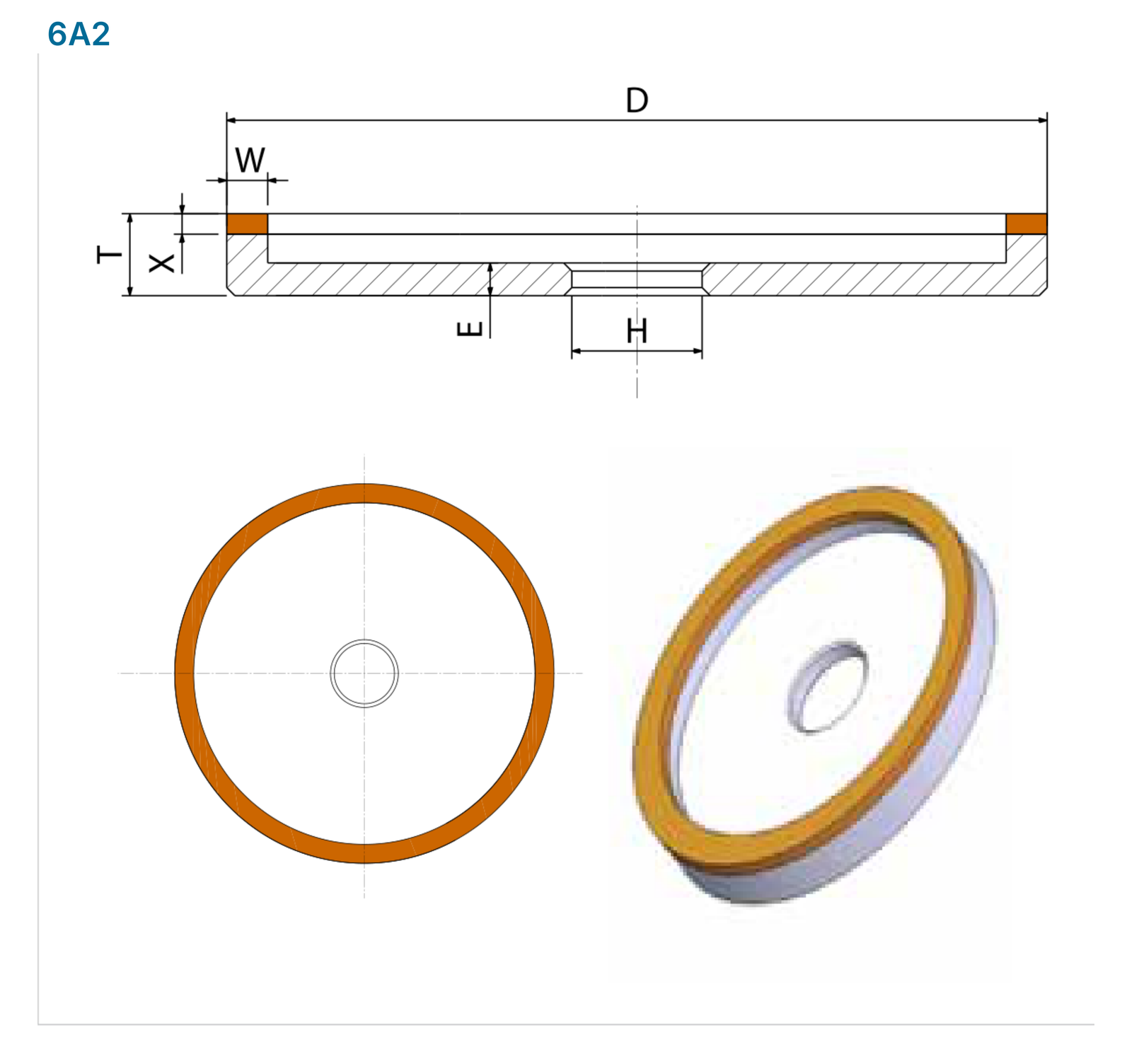
Dimension diagrams: 4A2, 4B2, 4M1, 6A2
Dimension designations apply to the illustrated tool profile. Sections and front views show the locations of the grinding layer, mounting features and other form details.
| Type | Dimension designations |
|---|---|
| 4A2 | D T X W H V |
| 4B2 | D T X W H V |
| 4M1 | D T W J H V R |
| 6A2 | D T X W H E |

Dimension diagrams: 6A2C, 6A9, 6F2, 9A3
Dimension designations apply to the illustrated tool profile. Sections and front views show the locations of the grinding layer, mounting features and other form details.
| Type | Dimension designations |
|---|---|
| 6A2C | D T X W H E P |
| 6A9 | D T U X H E |
| 6F2 | D W X L L1 Y M |
| 9A3 | D T X W H E |
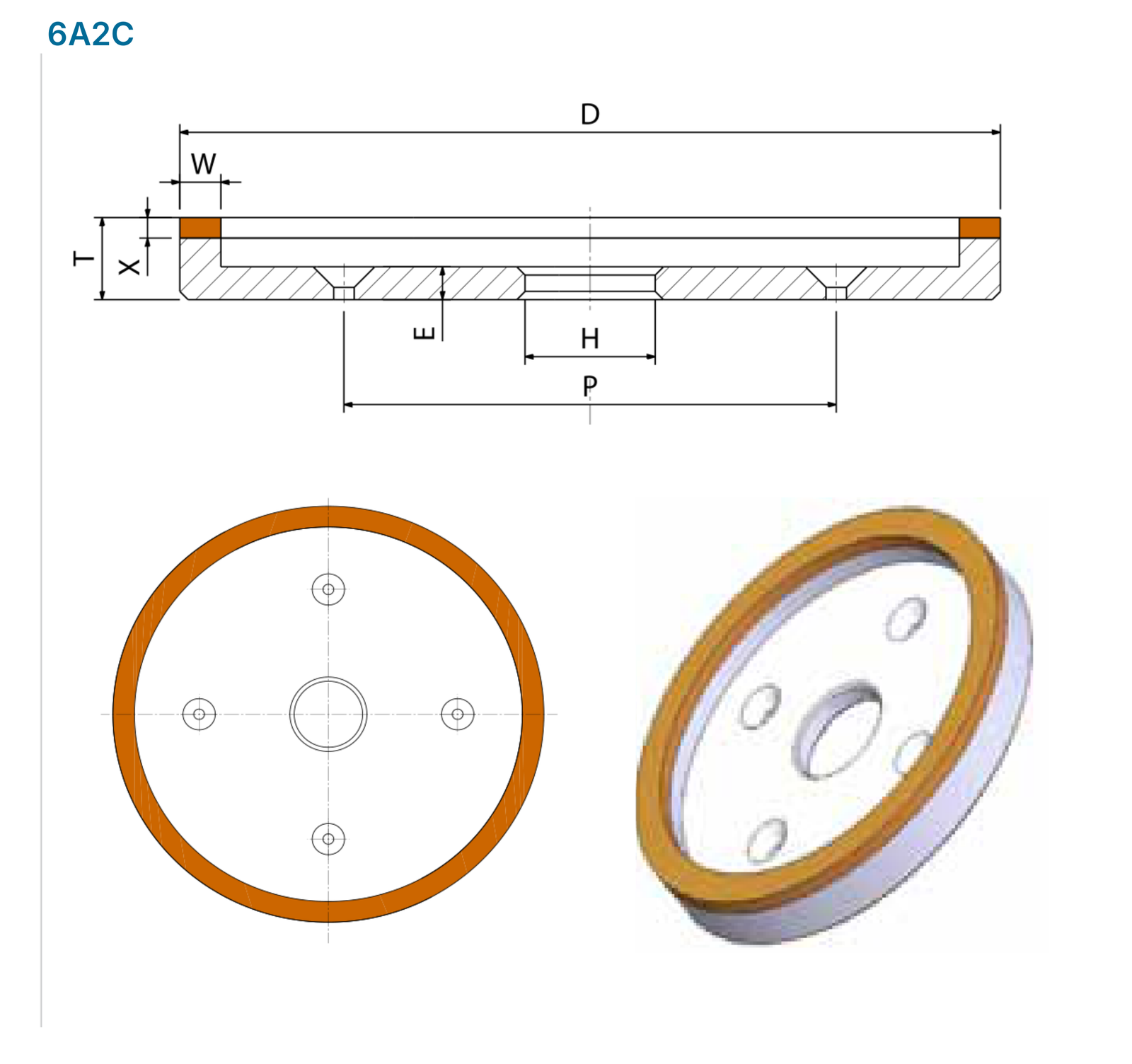
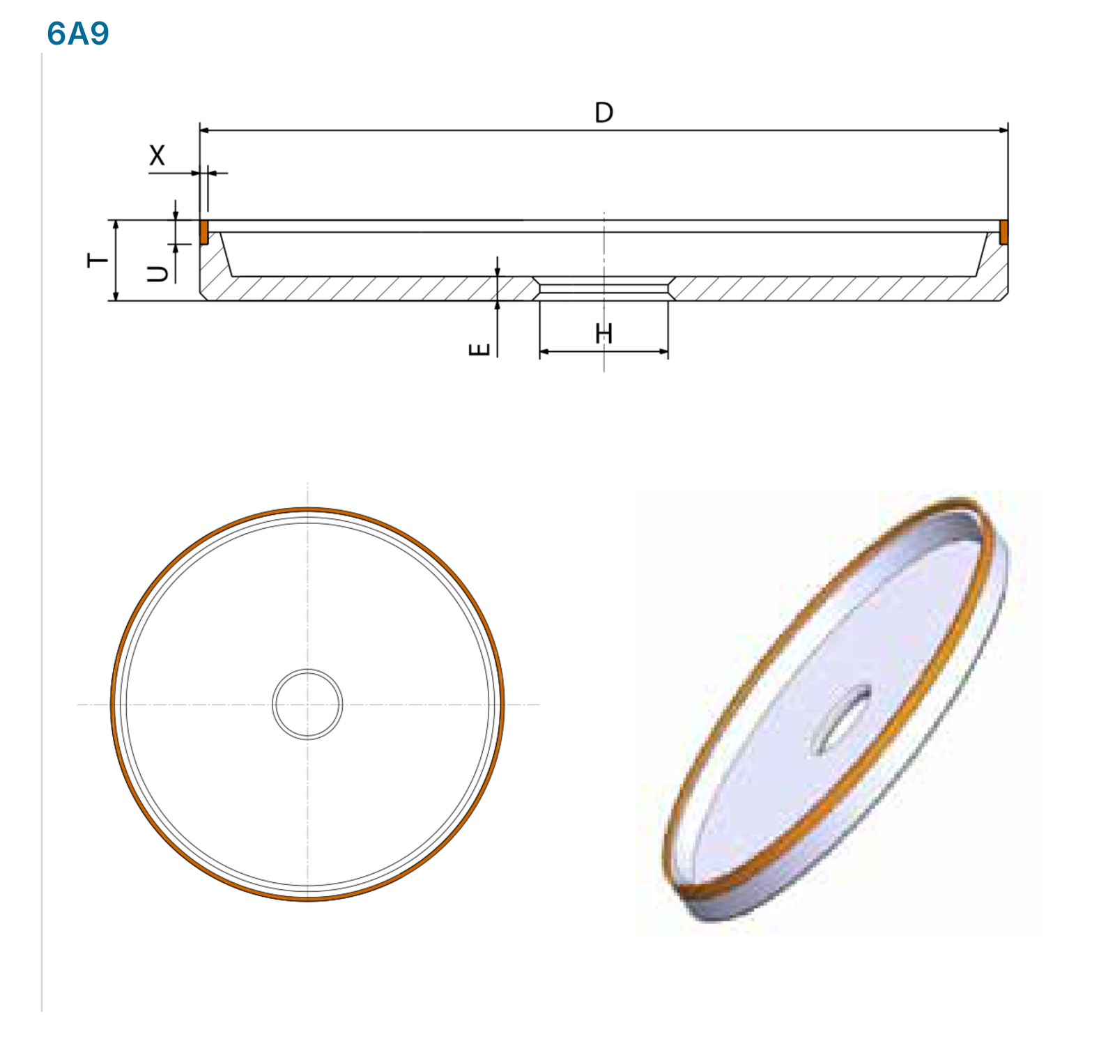
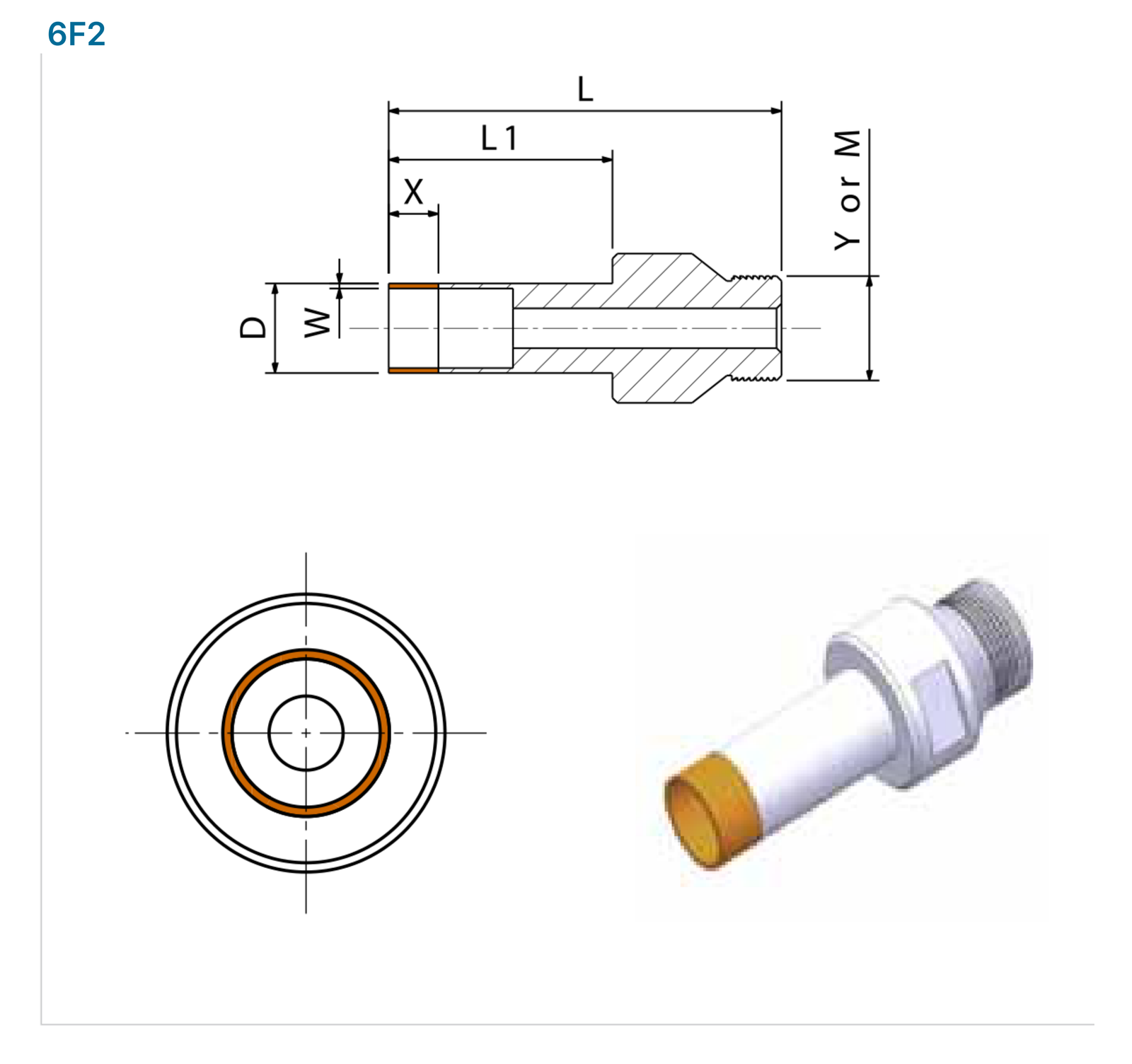
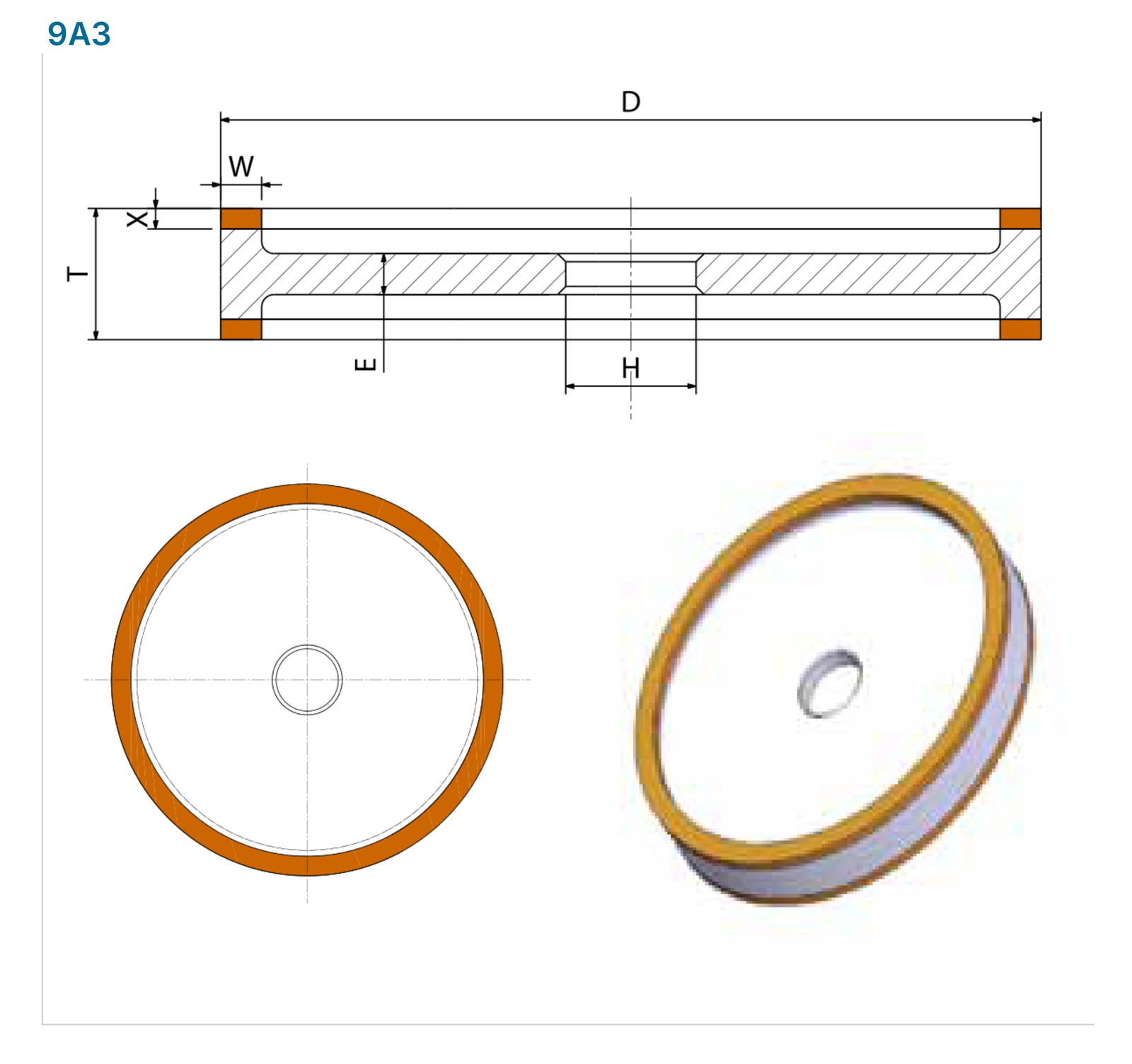
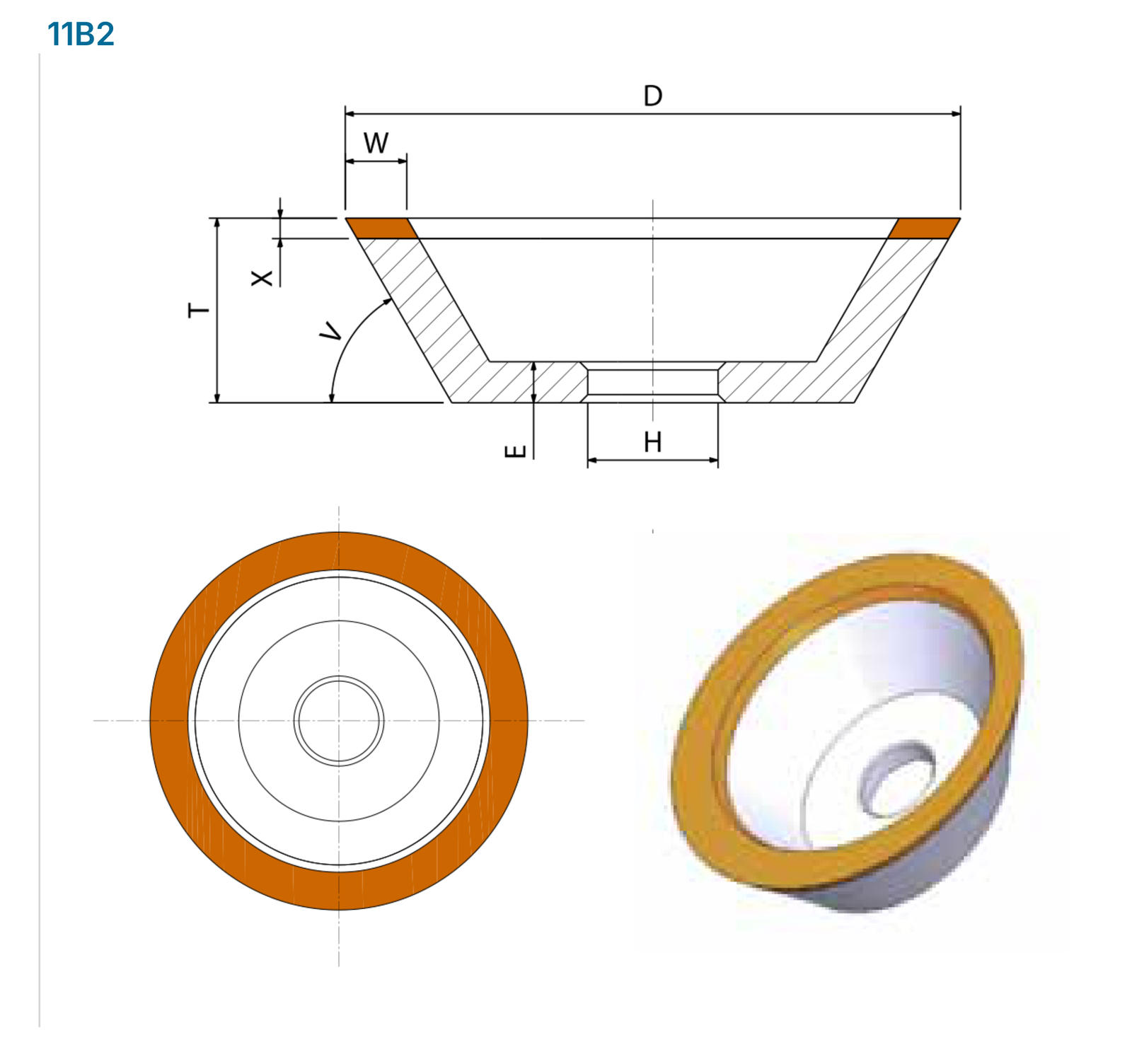
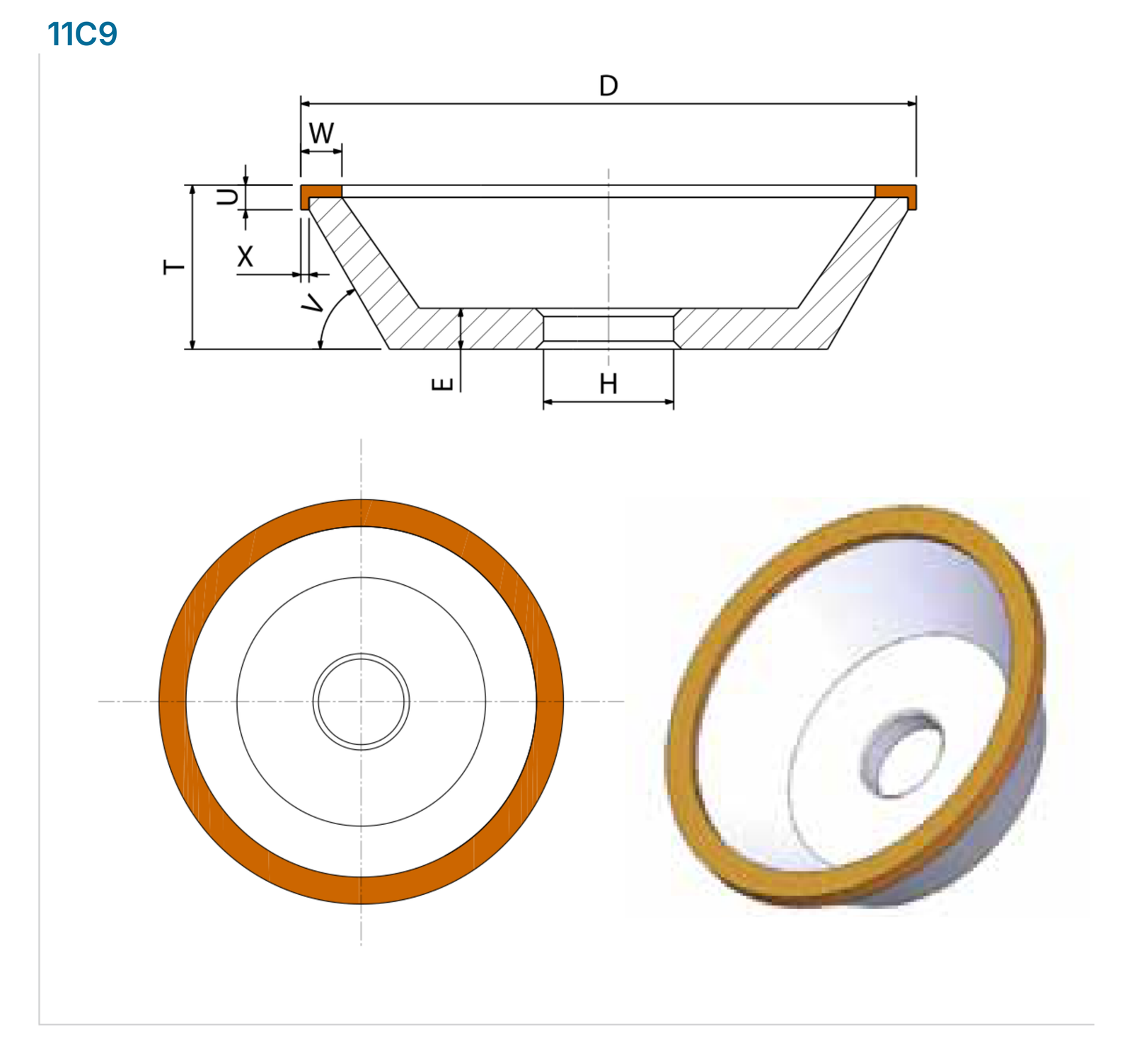
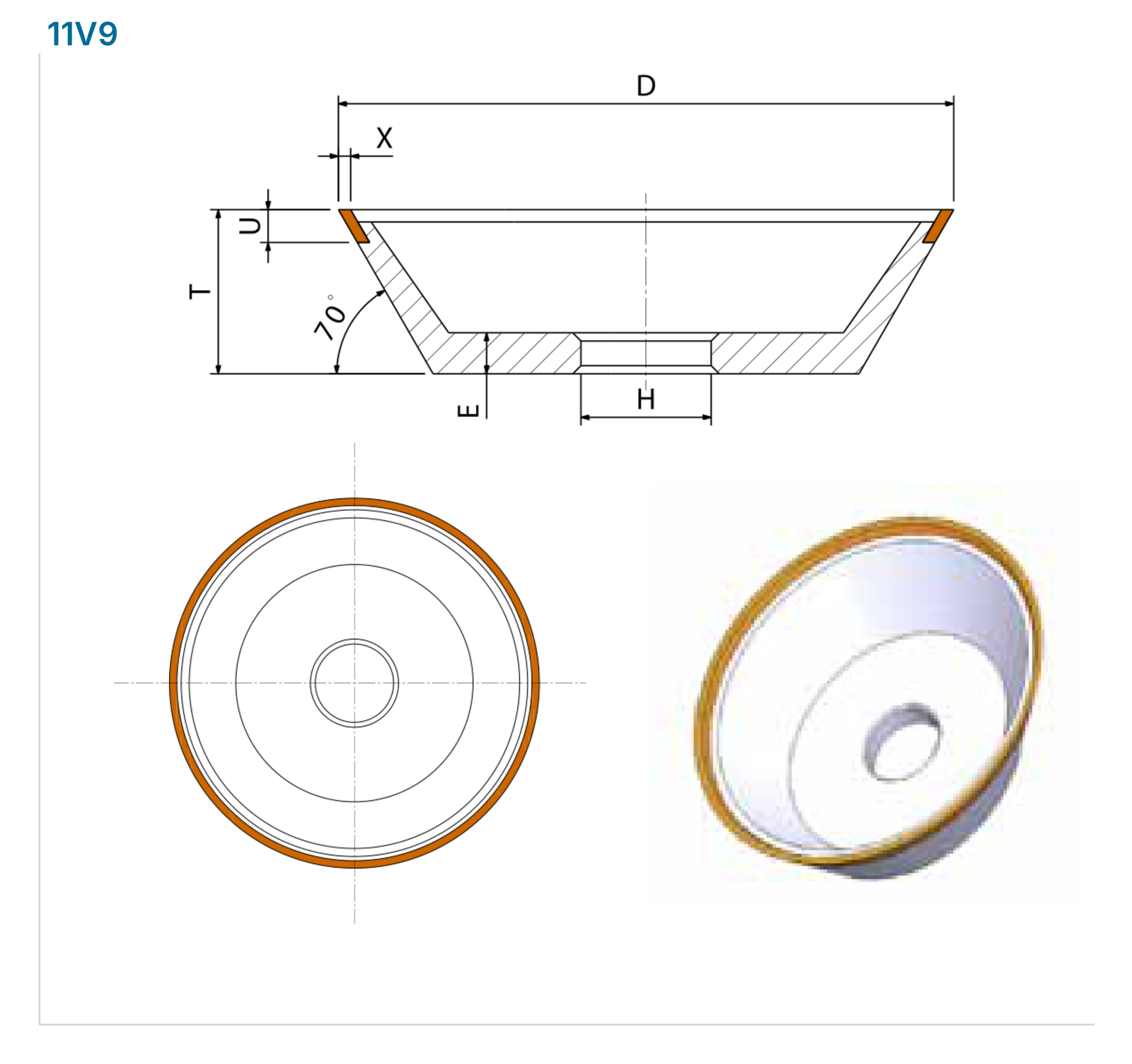
Dimension diagrams: 11A2, 11B2, 11C9, 11V9
Dimension designations apply to the illustrated tool profile. Sections and front views show the locations of the grinding layer, mounting features and other form details.
| Type | Dimension designations |
|---|---|
| 11A2 | D T X W H E V |
| 11B2 | D T X W H E V |
| 11C9 | D T U X W H E V |
| 11V9 | D T U X H E 70° |

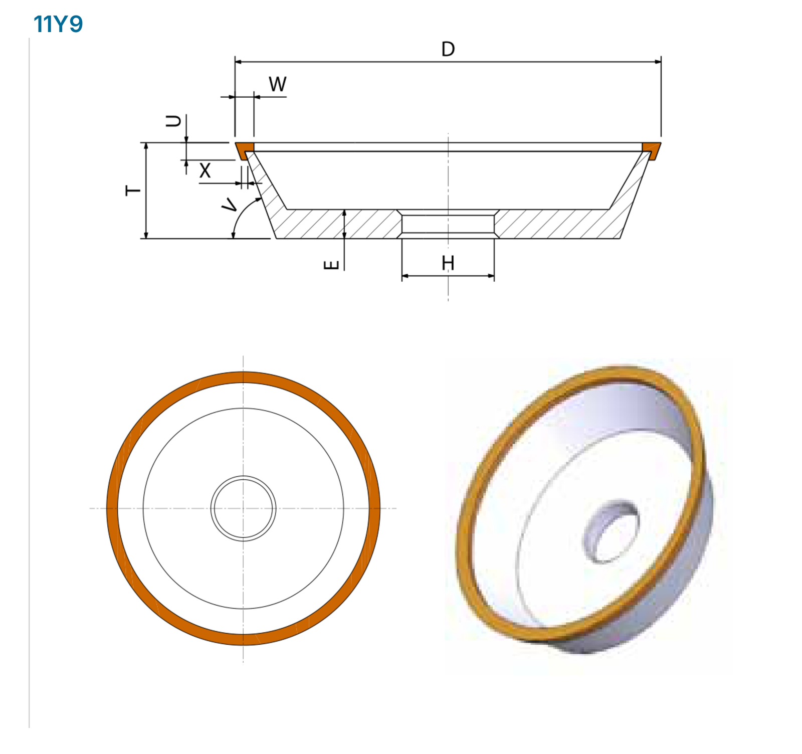
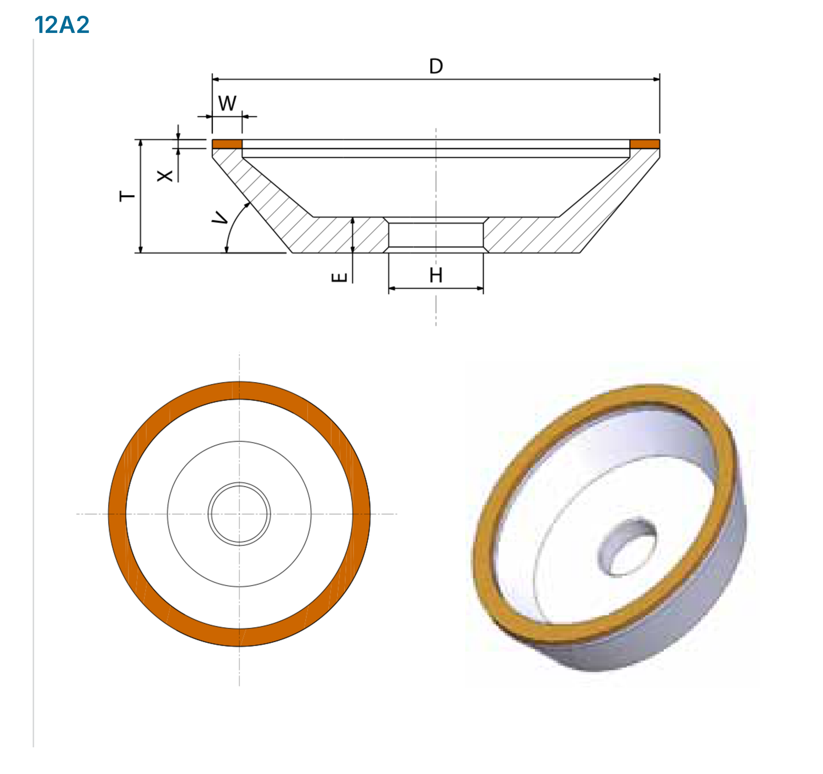
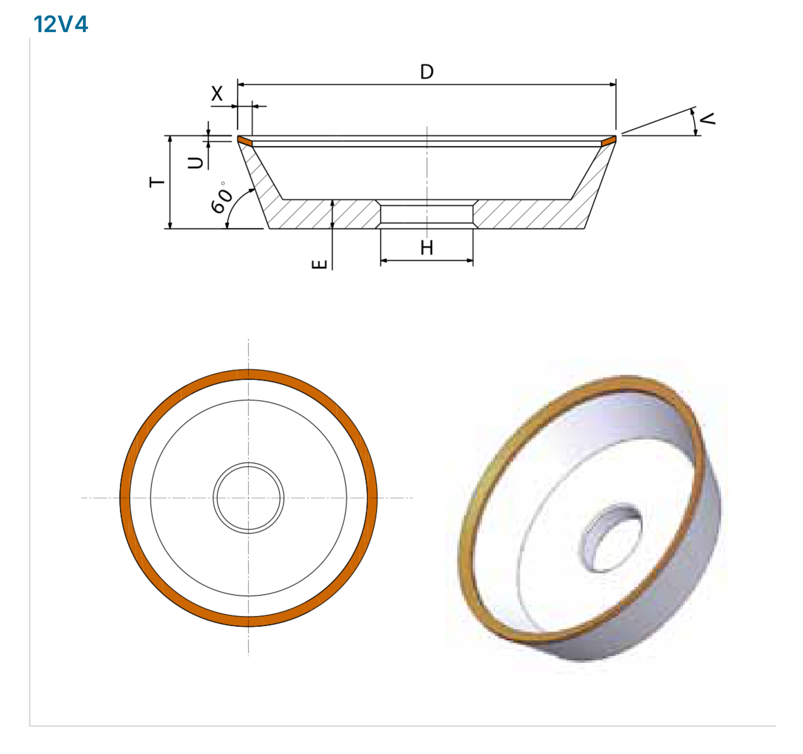
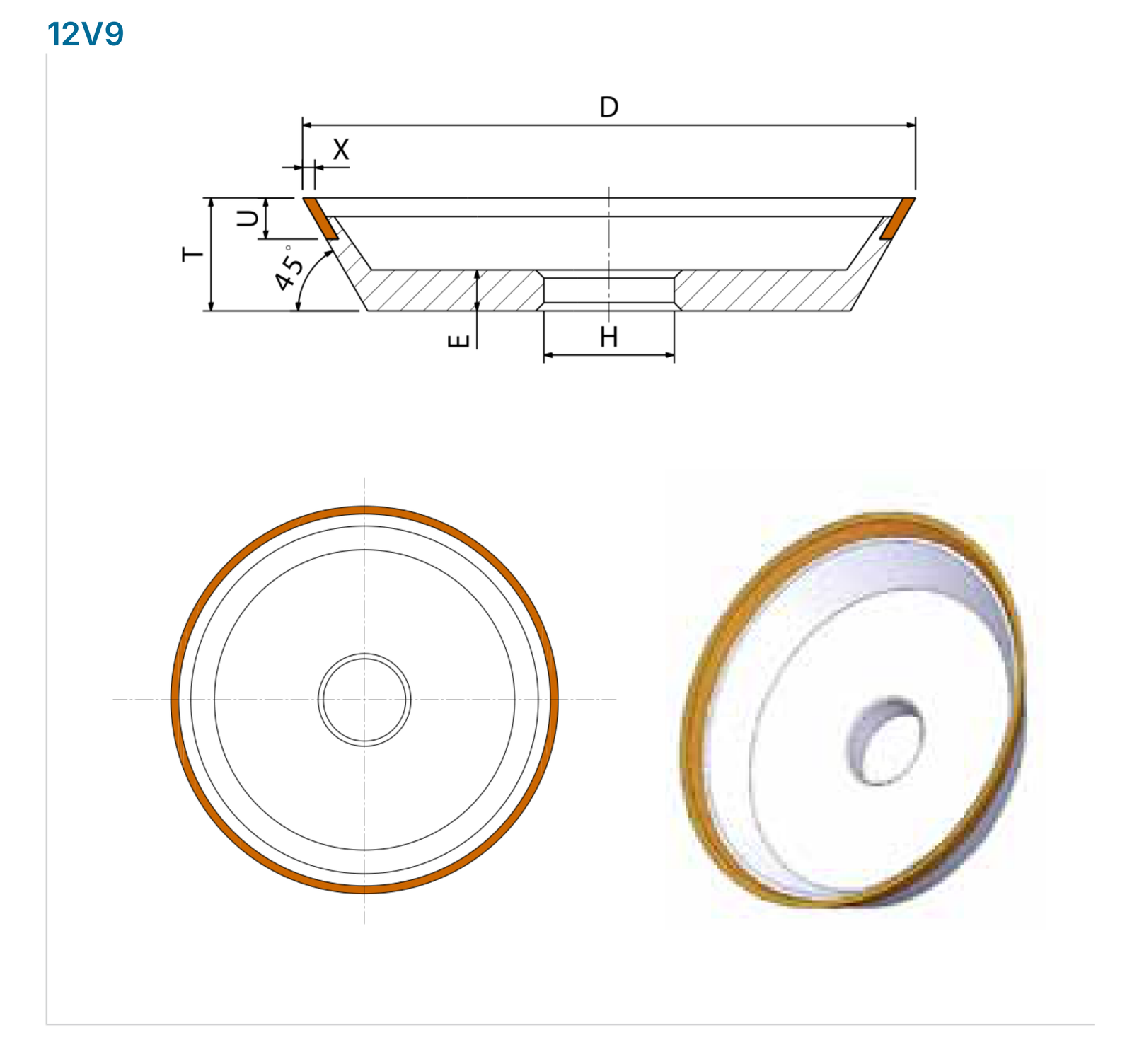
Dimension diagrams: 11Y9, 12A2, 12V4, 12V9
Dimension designations apply to the illustrated tool profile. Sections and front views show the locations of the grinding layer, mounting features and other form details.
| Type | Dimension designations |
|---|---|
| 11Y9 | D T U X W H E V |
| 12A2 | D T X W H E V |
| 12V4 | D T U X H E V 60° |
| 12V9 | D T U X H E 45° |
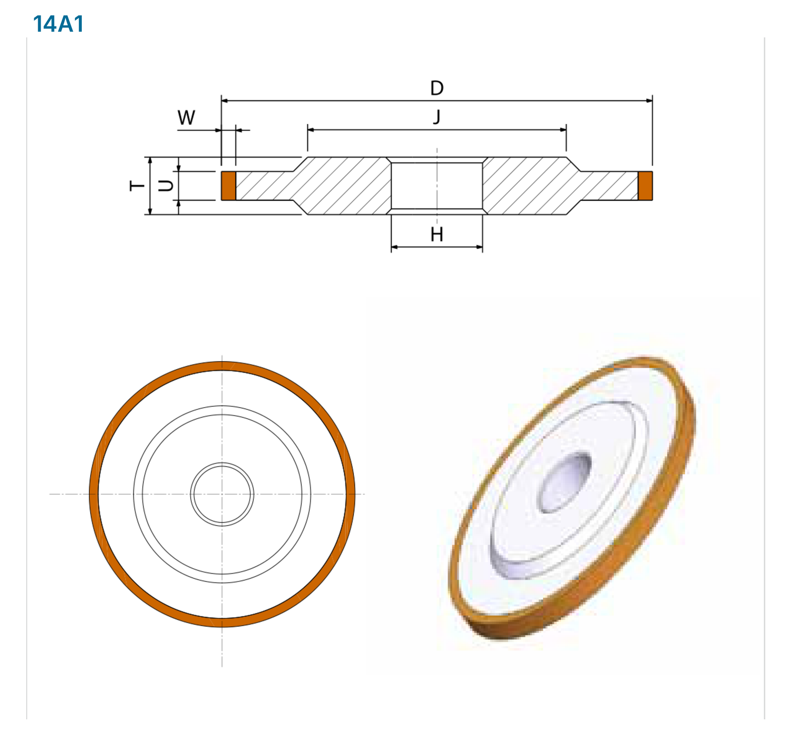
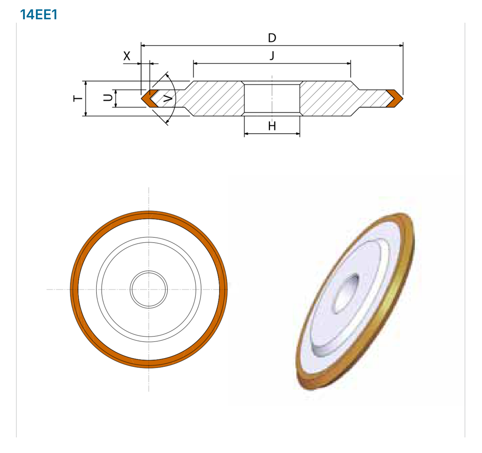
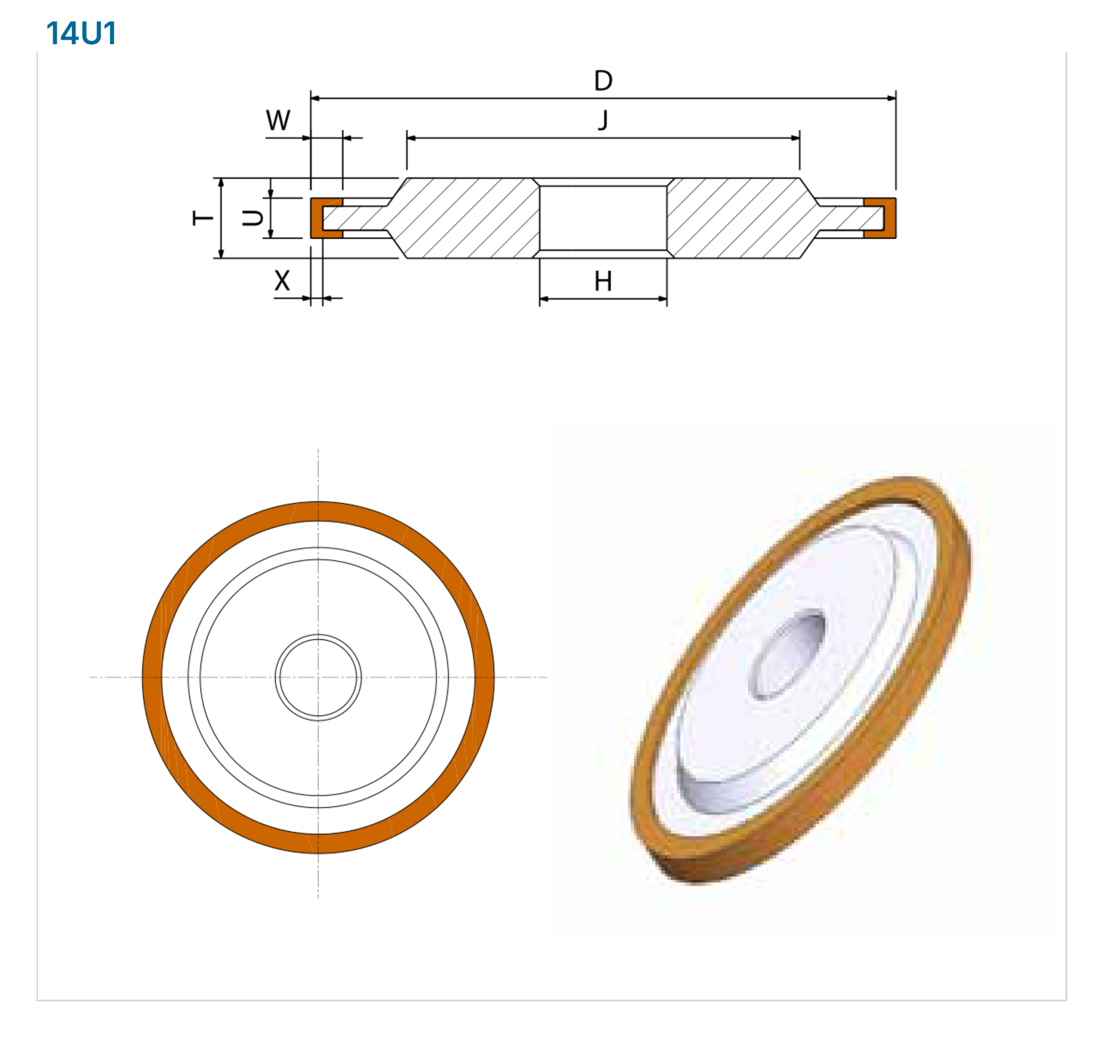
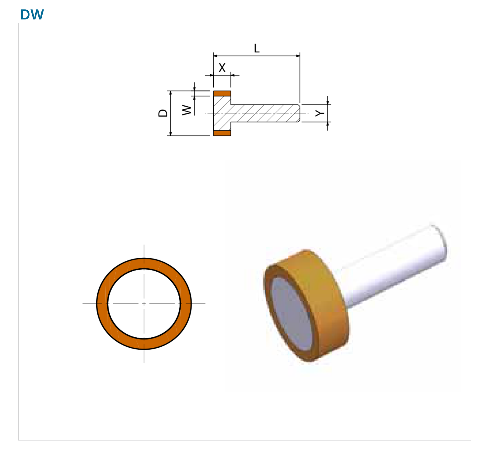
Dimension diagrams: 14A1, 14EE1, 14U1, DW
Dimension designations apply to the illustrated tool profile. Sections and front views show the locations of the grinding layer, mounting features and other form details.
| Type | Dimension designations |
|---|---|
| 14A1 | D T U W J H |
| 14EE1 | D T U X J H V |
| 14U1 | D T U W X J H |
| DW | D W X L Y |
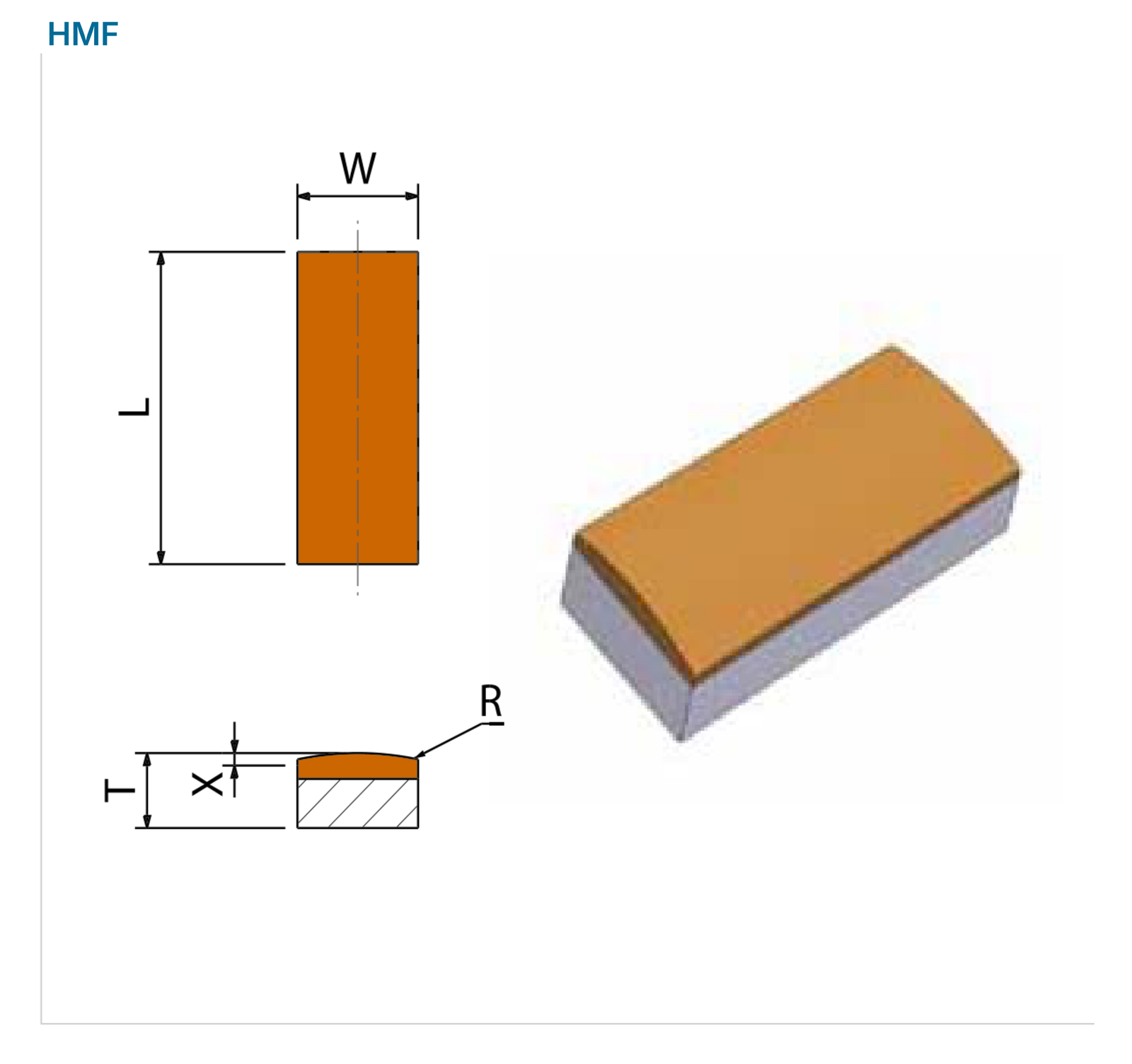
Dimension diagrams: BUL, HH1, HMF, PEL
Dimension designations apply to the illustrated tool profile. Sections and front views show the locations of the grinding layer, mounting features and other form details.
| Type | Dimension designations |
|---|---|
| BUL | D T H R |
| HH1 | L L1 W T X |
| HMF | L W T X R |
| PEL | D X R |


Key to dimension letters
Dimension diagrams support selection of shape and type. Each designation describes the feature marked in its drawing. Please also specify dimensions that are not filled in a selection. Additional designations such as T1, L1, M, SV and P belong to the respective dimension diagram.
| Code | Meaning |
|---|---|
| B.C. | Bolt circle |
| D | Wheel diameter |
| d | Description of mounting hole |
| E | Back thickness |
| H | Hole size |
| J | Hub diameter |
| R | Radius |
| T | Wheel thickness |
| S | Back angle |
| L | Length for types DW, HH1, HMF, 2FF2, 6F2 |
| n | Number of mounting holes |
| U | Diamond face for 3A1, 14A1, 14EE1, 14U1; abrasive insert length for 1E6Q, 6A9, 11C9, 11V9, 11Y9, 12V9 and pencil edgers |
| V | Face angle for 1V1, 4B2, 11B2, 12V4; included angle for 1E1, 1EE1, 1E6Q, 14EE1 |
| W | Rim width |
| X | Diamond/CBN depth |
| K | Inside flat diameter |
| Y | Shank diameter for DW and 6F2 |
Process guidance for diamond and CBN grinding tools
Abrasive, bond and tool form work together with the machine, mounting, coolant and operating conditions. The following guidance supports tool selection, mounting, preparation and economical use.
Diamond: abrasive, concentration and grit
Wheel diamond is divided into natural and synthetic diamond. Industrial use of synthetic diamond expanded in the 1950s; the source catalogue names 1957 as its introduction year. Development of tough, strong grains for saw blades and suitable grains for resin bonds broadened applications. Metal coatings can improve bondability. The catalogue description distinguishes 50 diamond-powder grades and maps them to resin, metal and vitrified bonds. Grain type and size are selected for the workpiece, bond and grinding conditions.
Concentration denotes diamond content per unit volume of the abrasive layer. Concentration 100 corresponds to 25 volume% or 4.4 ct/cm³. Concentration influences tooling cost; appropriate selection depends on material and process.
The grit overview contains 22 sizes. For sieve grits, the designation identifies the coarser end of the range: #140/170 passes the #140 sieve and is retained by #170, with #140 as the nominal designation. The catalogue treats sizes up to #325 as sieve grits, with a different classification for finer sizes.
The third column retains the printed catalogue designations. The diamond table mixes B and D designations, and not every sieve mapping matches a current standard mapping. Orders should establish abrasive type, actual size range and the grit system together.
| Grain content (volume%) | Concentration | Diamond content (ct/cm³) |
|---|---|---|
| 25 | 100 | 4.4 |
| 18.75 | 75 | 3.3 |
| 12.5 | 50 | 2.2 |
| 6.25 | 25 | 1.1 |
| Nominal grit (mesh) | Grit range (mesh) | Catalogue designation, “FEPA” column |
|---|---|---|
| 16 | 16/20 | — |
| 20 | 20/30 | B852 |
| 30 | 30/40 | B602 |
| 40 | 40/50 | B426 |
| 50 | 50/60 | B301 |
| 60 | 60/80 | B252 |
| 80 | 80/100 | B181 |
| 100 | 100/120 | B151 |
| 120 | 120/140 | B126 |
| 140 | 140/170 | D107 |
| 170 | 170/200 | D91 |
| 200 | 200/230 | D76 |
| 230 | 230/270 | D64 |
| 270 | 270/325 | D54 |
| 325 | 325/400 | D46 |
| 400 | — | — |
| 600 | — | — |
| 800 | — | — |
| 1000 | — | — |
| 1500 | — | — |
| 2000 | — | — |
| 3000 | — | — |
Diamond bonds, wheel diameter and contact area
Resin bonds are manufactured with phenolic resin or polyimide. The catalogue describes phenolic resin as a commonly used option. Good elasticity, surface finish and grinding performance support carbide grinding, combined machining of carbide and hardened steel, cermet machining, and precision grinding of magnetic materials, glass and ceramics. Polyimide bonds are particularly intended for heavy removal and creep-feed grinding.
Metal bonds are produced by sintering metal powder with diamond grains. Strong grain retention is beneficial where long life or low wheel wear is required, in hand grinding of carbide, profile grinding, and cutting or grinding of ceramics, glass, quartz, ferrite, stone and graphite. Strong retention can also favour glazing or loading. Process conditions, coolant and dressing intervals are therefore selected to limit pressure and thermal loading.
Porous vitrified bonds facilitate truing and dressing compared with suitable resin- or metal-bond reference designs. Applications include carbide and sintered diamond tools.
Grinding heat is removed by coolant and air. Small diameters can shorten the time before the next grain contact, favouring heat accumulation, grain wear and bond deterioration. A larger diameter is often beneficial within machine, geometry and speed limits, particularly at high removal rates.
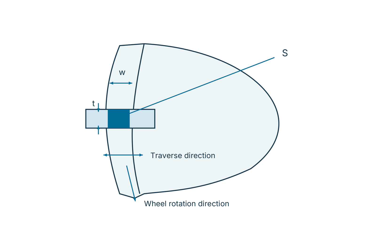
Contact area S depends on layer width w and contact length t. Force also depends on machine rigidity, workpiece support and the workpiece itself. At the same force, a smaller contact area raises contact pressure and can improve cutting. Wider layers can instead improve tool life. Selection balances removal performance and life against machine rigidity.
Machine, mounting, truing and dressing
A rigid, low-vibration machine with sufficient power maintains peripheral speed and infeed. Table or spindle vibration can cause chatter marks and heavy wear. Insufficient power favours speed loss and inefficient machining.
Correct mounting avoids workpiece marks, machine vibration, increased noise and shortened life. For the wheels described, the catalogue specifies less than 0.02 mm side runout for cup/dish wheels and less than 0.02 mm peripheral runout for straight wheels. Mounting takes place with the machine stopped: initially fasten the wheel lightly on its flange, check runout with an indicator, adjust in a controlled way where the fit permits, then secure the wheel and recheck. Adjustment requires clearance between bore and flange; without clearance, another runout-correction method is needed. The older catalogue describes light tapping at the periphery. In practice, use only the adjustment method approved for the particular wheel, such as a suitable wood or rubber block; mounting instructions from the manufacturer remain decisive.
Truing corrects runout and contour by removing grains and bond. Dressing then establishes a free-cutting layer by recessing the bond and exposing diamond. The catalogue recommends relatively hard truing tools about two grit grades coarser. The selection distinguishes C and WA designations; WA does not denote silicon carbide.
The four described methods are a brake-controlled truing device, abrasive stick, mild steel and a separate grinding unit. Their application features follow in the next section.
| Diamond-wheel grit | Truing tool |
|---|---|
| #80 or coarser | C46-M |
| #100–#200 | C60-M |
| #230–#325 | C80-M |
| #400 or finer | WA200-G |
Preparing diamond wheels and assessing economy
A brake-controlled device provides fast, simple and stable truing with the wheel remaining on the machine. A fixed abrasive stick can also correct the form, while possible rounding of the wheel edge should be considered. Mild steel provides a simple method without a special truing device, but requires abundant coolant to avoid thermal damage to the diamond wheel. A separate grinding unit machines the removed diamond wheel with a silicon-carbide wheel; runout must be checked again after remounting.
Dressing should mainly remove bond and expose diamond. The catalogue recommends sticks about two grit grades finer; the selection is listed in the table. Dressing uses suitable guidance and the equipment intended for the machine and tool. Coolant is specified; for dry operation, the source describes a wetted stick, whereas it recommends dry dressing with a lapping stick. Actual selection depends on stick and wheel specification.
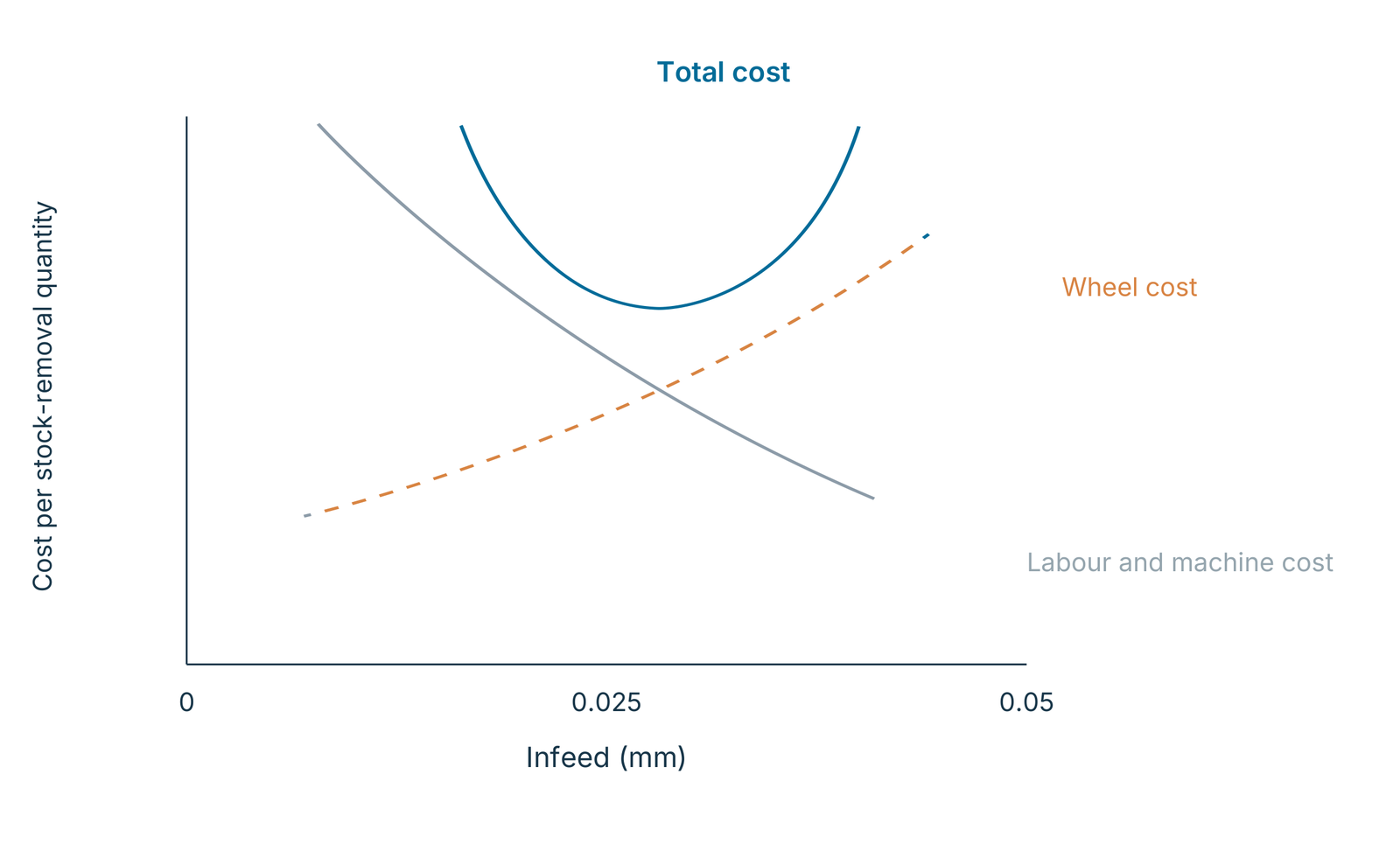
Economy consists of wheel cost plus other processing costs, particularly labour and machine cost. Tool life alone therefore does not describe the full benefit. The cost diagram shows the trade-off: wheel cost increases with infeed, while labour and machine cost per stock-removal quantity can fall. Their sum has a minimum in the illustrated scheme. Axis values of 0.025 and 0.05 mm illustrate this relationship and do not specify a universal optimum infeed.
| Diamond-wheel grit | Dressing stick |
|---|---|
| #80 or coarser | WA120-G |
| #100–#200 | WA200-G |
| #230–#325 | Lapping stick |
| #400 or finer | Lapping stick |
Diamond: peripheral speed, coolant and infeed
Peripheral speed influences life, removal and finish. It depends on wheel diameter and spindle speed. The stated ranges are catalogue recommendations for the named bonds; allowable tool and machine speed remains decisive.
Dry regrinding can permit direct observation of the contact area. However, a large contact area increases heat, loading and bond wear; wet grinding can reduce thermal loading. Coolant is directed into wheel/workpiece contact. Good lubrication and adequate supply pressure are particularly relevant in heavy removal or creep-feed grinding.
Infeed affects machining efficiency, but excessive increases can shorten tool life. The table gives recommended depths of cut by grit. For form grinding, the source describes balancing greater depth of cut with reduced feed to avoid profile deviation.
Finish depends on process, material and grit. Separate roughing and finishing allows high removal followed by a fine surface. The grit lists provide separate selections rather than a fixed pairing of each row. Spark-out can further improve finish.
| Bond | Wet (m/min) | Dry (m/min) |
|---|---|---|
| Resin | 1400–1600 | 900–1200 |
| Metal | 1000–1800 | 600–900 |
| Grit | Depth of cut |
|---|---|
| #100–#120 | 0.02–0.03 mm |
| #140–#200 | 0.01–0.02 mm |
| #230 or finer | ≤0.01 mm |
| Process stage | Grit selection |
|---|---|
| Roughing | #100, #120, #140 |
| Finishing | #270, #325, #400, #600 |
CBN: hardness, material mapping and grit
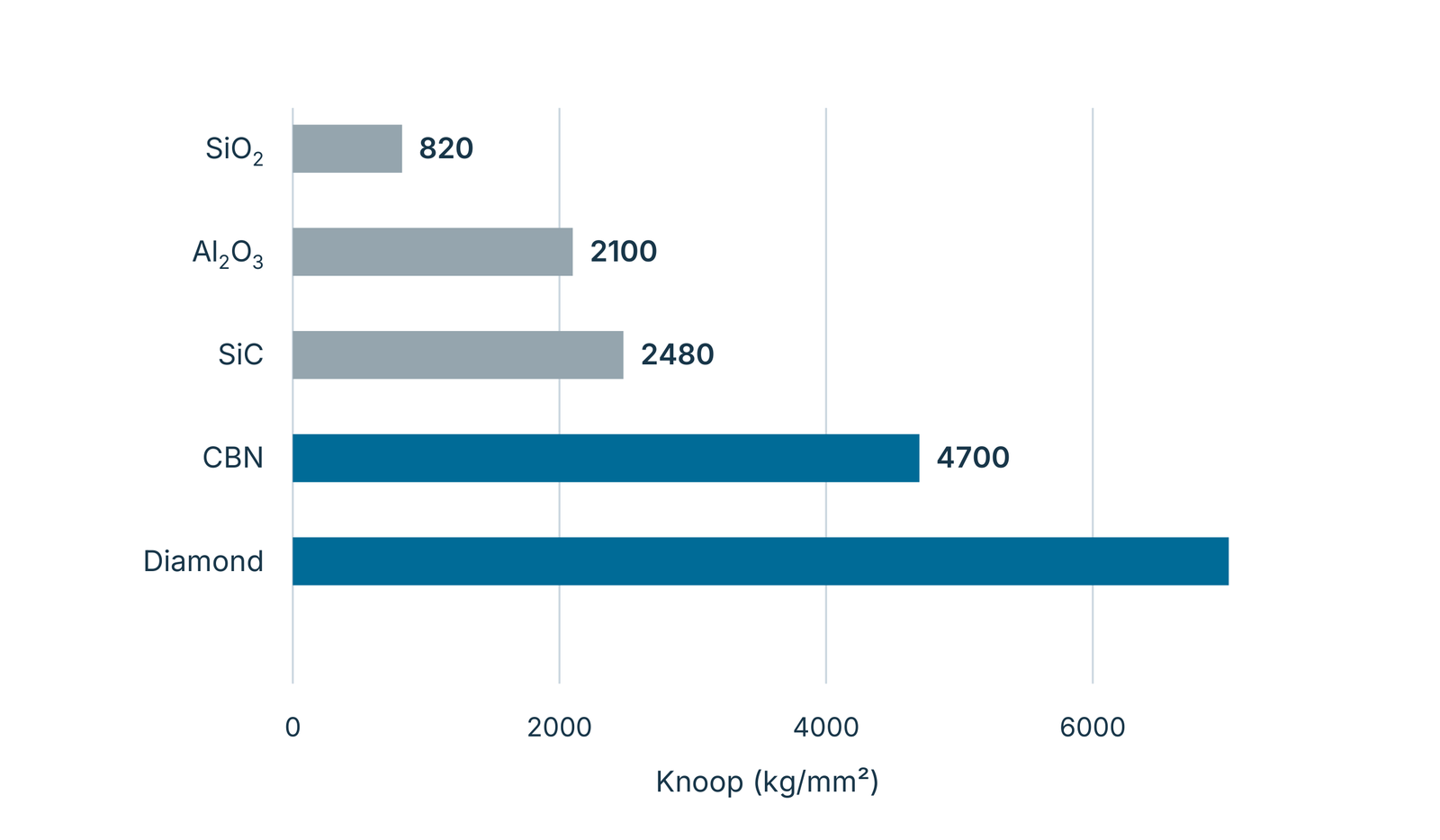
CBN is cubic boron nitride, a superabrasive for grinding steel. It is synthesised from boron-nitride feedstock at high pressure and temperature. CBN is harder than conventional abrasives such as aluminium oxide and silicon carbide; the Knoop comparison includes the material values stated in the catalogue.
Diamond has high hardness but can wear in contact with steel through chemical interaction with iron. The source gives 600–700°C as an indicative oxidation range in air and 1370°C as a CBN stability comparison value. These describe abrasive behaviour under respective conditions, not an allowable temperature for an entire grinding wheel. CBN combines high thermal resistance with low chemical affinity for iron, making it particularly suitable for appropriate ferrous materials.
Metal-coated CBN is mainly used in resin bonds; uncoated grains are used in electroplated, metal-bond and vitrified tools. Concentration follows the table explained earlier. The grit table retains both sieve sizes and G micron-grit designations.
| Nominal grit (mesh) | Sieve range / micron code | Catalogue designation, “FEPA” column |
|---|---|---|
| 60 | 60/80 | B252 |
| 80 | 80/100 | B181 |
| 100 | 100/120 | B151 |
| 120 | 120/140 | B126 |
| 140 | 140/170 | B107 |
| 170 | 170/200 | B91 |
| 200 | 200/230 | B76 |
| 230 | 230/270 | B64 |
| 270 | 270/325 | B54 |
| 325 | 325/400 | B46 |
| 400 | G45 | — |
| 800 | G30 | — |
| 1000 | G15 | — |
| 1500 | G9 | — |
| 2000 | G6 | — |
| 3000 | G3 | — |
| 5000 | G1 | — |
CBN: bond, speed and coolant
Resin-bond CBN wheels are used for surface, cylindrical, creep-feed, centreless, double-disc and internal grinding. CBN can work economically on suitable ferrous materials harder than HRC 50. Metal bonds are made by sintering metal powder with CBN and are intended for honing or cutting hardened steel and high removal in medium-hard steel. Porous vitrified bonds facilitate truing and dressing and support high-precision forms. The overview separates CBN and diamond applications.
Peripheral speed influences tool life, removal and finish. For resin-bond CBN, the source gives 1750–1850 m/min wet and 900–1200 m/min dry. It additionally describes an increase to 13,000 ft/min with sufficiently effective coolant supply. This is a catalogue process indication rather than a universal speed approval: tool and machine limits determine allowable speed.
Straight, water-immiscible oil provides strong lubrication and can benefit tough materials such as stainless steel, Inconel and Waspaloy and heavy-duty machining; its cooling effect is lower than that of water-based systems. The catalogue divides water-based fluids into emulsion, translucent soluble fluid and clear chemical fluid. Emulsion appears milky and combines lubrication with better cooling than oil. For the described emulsion application, the source specifies concentration above 5%; actual concentration depends on product and process. Translucent fluids offer stronger cooling but lower lubrication than emulsions and may suffice for general grinding. Clear chemical fluids offer strong cooling with lower lubrication; a suitable process does not automatically require changing fluid systems.
| Abrasive | Vitrified-bond application |
|---|---|
| CBN | Automotive parts: CV joints, gears, camshafts and crankshafts |
| CBN | Tool parts: endmills and thread dies |
| CBN | Bearings |
| CBN | Electronic parts: motors and sleeves |
| CBN | Hydraulic and pneumatic machines: compressors |
| CBN | Fuel pumps: injection nozzles |
| Diamond | Cutting tools: ceramic and PCD/PCBN inserts |
| Diamond | Surface grinding: silicon and cemented-carbide wafers |
| Diamond | Double-disc grinding: rotor gears |
| Diamond | Honing stones |
| Resin-bond CBN | Recommended peripheral speed |
|---|---|
| Wet | 1750–1850 m/min |
| Dry | 900–1200 m/min |

Surface roughness: historical reference comparison
The comparison retains every catalogue value for Rmax, Ra, RMS and Rz. It provides historical orientation rather than an exact conversion between roughness parameters. Different parameters describe different properties of the surface profile.
The printed RMS column in µin is also not mathematically identical to the RMS column in µm. Exact unit conversion is: 1 µin = 0.0254 µm. Required roughness should therefore be specified with parameter, unit and measurement conditions.
| Rmax (µm) | Ra (µm) | RMS (µm) | Rz (µm) | RMS (µin), source value |
|---|---|---|---|---|
| 0.1 | 0.02 | 0.02 | 0.1 | 1 |
| 0.2 | 0.03 | 0.04 | 0.2 | 2 |
| 0.3 | 0.05 | 0.06 | 0.3 | 3 |
| 0.4 | 0.07 | 0.08 | 0.4 | 4 |
| 0.5 | 0.09 | 0.10 | 0.5 | 5 |
| 0.6 | 0.10 | 0.11 | 0.5 | 6 |
| 0.7 | 0.12 | 0.13 | 0.6 | 7 |
| 0.8 | 0.14 | 0.15 | 0.7 | 8 |
| 0.9 | 0.15 | 0.17 | 0.8 | 9 |
| 1.0 | 0.17 | 0.19 | 0.9 | 10 |
| 1.2 | 0.20 | 0.23 | 1.1 | 12 |
| 1.4 | 0.24 | 0.27 | 1.3 | 14 |
| 1.6 | 0.27 | 0.30 | 1.4 | 16 |
| 1.8 | 0.31 | 0.34 | 1.6 | 18 |
| 2.0 | 0.34 | 0.38 | 1.8 | 20 |
| 2.4 | 0.41 | 0.46 | 2.2 | 24 |
| 2.8 | 0.48 | 0.53 | 2.5 | 28 |
| 3.2 | 0.54 | 0.61 | 2.9 | 32 |
| 3.6 | 0.61 | 0.68 | 3.2 | 36 |
| 4.0 | 0.68 | 0.76 | 3.6 | 40 |
| 4.5 | 0.77 | 0.86 | 4.1 | 45 |
| 5.0 | 0.85 | 0.96 | 4.5 | 50 |
| 5.5 | 0.94 | 1.05 | 5.0 | 55 |
| 6.0 | 1.02 | 1.14 | 5.4 | 60 |
| 7.0 | 1.19 | 1.33 | 6.3 | 70 |
| 8.0 | 1.36 | 1.52 | 7.2 | 80 |
| 9.0 | 1.53 | 1.71 | 8.1 | 90 |
| 10.0 | 1.70 | 1.90 | 9.0 | 100 |
International cooperation and locations
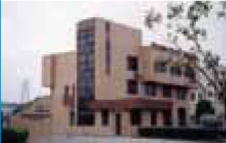
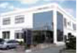
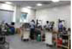
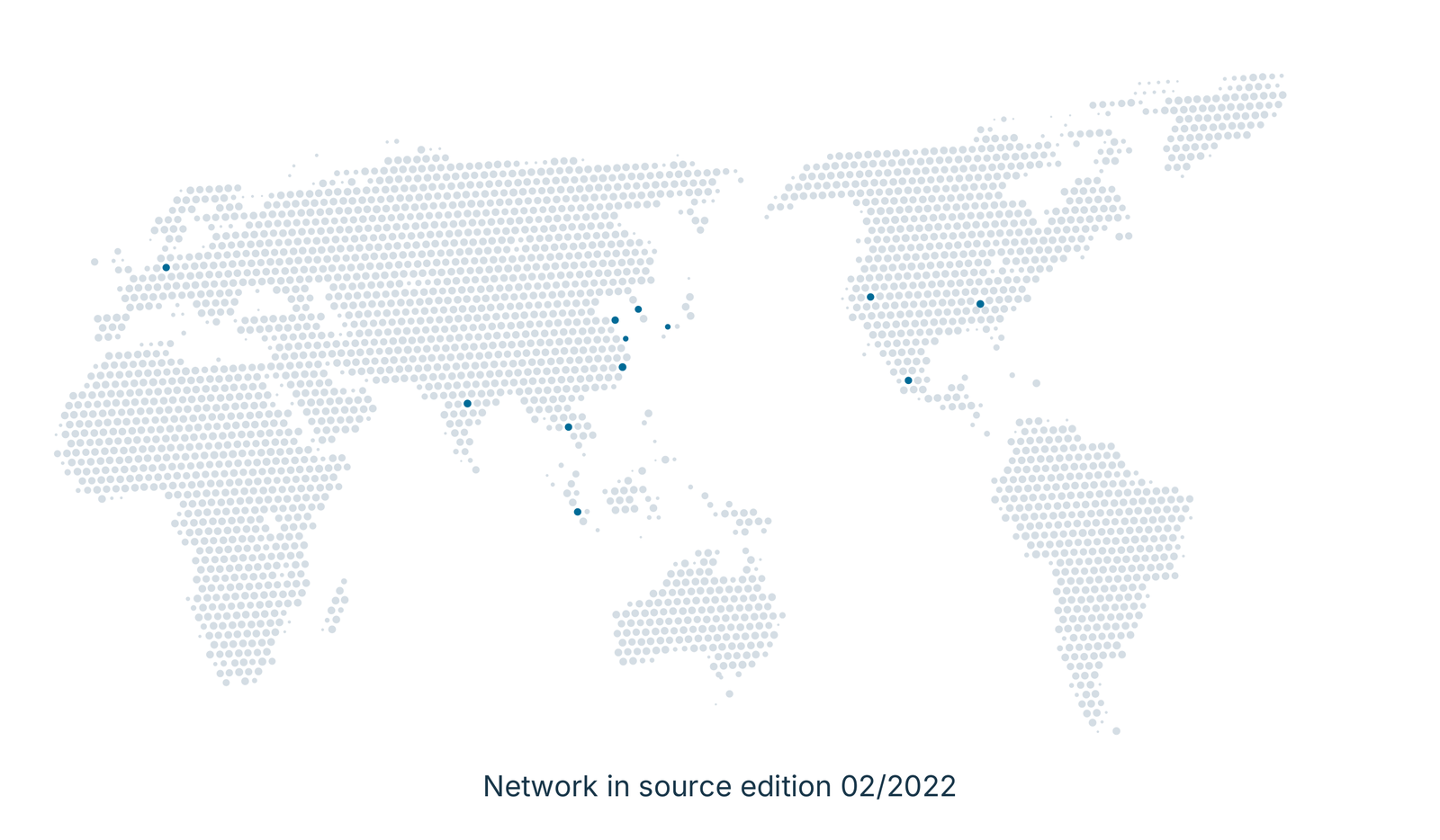
Since 1975, EHWA has developed long-term partnerships with customers across industries. Product development and service support this cooperation. The location photographs show the international network documented in the source catalogue, including Korean locations and offices, plants and affiliated businesses in other countries.
The following overview belongs to source edition 02/2022 and documents its information. For technical coordination in Europe, contact EHWA Europe at info@ehwadia.de or +49 6173 997780.
| Region | Locations in the source edition |
|---|---|
| Korea | Osan, Osan 2, Dongtan, Pyeongtaek, Seocheon, Cheongju |
| China | Fujian, Weihai, Shanghai |
| Vietnam | Bac Ninh, Hai Duong |
| Further countries | Indonesia, Germany, Japan, California/USA (affiliate), Alabama/USA, Italy, Thailand, India, Mexico |

















Manufacturer and source edition of the main programme
The main catalogue was issued by EHWA DIAMOND INDUSTRIAL CO., LTD. and carries the print marking 02/2022. The back cover names ISO 9001 and ISO 14001 in the TÜV Management Service symbol used in that edition. This records the catalogue marking rather than providing evidence of a current certificate.
Manufacturer information from the source edition is listed in the table. EHWA Europe is your contact for enquiries about the European tooling programme. This newly typeset programme has editorial edition 2026-10-13.
| Item | Manufacturer contact in the source edition |
|---|---|
| Manufacturer | EHWA DIAMOND INDUSTRIAL CO., LTD. |
| Address | 374, Nambudae-ro, Osan-city, Gyeonggi-Do, 18145, Korea |
| Website | http://www.ehwadia.com |
| bkkim@ehwadia.co.kr | |
| Phone | +82 (31) 370-9220 |
| Fax | +82 (31) 370-9840 |
| Print marking | 02/2022 |
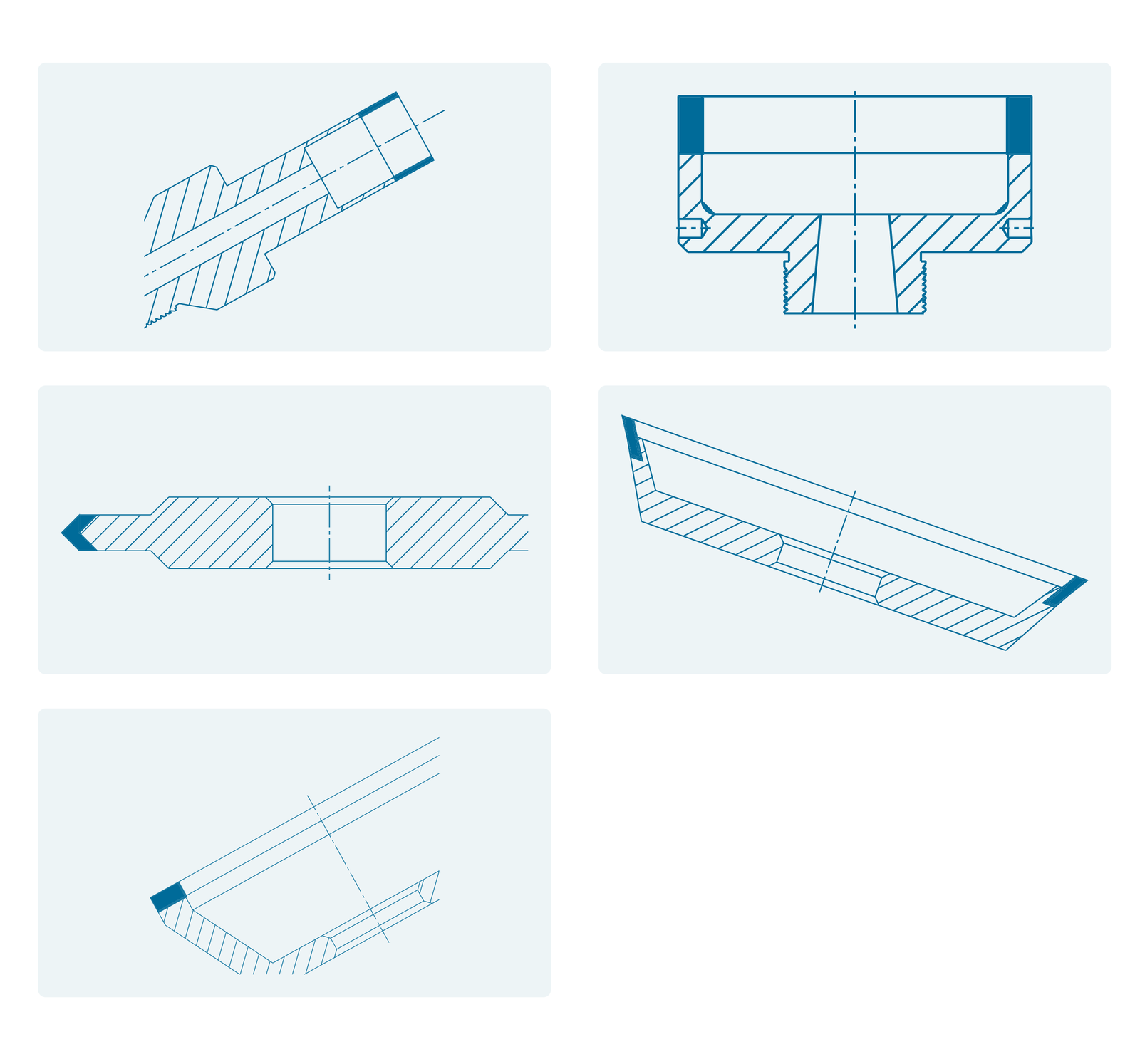
Tooling supplement: porous hybrid bond
Porous-hybrid-bond diamond wheels grind flutes in carbide drills and end mills, perform drill gashing and grind clearance angles. The bond supports high feed rates and high stock-removal rates. Further benefits include reduced residual stress and thermal damage, high dimensional stability, good surface and edge quality, long dressing intervals and low power consumption.
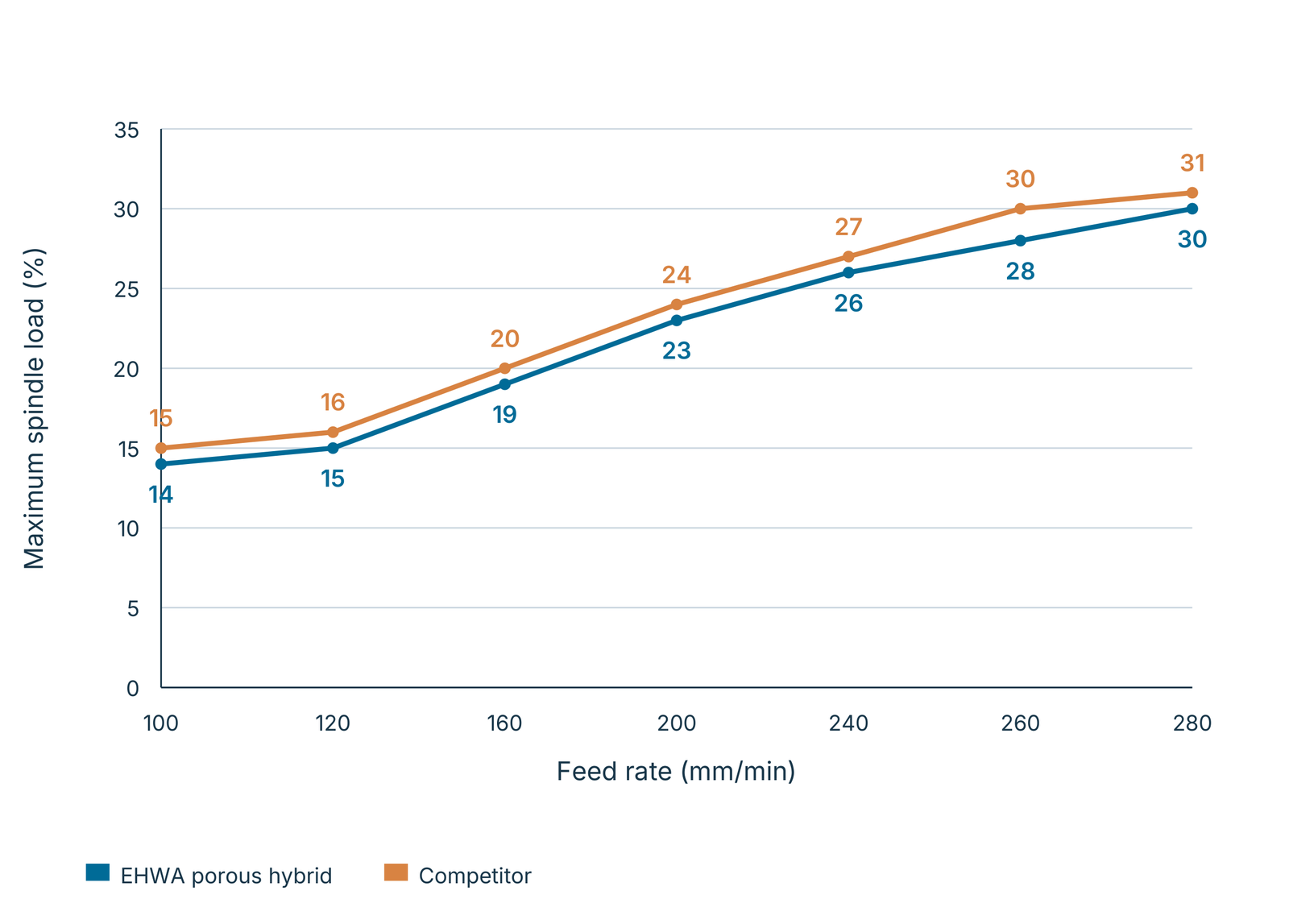
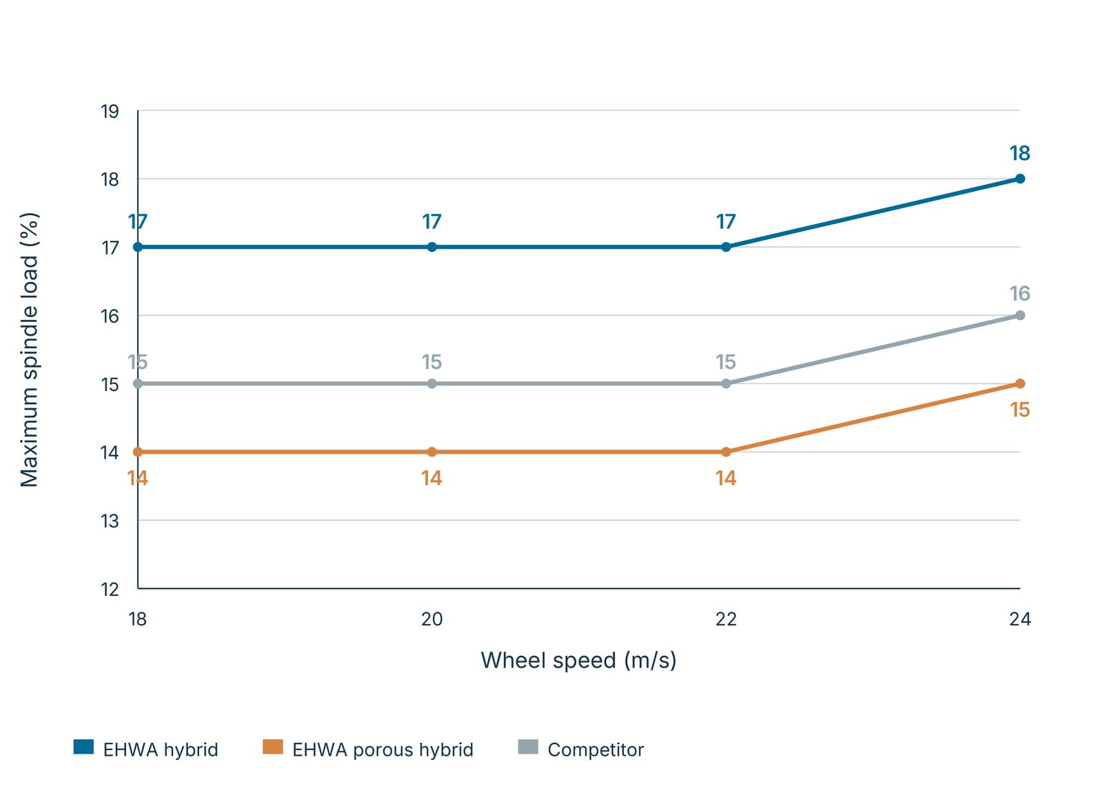
The test on an ANCA MX7 Linear uses D54 in a porous hybrid bond. The charts and tables retain the printed maximum spindle-load values. At every compared feed rate, the porous EHWA wheel has a lower load than the competitor. In the speed comparison, it also has a lower load than the EHWA hybrid variant. These are results of this test; additional engagement and workpiece conditions are not quantified in the sheet.
For cycle time, the main programme explains that higher permissible feed rates can enable shorter machining times. The supplement also says “Longer cycle time”, which is not clearly consistent with that explanation. This wording is not interpreted here as a measured time reduction or as a benefit of taking longer to machine a part.
| Feed rate (mm/min) | EHWA porous hybrid: load (%) | Competitor: load (%) |
|---|---|---|
| 100 | 14 | 15 |
| 120 | 15 | 16 |
| 160 | 19 | 20 |
| 200 | 23 | 24 |
| 240 | 26 | 27 |
| 260 | 28 | 30 |
| 280 | 30 | 31 |
| Wheel speed (m/s) | EHWA hybrid: load (%) | EHWA porous: load (%) | Competitor: load (%) |
|---|---|---|---|
| 18 | 17 | 14 | 15 |
| 20 | 17 | 14 | 15 |
| 22 | 17 | 14 | 15 |
| 24 | 18 | 15 | 16 |
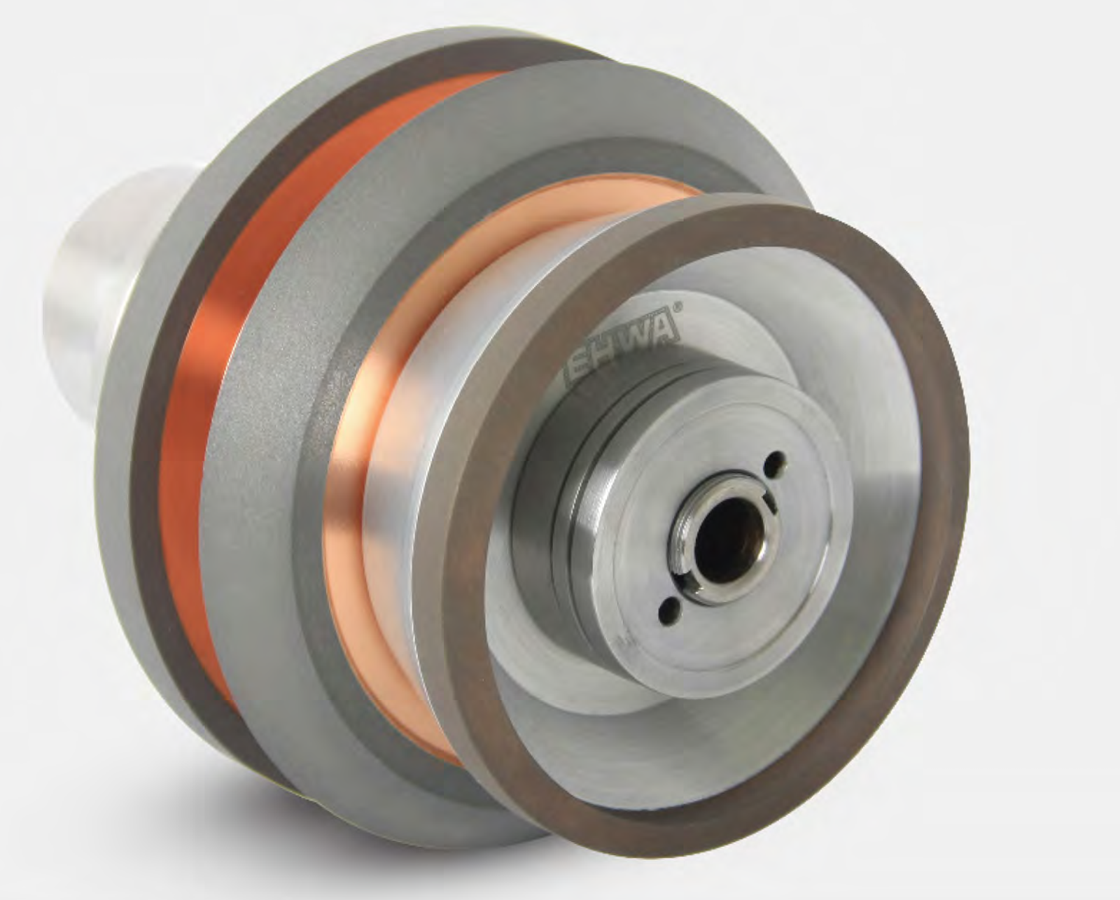
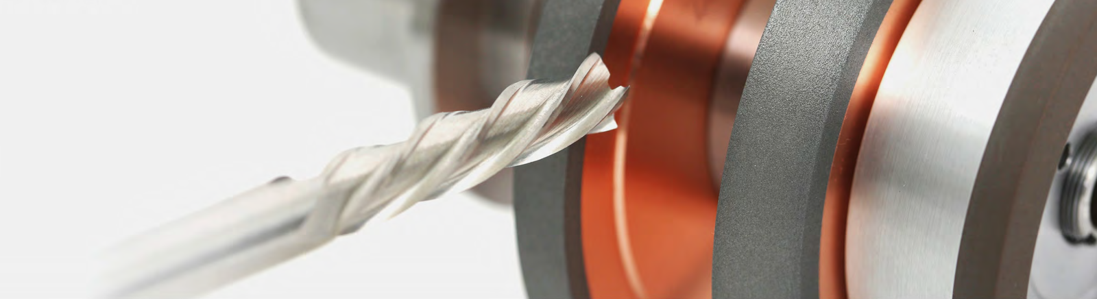
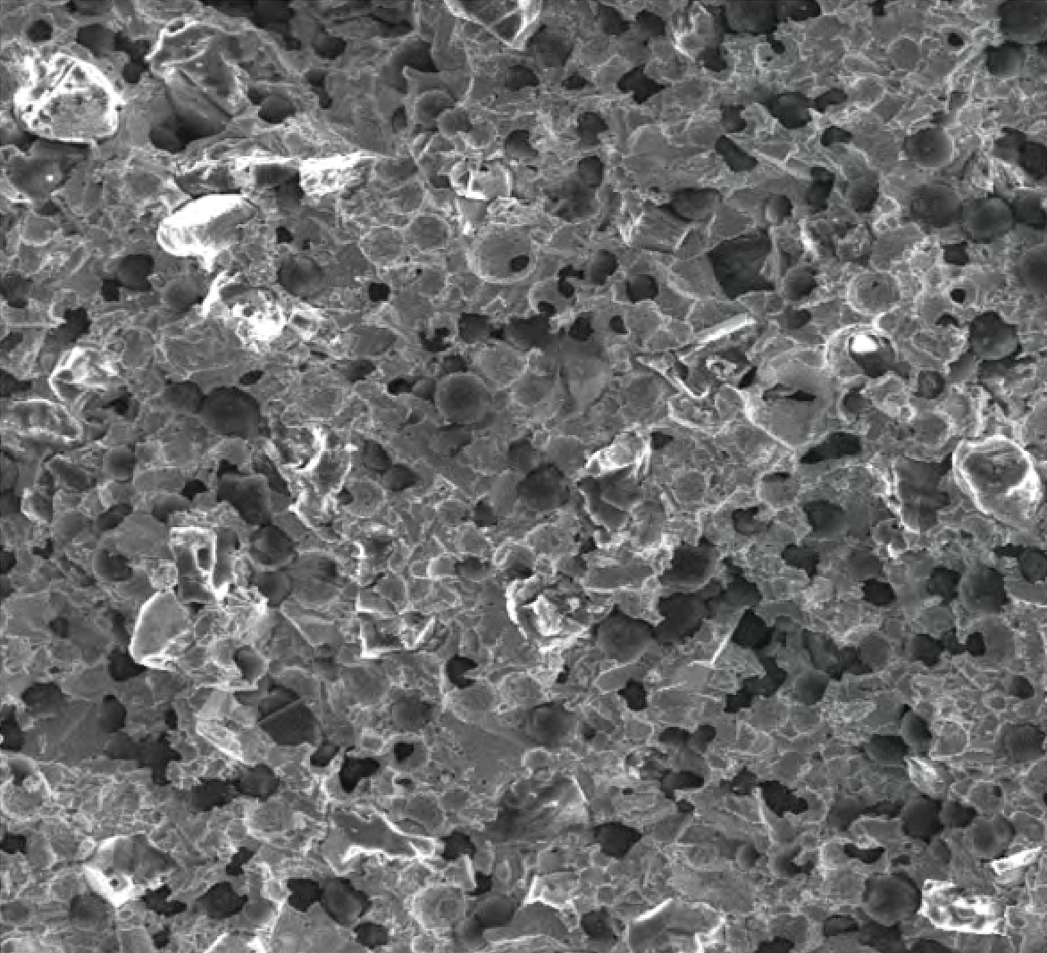
Tooling supplement: micro rotary tools
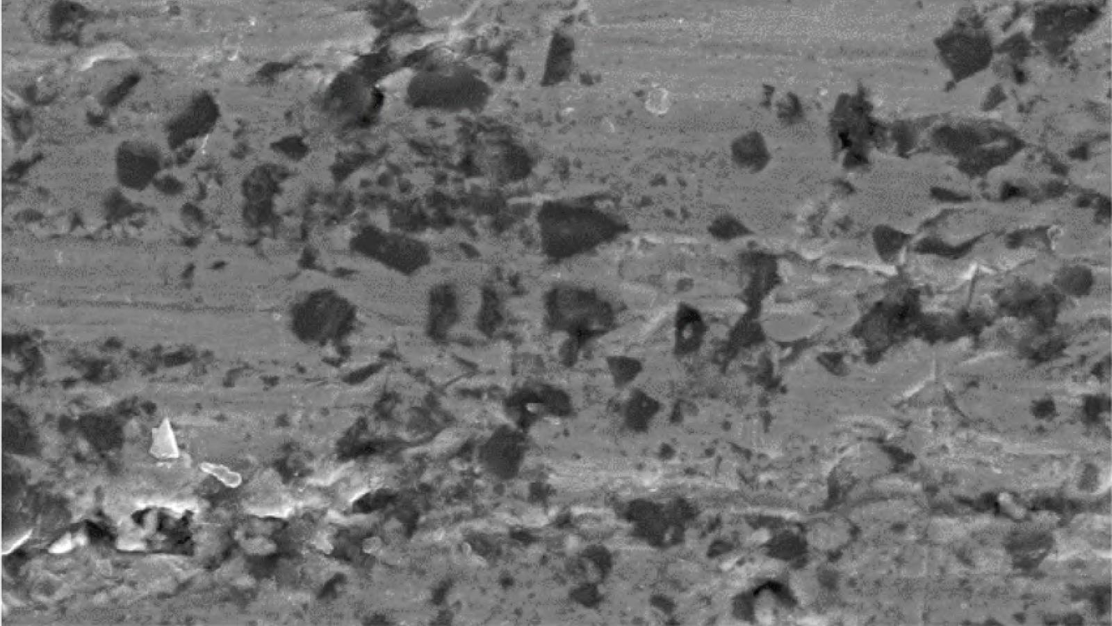
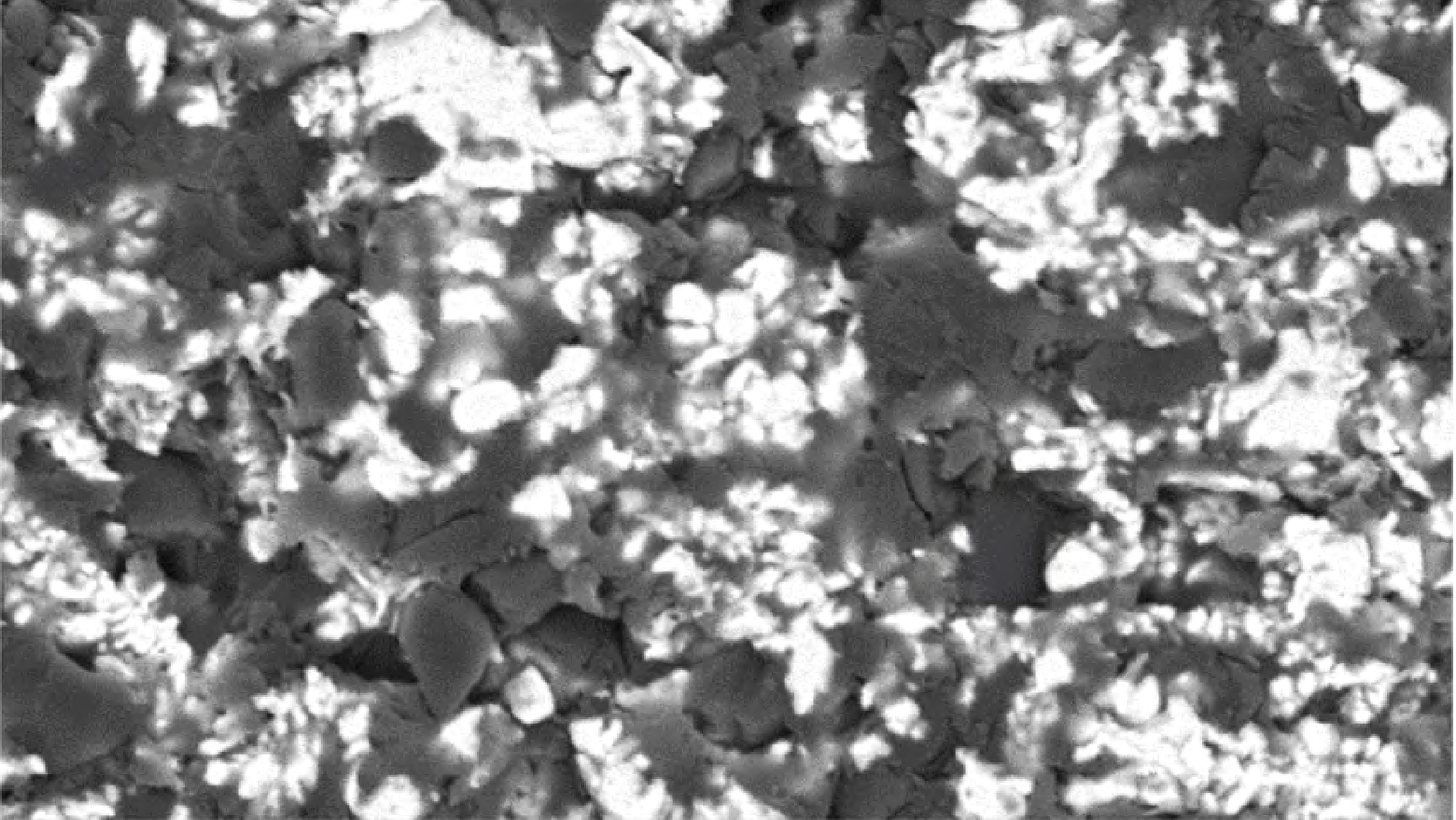
For micro drills, micro end mills and router bits, EHWA combines high productivity with low tooling costs. The described wheels offer high heat resistance, good surface and edge quality and precise dimensional edge stability. The micrographs show a hybrid bond and a high-performance polyimide bond as separate options.
EHWA lists ROLLOMATIC, ANCA and WALTER as machine examples. The cutting-tool images are marked at ×200 and ×50 magnification. They illustrate micro geometries; no extra dimensions are inferred from the images.
Tooling supplement: Mevious metal/vitrified hybrid
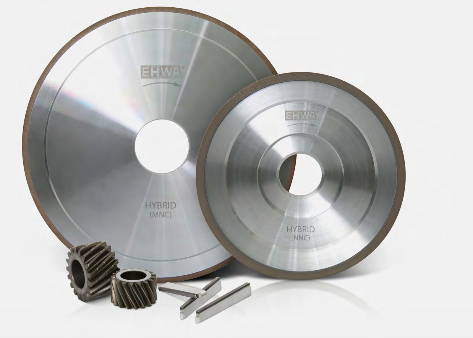
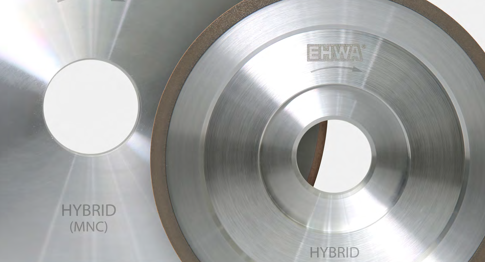
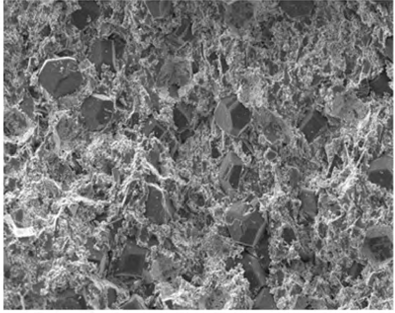
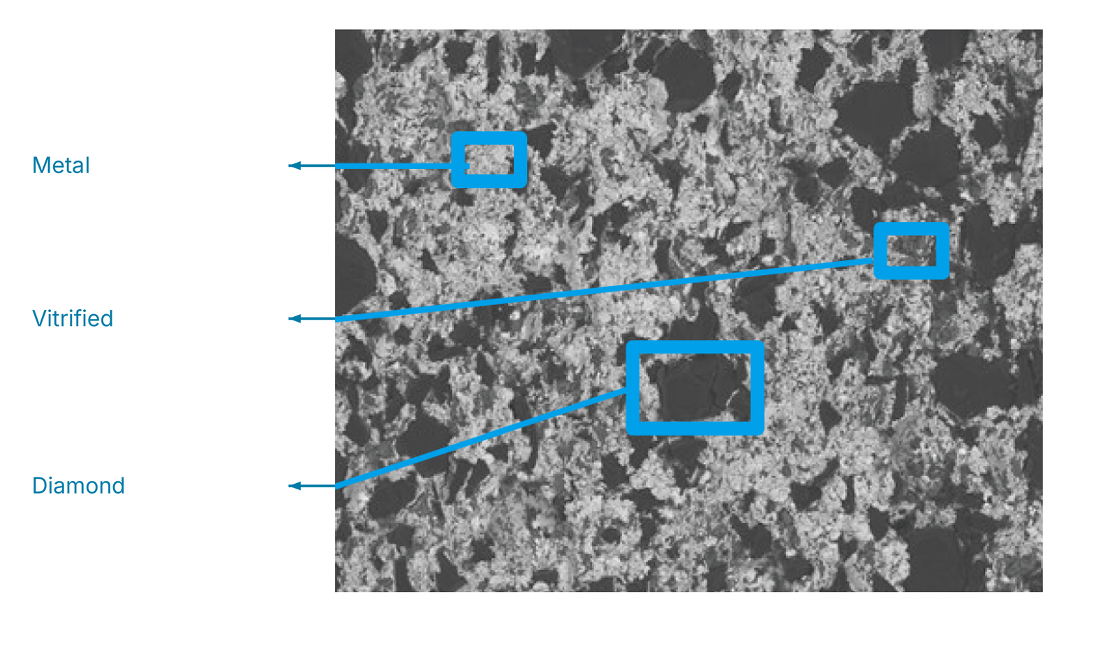
Mevious MNC combines the wear resistance of a metal bond with the grinding performance of a vitrified bond. This metal/vitrified hybrid is a separate bond family and is not equated with the polyimide/metal hybrid described earlier. Long tool life and good profile stability are central benefits.
Applications include carbide end mills and drills, alloy tools and honing stones for gears. The sheet lists MNC series MJ and MS, the following grit range and the wheel-size range.
In the relative catalogue comparison, tool life is 120% and the criterion labelled “Surface roughness” is 115%, each against 100% for the competitor. For the second criterion, the source supplies neither Ra/Rz, a physical unit nor an assessment direction. The 115% value is therefore a comparison index, not a promise of roughness being 15% higher or lower.
| Grit size | Wheel size | MNC bond |
|---|---|---|
| #60–#3000 | 40D–450D | MJ, MS |
| Comparison criterion | EHWA | Competitor |
|---|---|---|
| Tool life | 120% | 100% |
| “Surface roughness”: source index | 115% | 100% |


Tooling supplement: vitrified CBN wheels for bearing rings
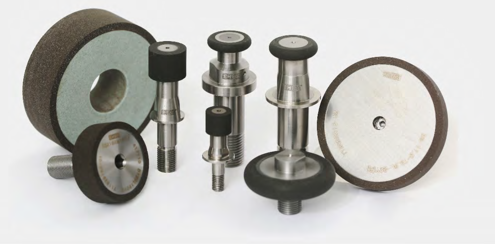
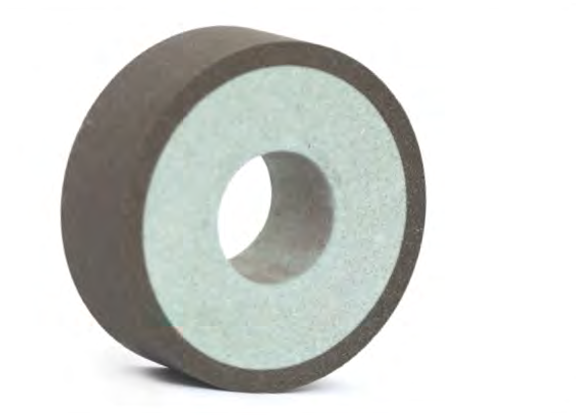
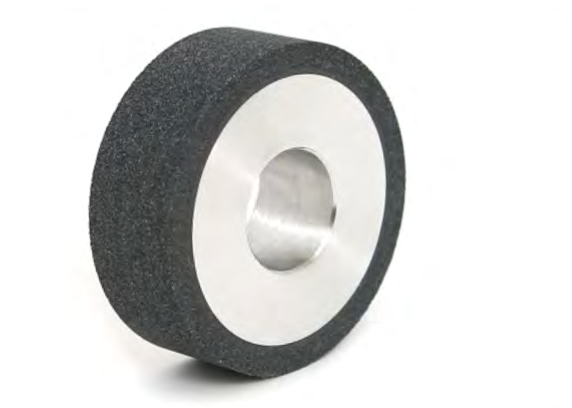
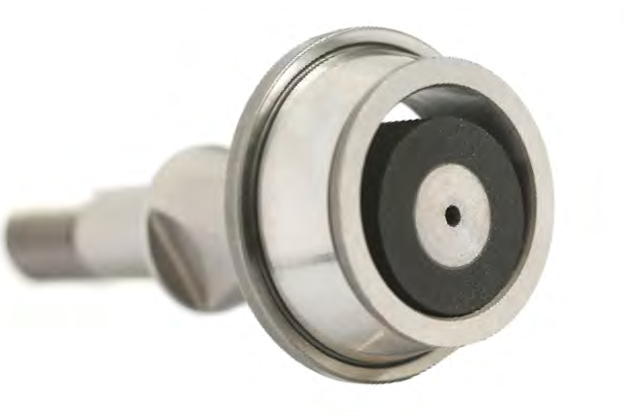
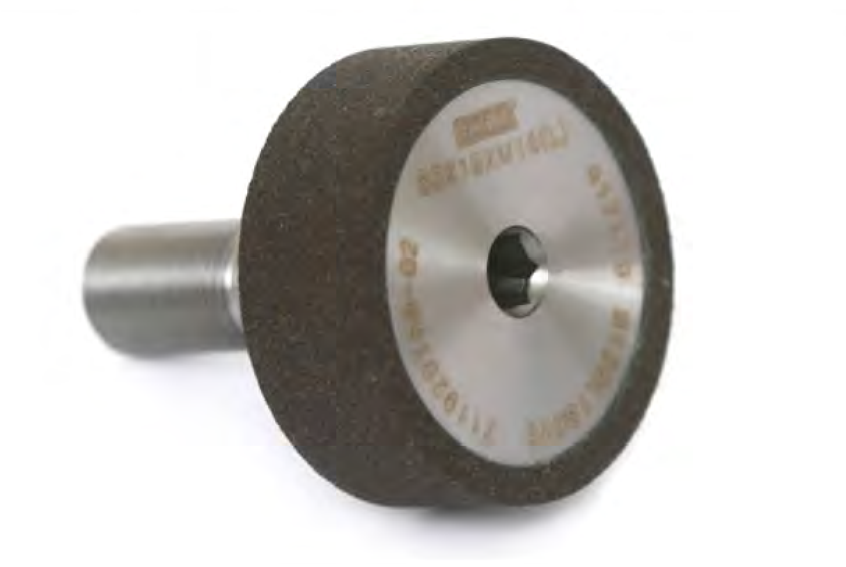
Vitrified CBN wheels grind the inner bore, inner-race track, outer-race track, lip and ring face. They support high removal rates and shorter cycle times with reduced grinding force. Further benefits include lower mechanical and thermal damage to the rings, precise surface finish and cylindricity and reduced dimensional deviation.
The supplement gives the same six process figures as the main programme. They describe this application range and are matched to the ring, wheel, dresser and machine. Four mounting arrangements are shown: ceramic core, steel core, steel quill and steel head.
| Parameter | Supplement value |
|---|---|
| Wheel speed | 30–80 m/s |
| Diameter removal | 0.1–0.35 mm D |
| Dressing amount | 5–30 µm |
| Dressing ratio | 0.3–0.6 |
| Dresser | Diamond rotary dresser |
| Coolant | Oil or emulsion |
Tooling supplement: injector bore and seat grinding
CBN mounted points grind the bore and sealing seat of fuel-injection components. Free-cutting behaviour, long dressing intervals and efficient tool utilization support consistent grinding performance. The precise wheel shape also includes the coolant hole and slots.
The standard figures match the ranges given in the main programme. Cylindrical and pointed tools for bore and seat grinding and the slot geometry are shown as different tool forms.
| Feature | Standard figure |
|---|---|
| Coolant hole | H 0.5–1.0 mm |
| Wheel size | D 1.5–20 mm |
| CBN grit size | 29–76 µm |
| Slot | 0.4–1.5 mm |

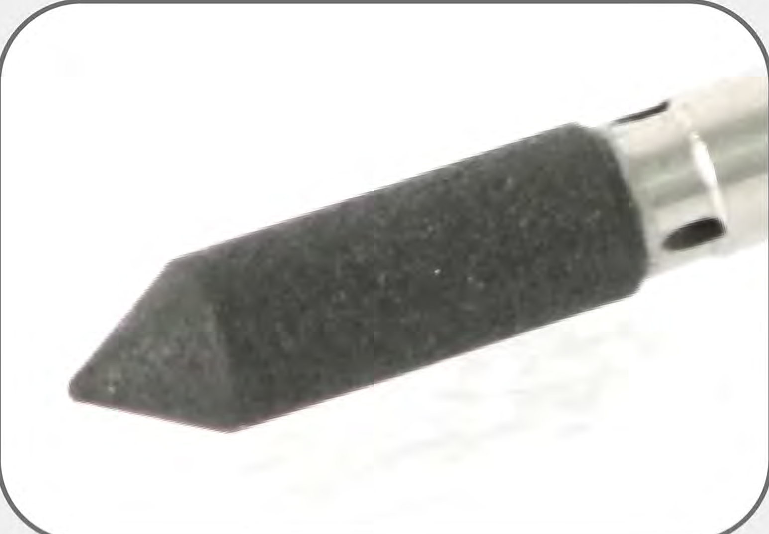
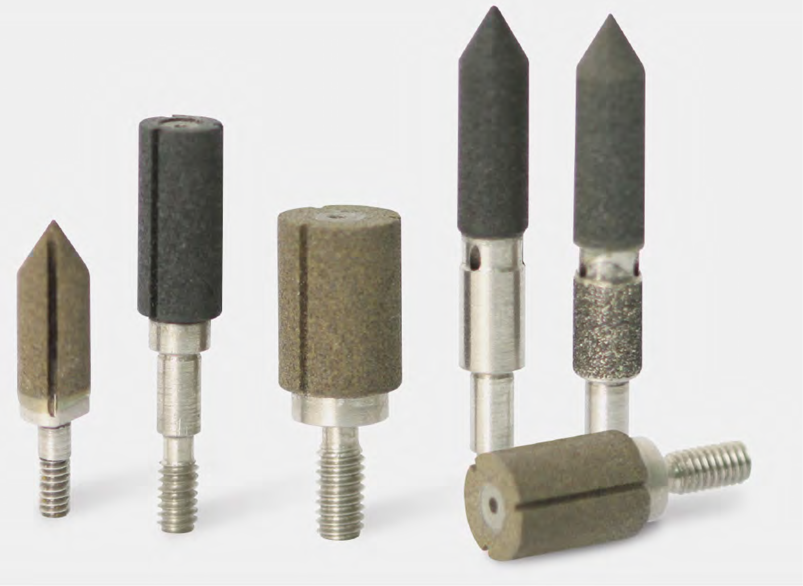

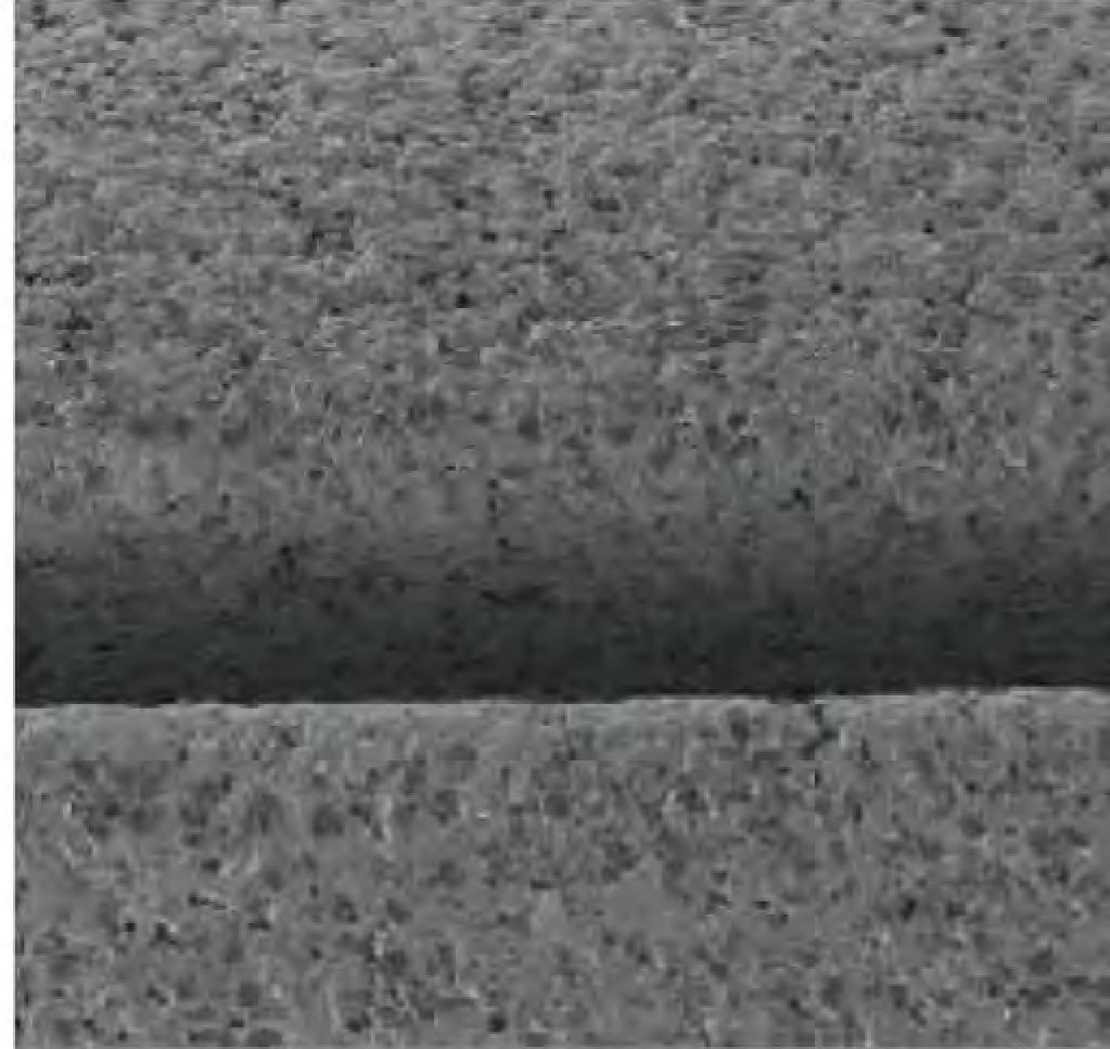
Tooling supplement: metal cup dressers
Metal cup dressers are used for bearing-ring internal grinding. They offer long life, precise dressing with low dimensional deviation after dressing and long dressing intervals. The sheet gives 20,000–30,000 dressing operations explicitly depending on grinding-wheel size.
The reference arrangements show vitrified wheels with a steel quill and a steel head. Two comparisons relate layer widths 2.5W and 1W to dressing performance and workpiece dimensional stability. No physical unit is given for the bar scales. The charts compare the illustrated variants on the original relative scales.

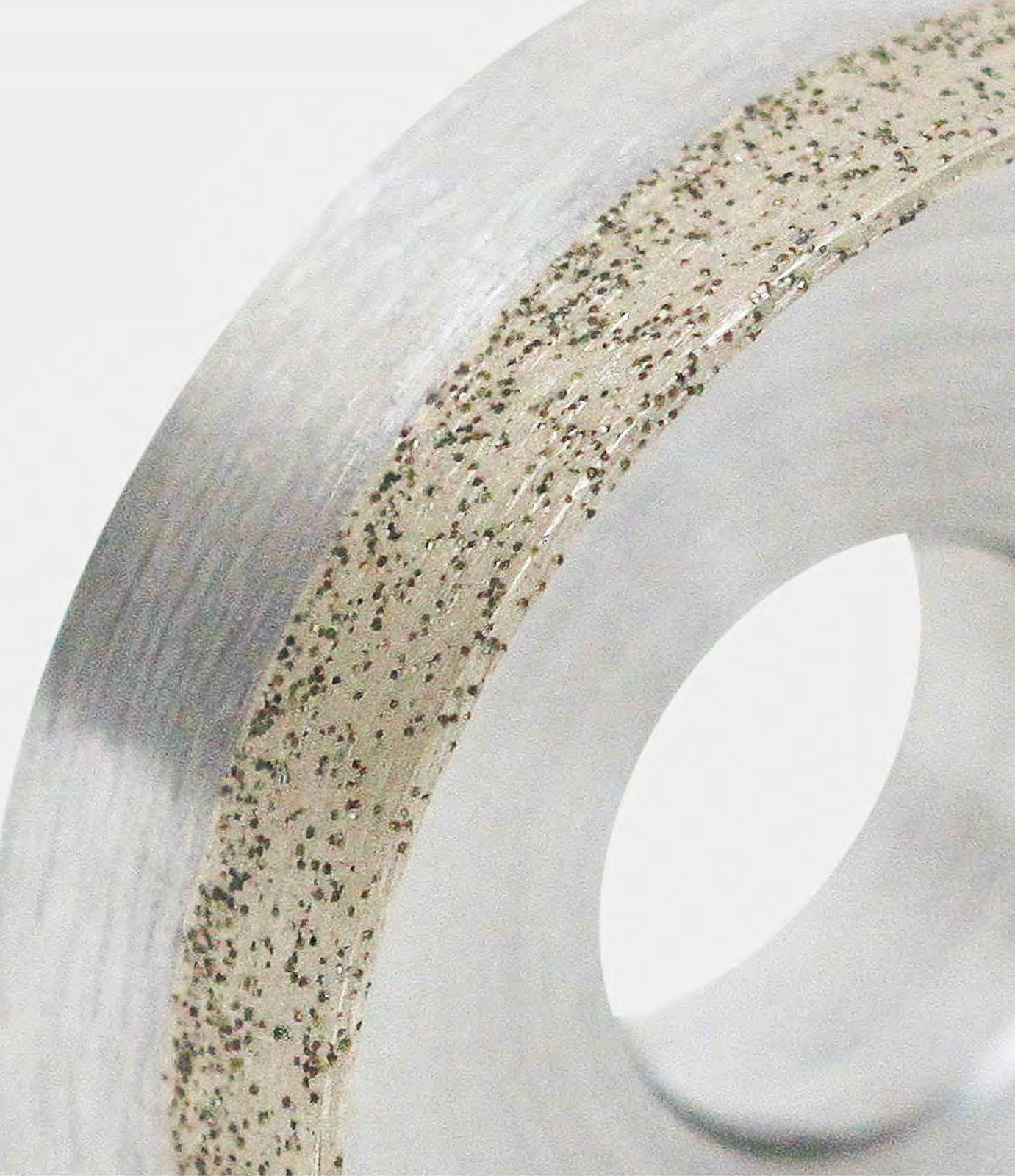
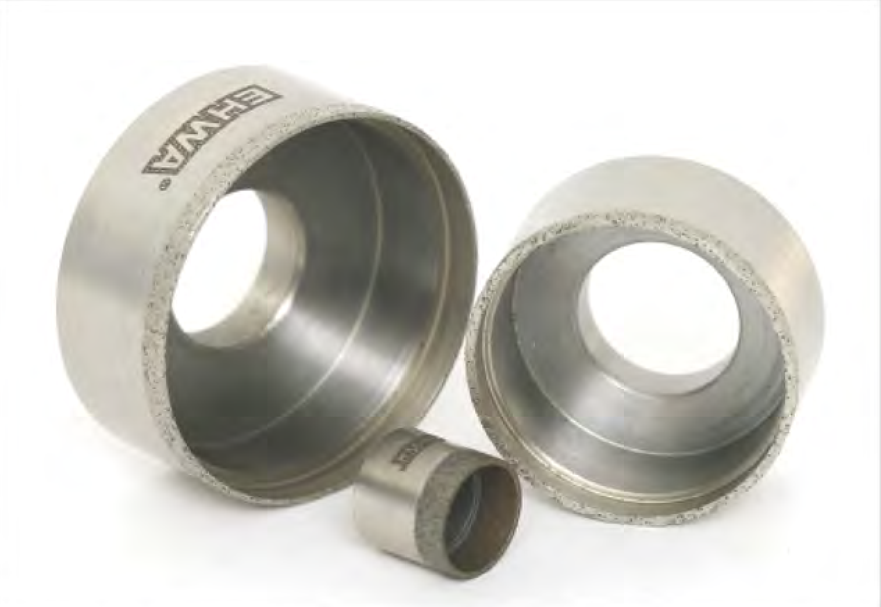
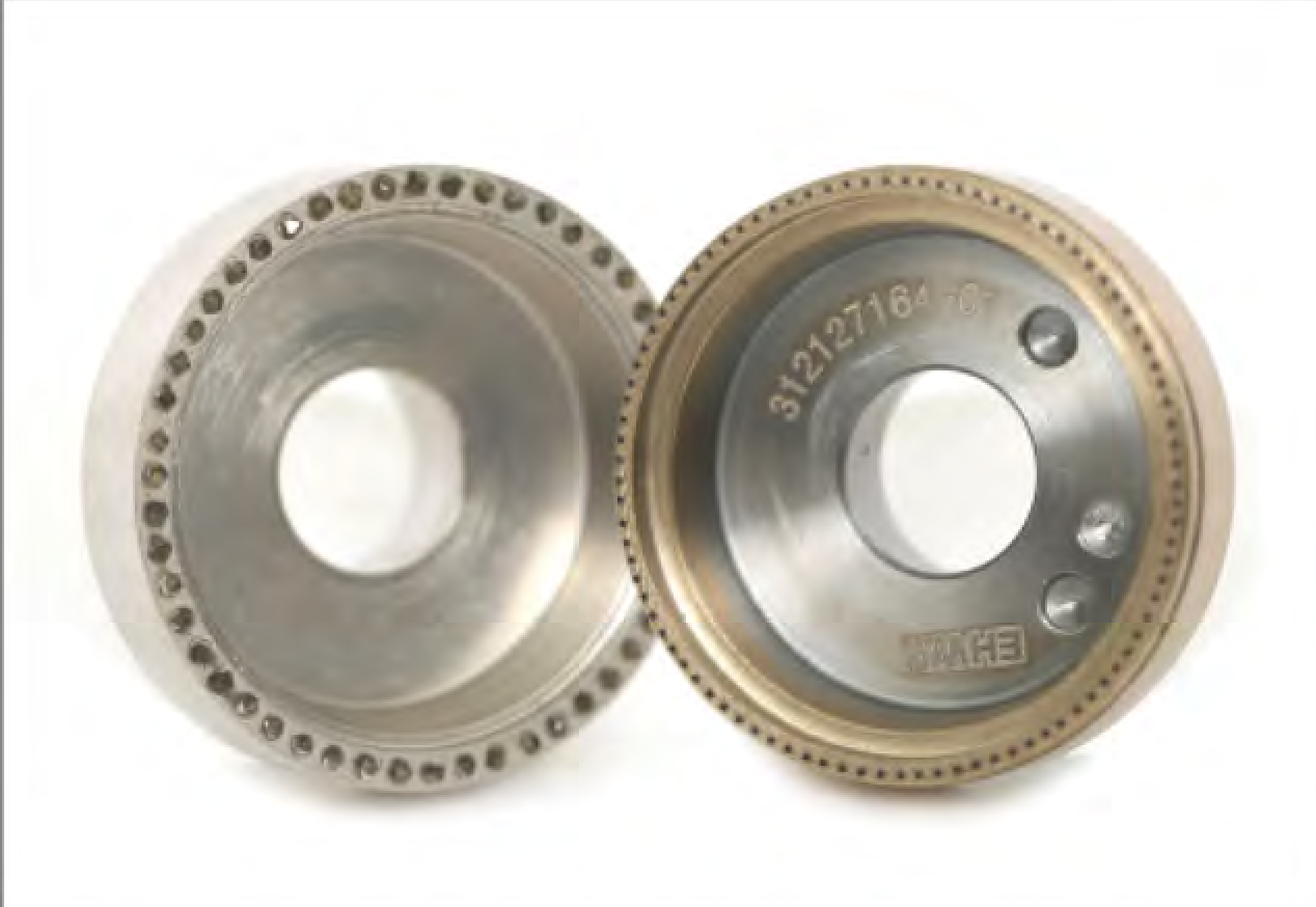


AMB supplement: peripheral insert grinding
EHWA hybrid-bond wheels grind the periphery of carbide, cermet and ceramic inserts. Benefits include higher feed rates, shorter cycle times, longer dressing intervals, precise edge dimensional stability and smaller edge chipping. WENDT, AGATHON and WAIDA are listed as machine examples.
This separate trial on a WENDT WAC 715 QUATTRO uses D40C100 in a hybrid bond at 21 m/s and reports a chipping size of 10 µm. It remains separate from the earlier main-programme trial, which publishes different specifications and conditions. The microstructure and edge images illustrate the bond and cutting edge; the measured value is the test value given below.
| Machine | Specification | Wheel speed | Chipping size |
|---|---|---|---|
| WENDT WAC 715 QUATTRO | D40C100 Hybrid bond | 21 m/s | 10 µm |
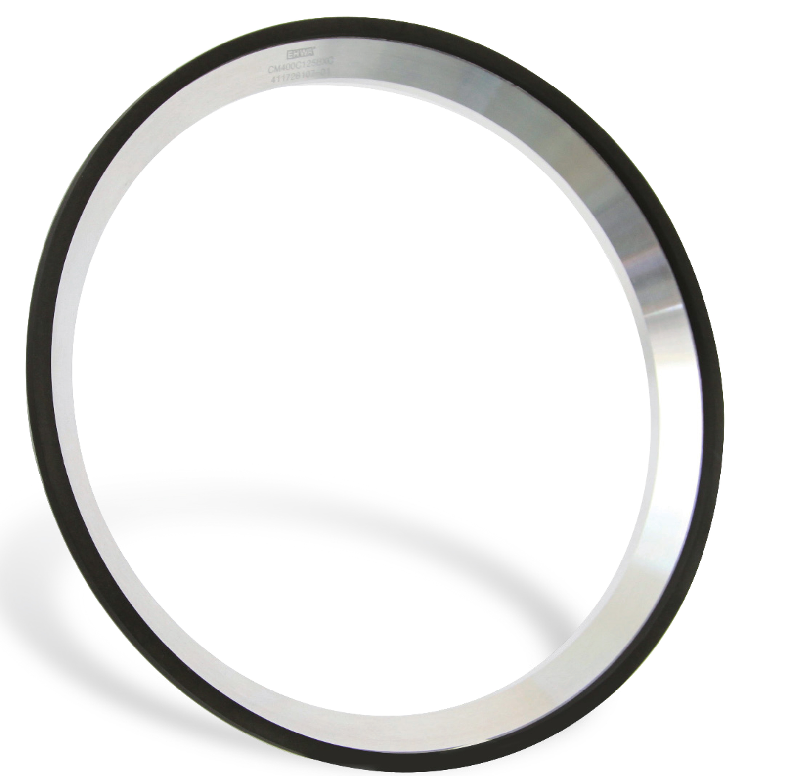
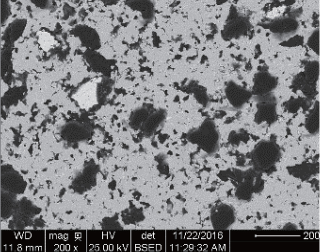
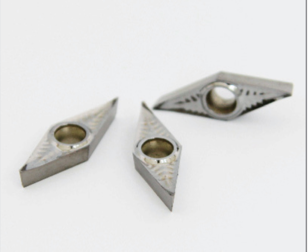
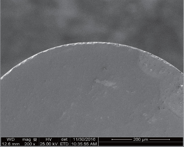
AMB supplement: porous hybrid for rotary tools
The AMB sheet presents porous hybrid bonds for flute grinding in carbide drills and end mills, drill gashing and clearance-angle grinding. It again lists high feed rates, high stock-removal rates, reduced residual stress and thermal damage, dimensional stability, surface and edge quality, long dressing intervals and low power consumption as benefits.
The two trials fully match the Tooling sheet presented earlier: ANCA MX7 Linear, D54 in a porous hybrid bond and the same 26 spindle-load values. The complete tables are therefore given once in that section; this AMB presentation retains both charts and the additional wheel-pack photograph. The same local explanation applies to its wording “Longer cycle time”; no new cycle time was measured or specified.
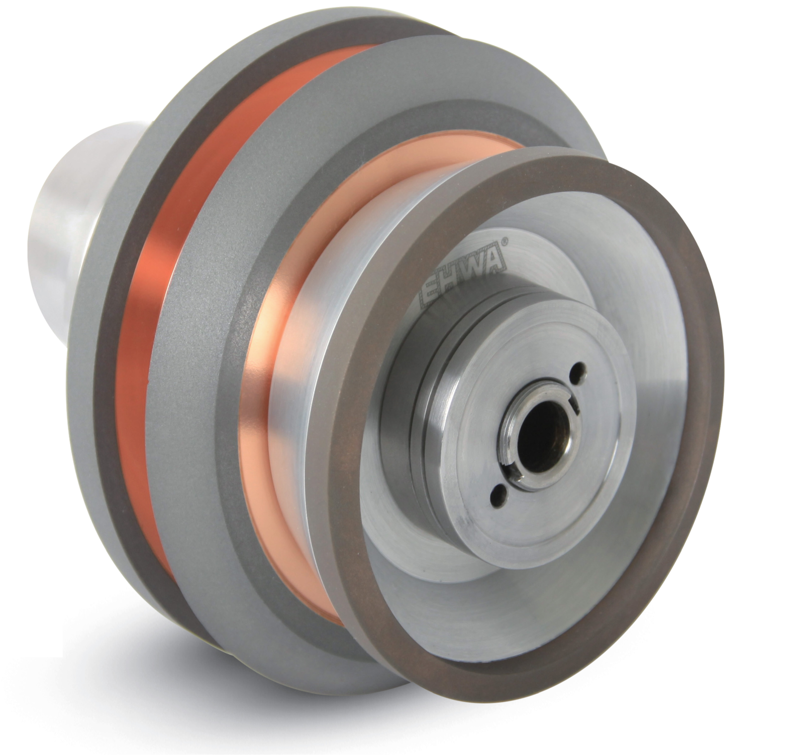

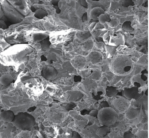
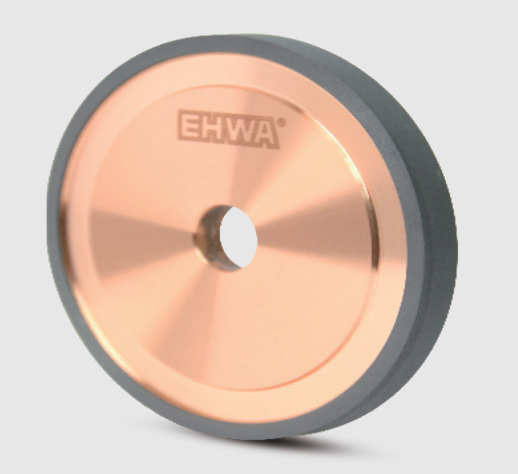
AMB supplement: rotary dressers for turbine blades
Workpiece-specific rotary dressers support precision turbine-blade manufacturing. The stated benefits are long tool life, tool precision and stable dressing performance during creep-feed grinding. Four contact arrangements show different approaches to the blade or counterprofile.
The dresser is designed for the actual workpiece contour. The schematics contain no dimension or angle values and do not define a new binding geometry. The dresser, blade component and aircraft engine remain as genuine application images.
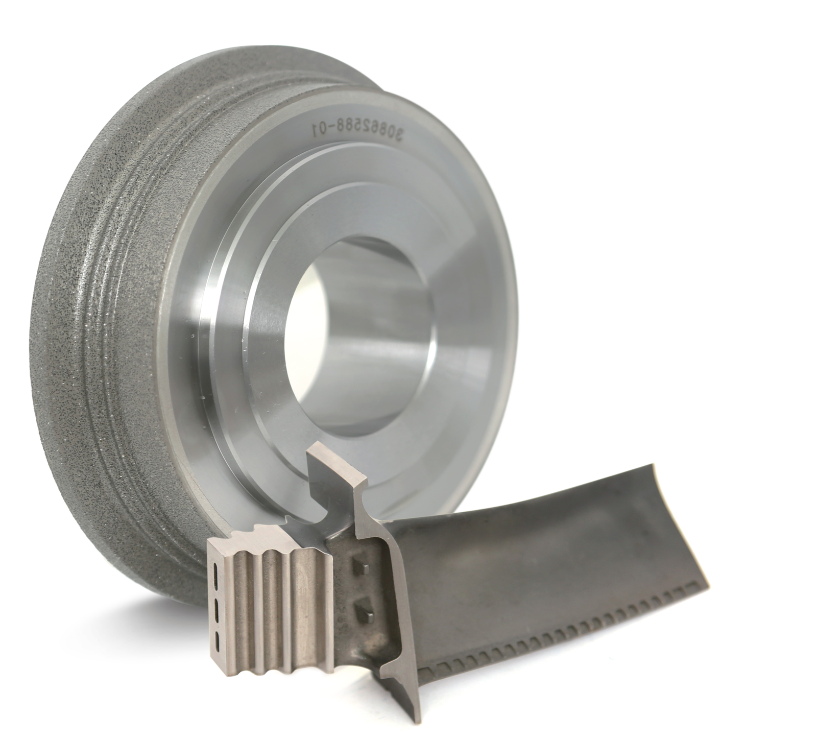

AMB supplement: precision dressing for gear grinding
EHWA develops precision dressers to suit each customer process. Grinding simulation during design supports uniform gear-dresser quality. The sheet refers to the hob cutter and a tool it calls the “worm wheel”; in generating grinding, this is the grinding worm.
The range includes Single Cone, Double, Single & Root, Single Taper Disk and Multi Ribbed. All five tools, corresponding dressers and contact profiles are shown separately. Single & Root includes an additional lower root contour. In Single Taper Disk, the two discs are separated by a gap continuing to the base. Selection follows the profile, machine and required dressing contact.
| Source designation | Profile contact |
|---|---|
| Single Cone | Single contact |
| Double | Two contacts on a shared body |
| Single & Root | Tall single profile and lower asymmetric root |
| Single Taper Disk | Two separate profiles with a through-gap |
| Multi Ribbed | Multiple ribs with a shared profile body |

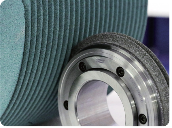
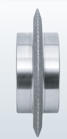
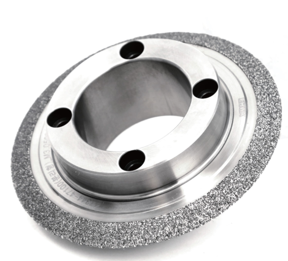
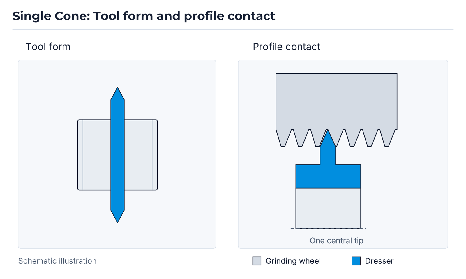
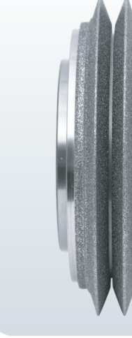
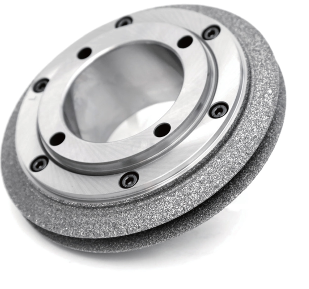


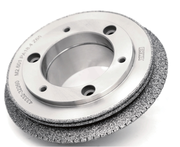
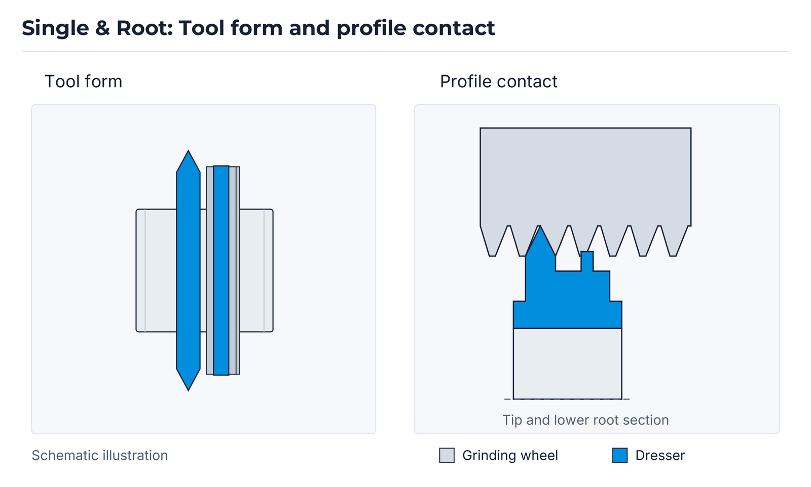
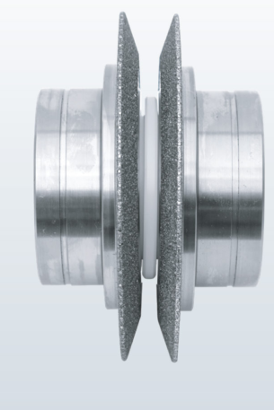
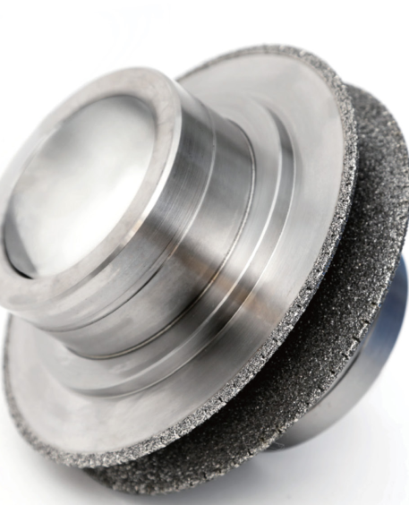
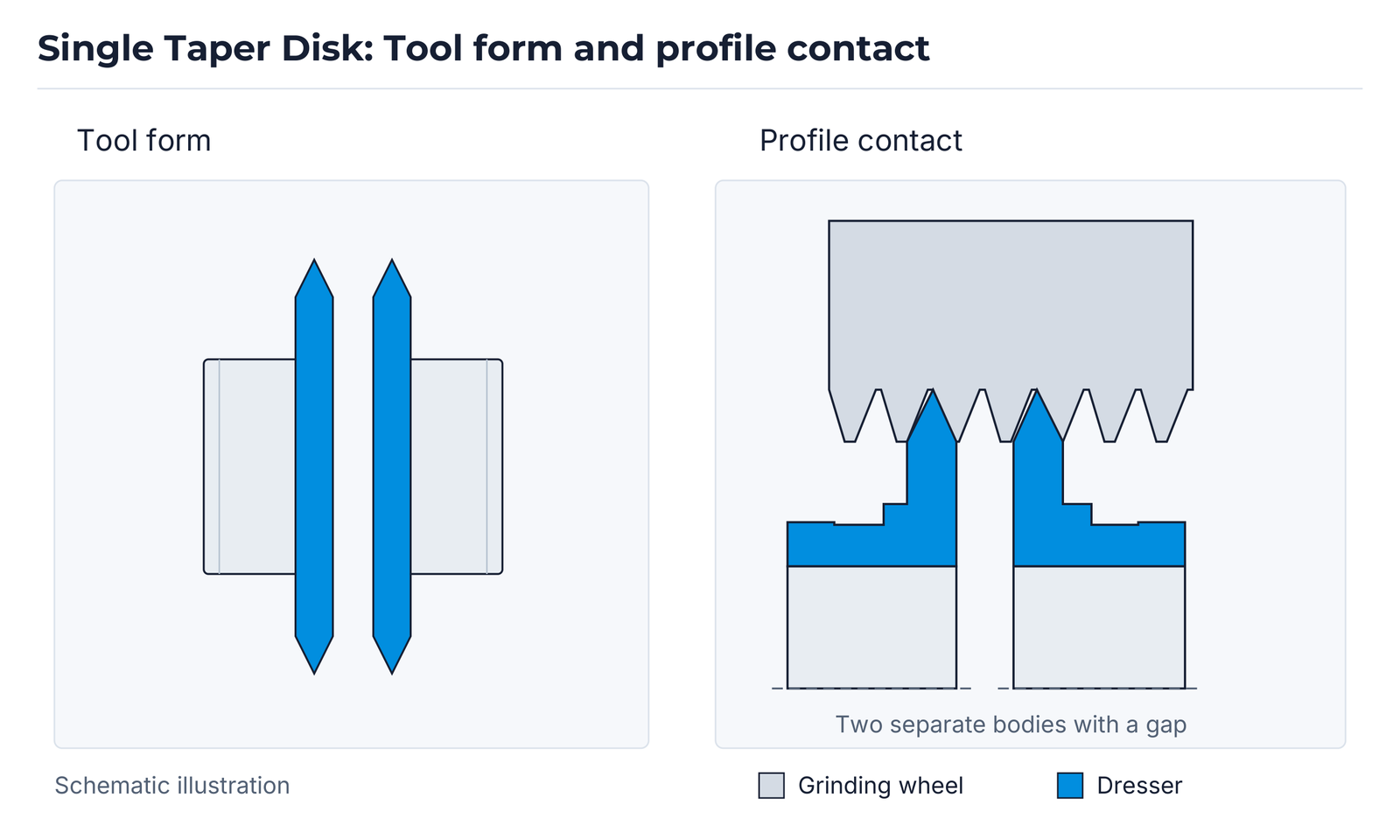

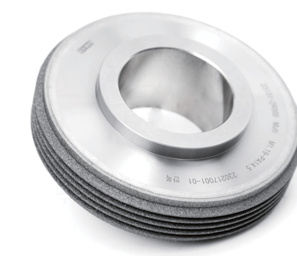
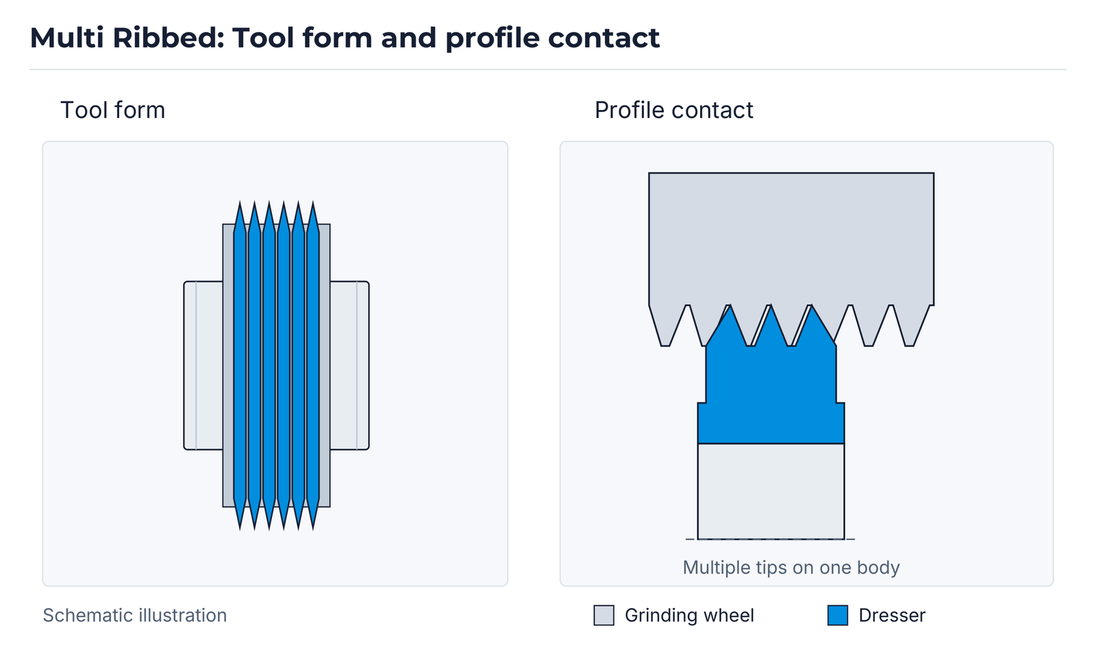
Sources and application engineering
This programme combines the main catalogue's fundamentals and applications with the separately identified tool variants in the two supplements. Trial results refer to the stated conditions. Workpiece material, machine, coolant, wheel form and bond determine the choice for your process.
- EHWA: Grinding, printed edition 02/2022, pages 1–108 (manufacturer catalogue).
- EHWA: Tooling, source file Tooling_2026_QR.pdf, pages 1–6 (manufacturer publication).
- EHWA: Grinding Wheels, source file Grindingwheels_AMB2026_2.pdf, pages 1–4 (manufacturer publication).
Contact EHWA Europe for tool selection and application engineering at info@ehwadia.de or +49 6173 997780.