Profiled tools for precise grinding processes
EHWA DIAMOND – since 1975
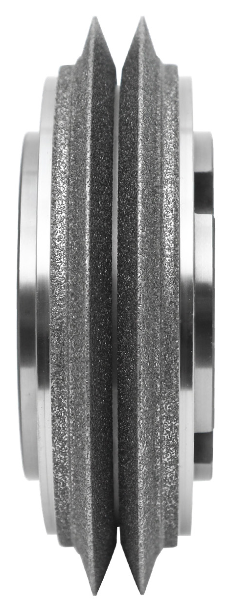
Precision starts with the dressing profile
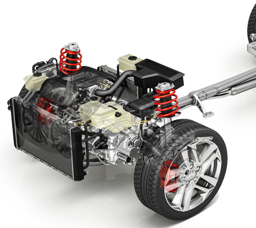
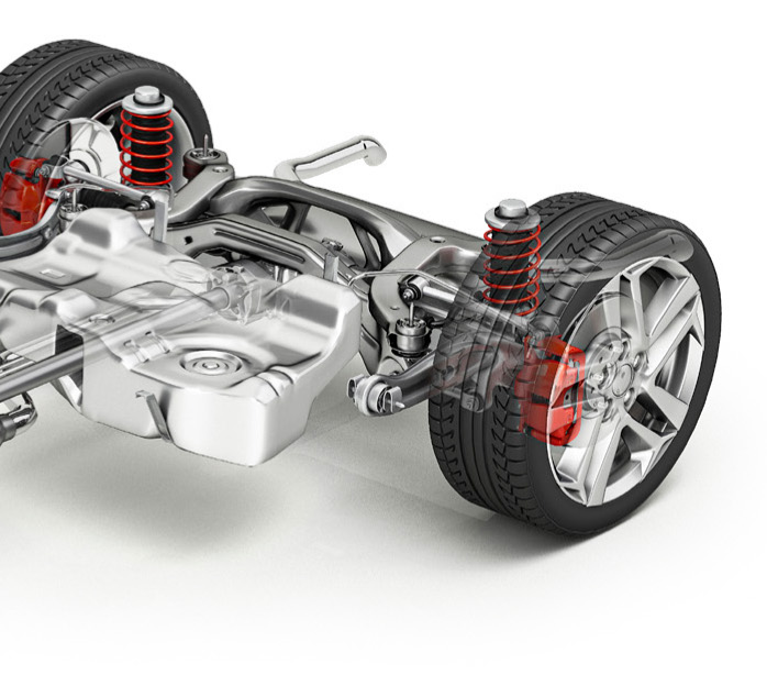
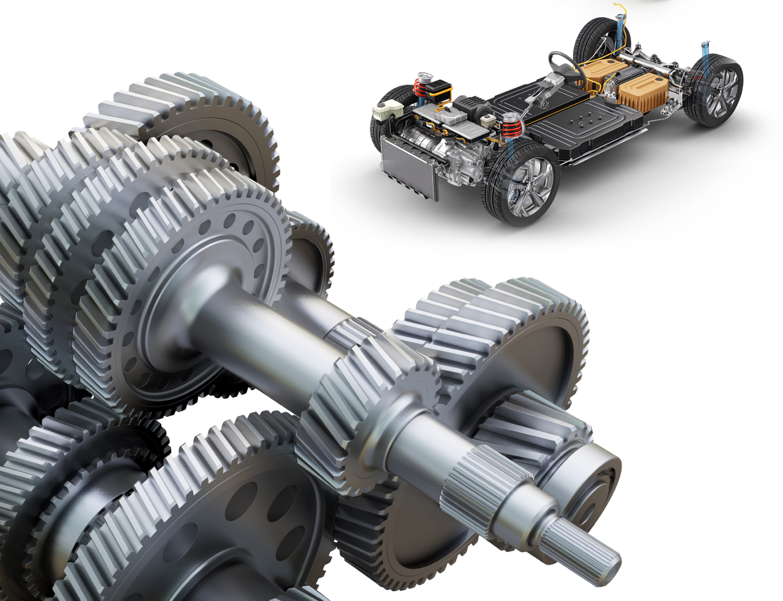
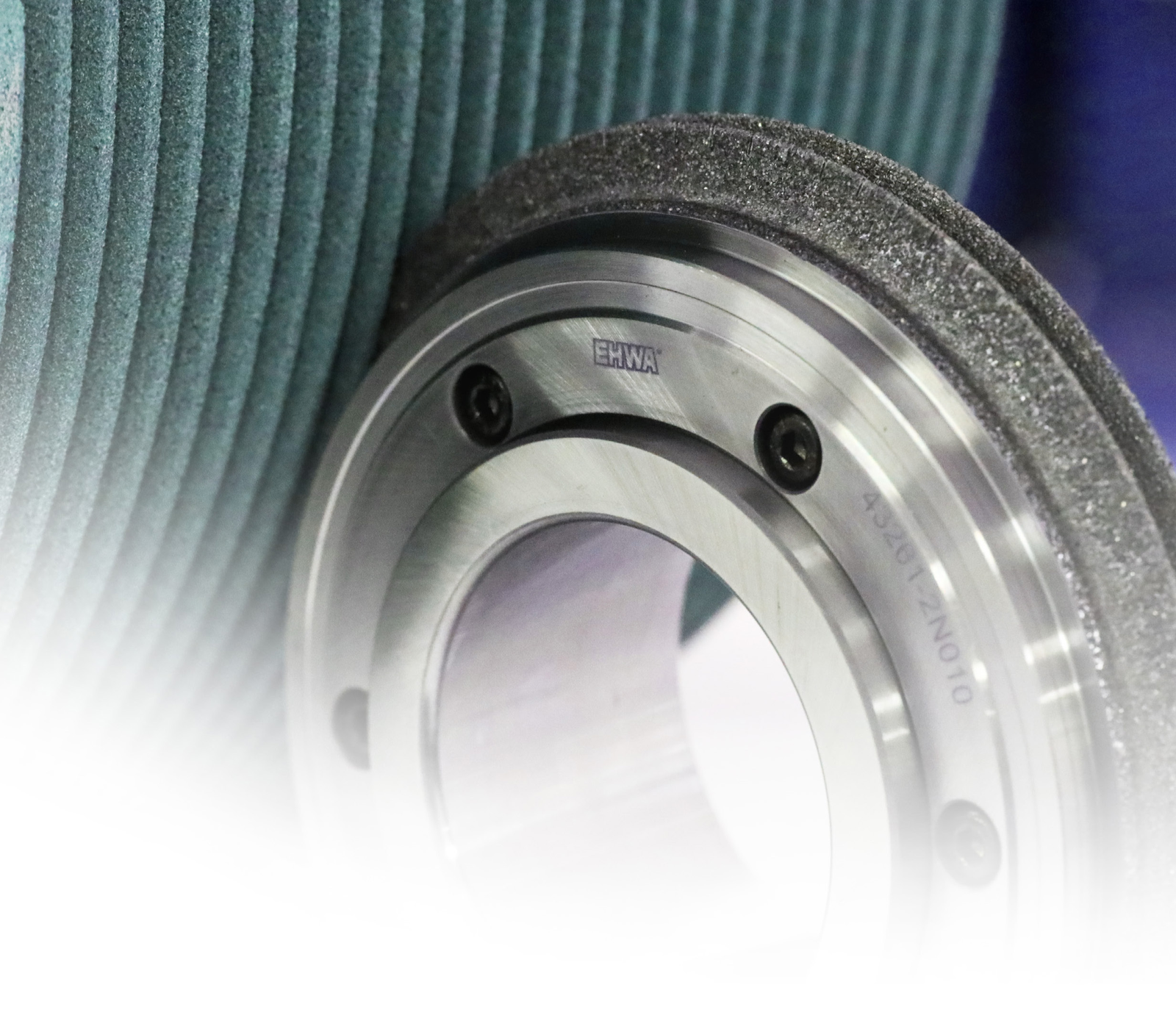
EHWA develops diamond dressing rolls for gear grinding and bearing manufacturing. Gear applications range from reduction gears for electric vehicles to transmission components in vehicles with internal-combustion engines. Increasing requirements for efficiency and quiet operation create a greater need for precise gears and accurately designed dressing tools.
Controlled raw-material selection, optimised manufacturing processes and precisely machined and polished dressing contours form the basis of tool quality. EHWA tailors the tools to the required profile and machining task. This allows the grinding-wheel contour, required precision and production sequence to be planned together.
The dresser profiles the grinding wheel or grinding worm. The grinding tool then machines the gear. The workpiece profile, grinding tool, dresser and machine therefore form a connected process chain. For bearing applications, the required workpiece contour is likewise matched to the grinding wheel being dressed.
Transmission gears for different drivetrains
Tool design takes account of the requirements of the drivetrain and gear geometry. Electric-vehicle reduction gears and transmissions for internal-combustion engines are the two explicitly illustrated application areas. Precision supports the objective of an efficient, quiet drivetrain; the achieved result depends on the overall transmission and manufacturing design.
| Application area | Dresser-design task |
|---|---|
| Electric-vehicle reduction gears | Precise grinding contour for the required gear geometry and quiet operation. |
| Transmission components for internal-combustion engines | Customer-specific profile for the transmission component. |
| Bearing manufacturing | Grinding-wheel profiles for ball, roller, hub and water-pump bearings. |
Comparing five tool designs
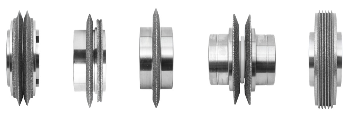
The five designs differ in the number and arrangement of their profile sections. The side views make the profiling visible, while the perspective photographs show the body and tool arrangement. The contact diagrams explain the relationship between the dresser and grinding-wheel profile. Profile dimensions, tolerances and mounting are specified for the particular application.
| EHWA designation | Profile principle |
|---|---|
| Single Cone | Single profile |
| Double | Two tips on a common body |
| Single & Root | Main profile with a lower root section |
| Single Taper Disk | Two separate profile sections |
| Multi Ribbed | Multiple adjacent profile ribs |
Single Cone
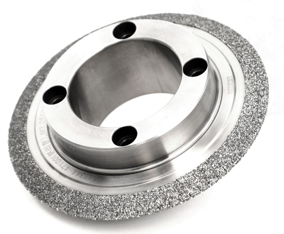
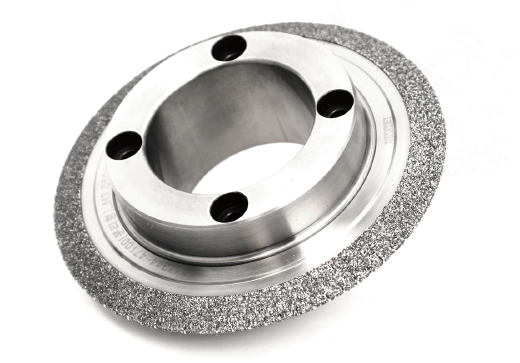
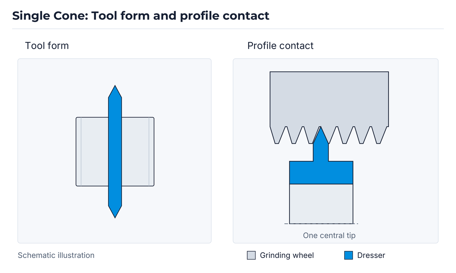
A single conical main profile. In the contact diagram, one central tip engages the grinding-wheel profile. The side view shows the two-sided form of the narrow single profile; the perspective photograph adds a view of the body and bore.
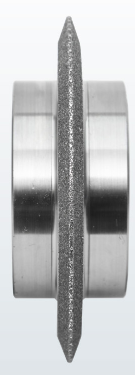
Double
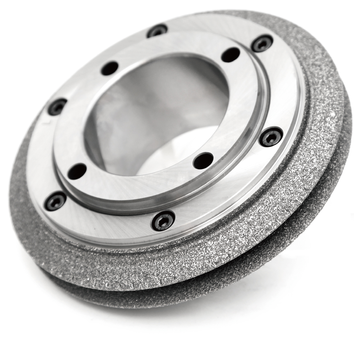
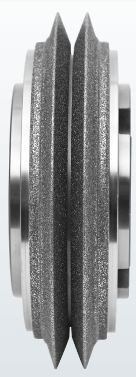
Two adjacent profile tips on a common body. Both tips are shown in the profile contact. The double design is illustrated in side view and as a complete dressing roll with its body and mounting holes.

Single & Root
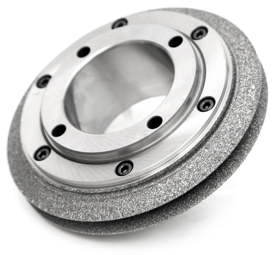
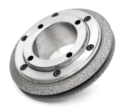
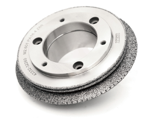
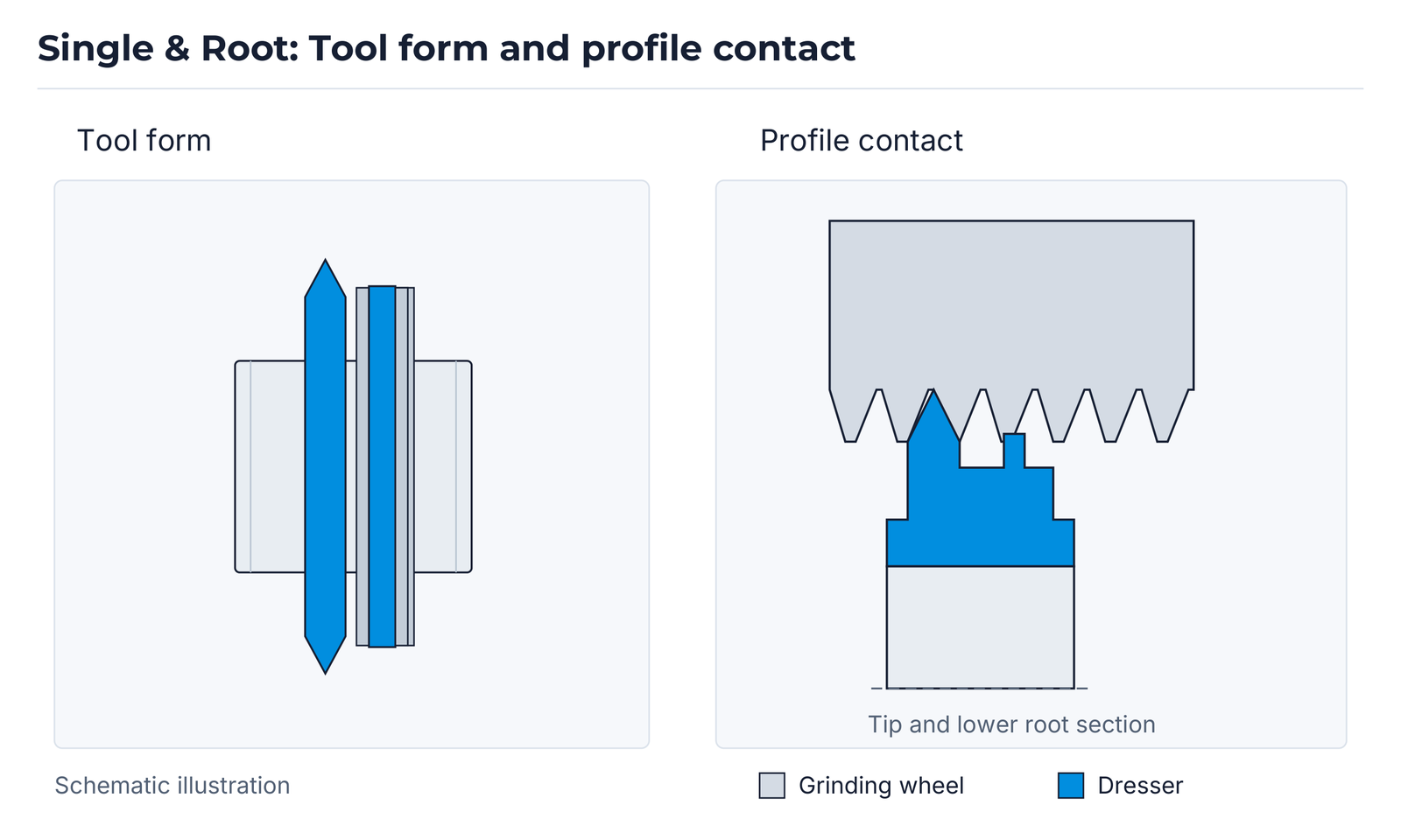
A taller main profile is combined with a lower root section. The contact diagram is asymmetric: the additional lower section is positioned next to the main tip. The main profile and root section are matched together to the required grinding contour.
Single Taper Disk
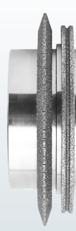
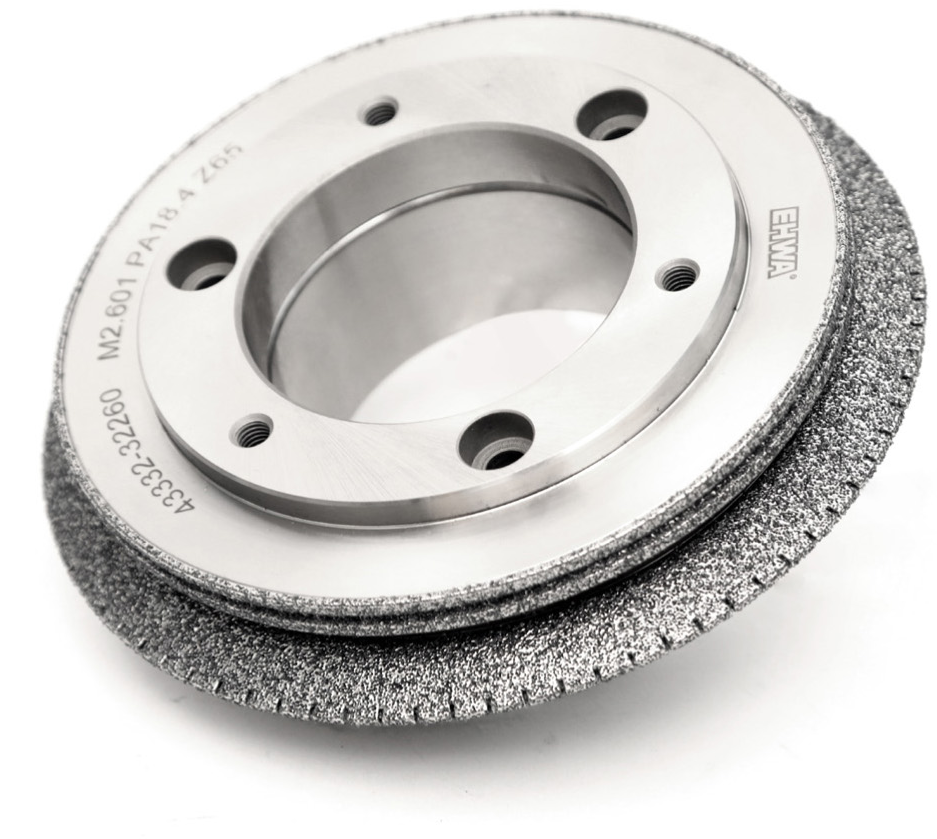
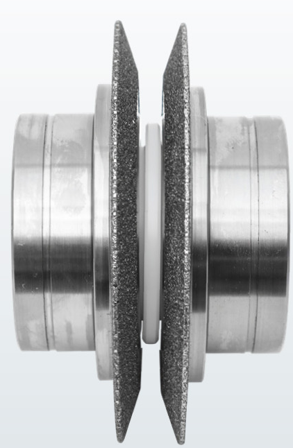
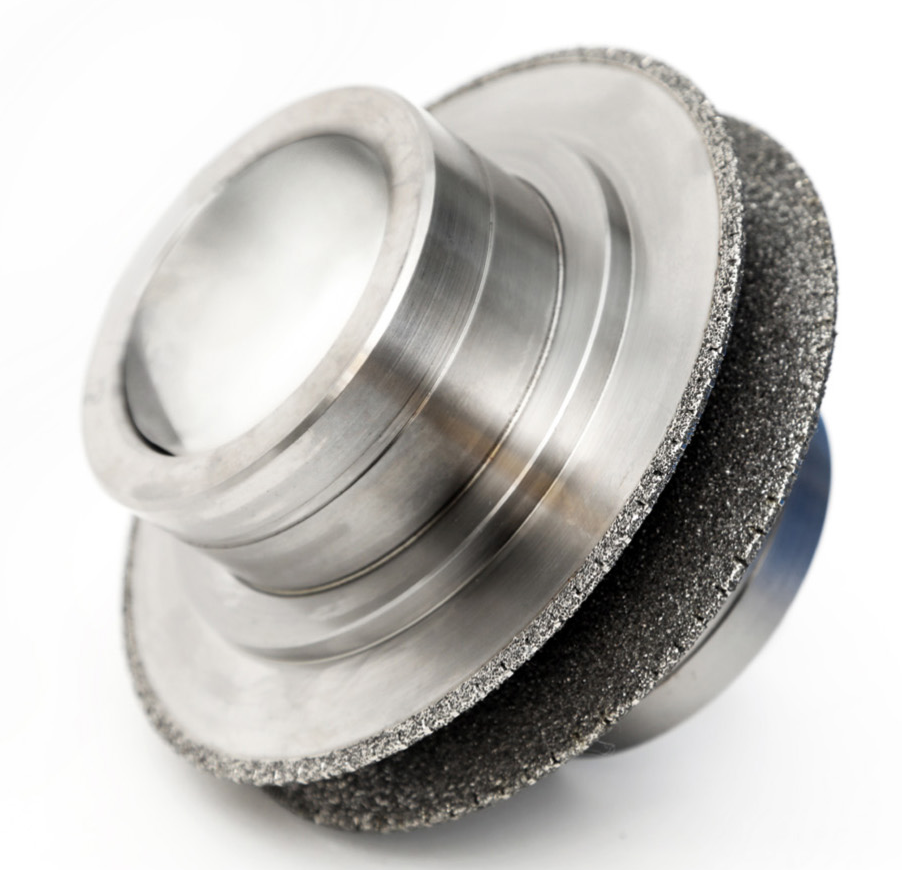
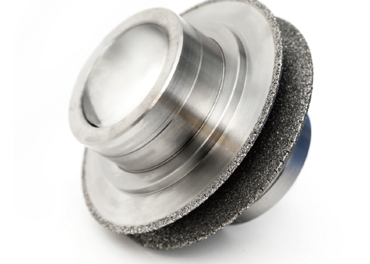
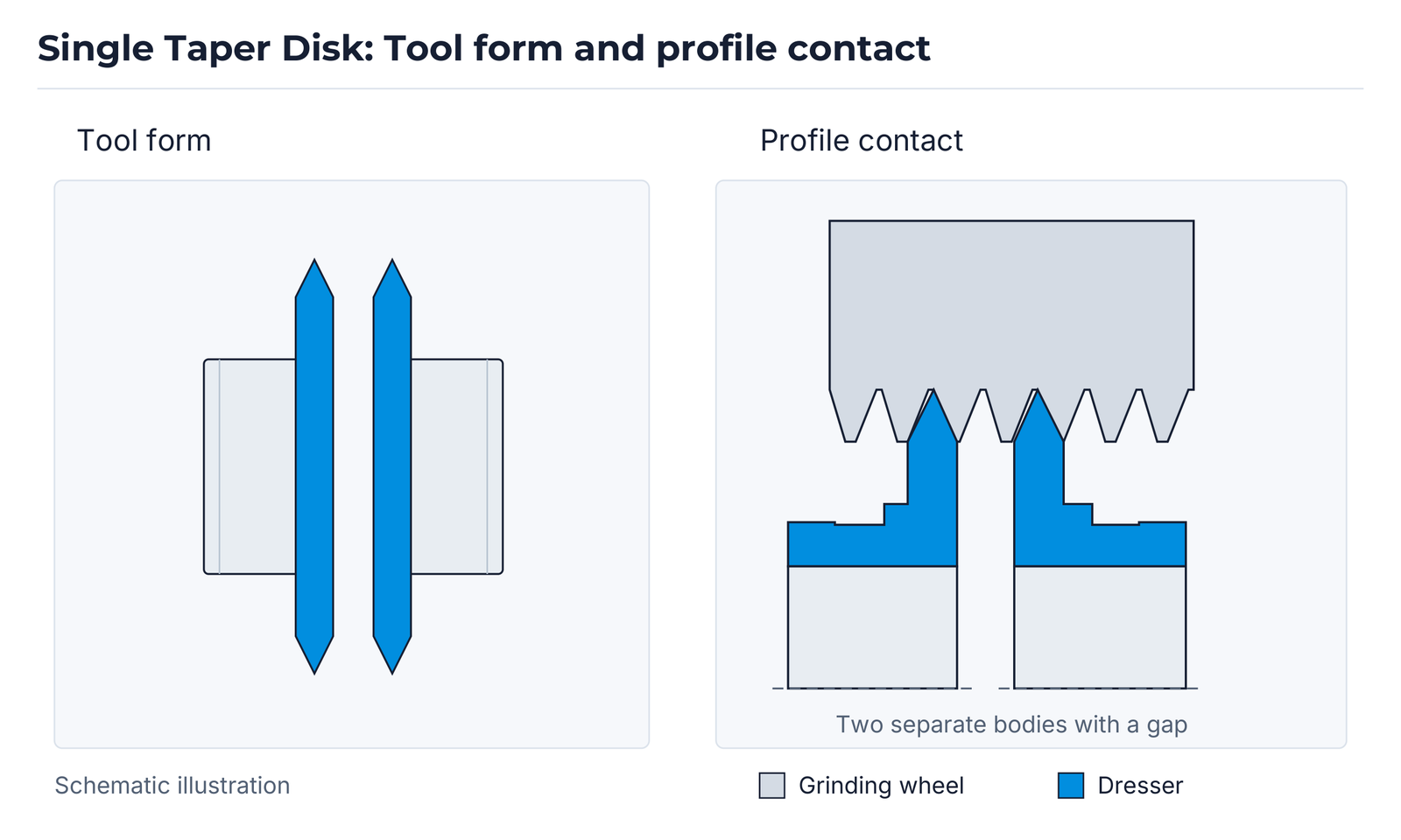
The illustrated design has two separate profile sections. In the contact diagram, the gap between the two sections extends down to the common reference line. The perspective view shows the tapered disc sections and their arrangement on the tool body.
Multi Ribbed
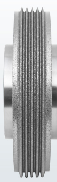
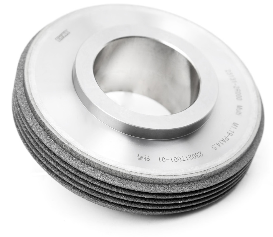
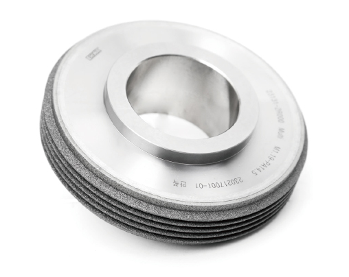
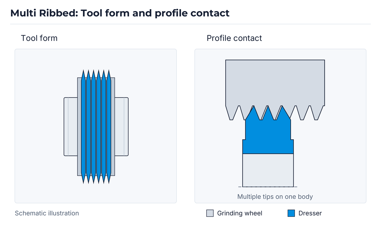
Multiple closely spaced profile ribs characterise this design. The contact diagram shows three tips on a common body; it illustrates the principle and does not specify the rib count for an ordered tool. The product views show the illustrated multiple-rib configuration.
Tool quality and repeatable design
Dressing-roll quality starts with strict control of the raw materials. Optimised production processes and precise profile finishing build on this foundation. EHWA identifies precisely machined and polished contours as a feature supporting the required gear profile in the subsequent grinding process.
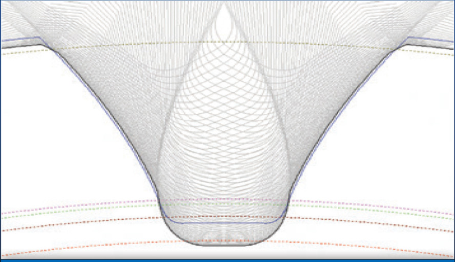
Design also includes simulation of the interacting profiles and material removal. This supports consistent tool quality and adaptation of the dresser contour to the customer’s task. Measurement and simulation complement each other: the measurement image shows profile evaluation, while simulation supports the geometric design.
Profile evaluation in the micrometre range
EHWA describes gear-profile precision in the micrometre range at the evaluated profile section. The measurement image presents left and right tooth flanks side by side and shows their profile traces. It is an example of profile evaluation; agreed limits and measurement conditions are defined with the component drawing.
The labels “left flank” and “right flank” identify the two tooth flanks, “PROFILE” the profile view and “Tooth” the tooth positions.

Profile and material-removal simulation
The illustrated simulation supports customer-specific optimisation of the dresser contour. EHWA identifies the hob-cutter/worm-wheel pairing and incorporates the grinding and removal amounts of the interacting tool profiles into the design. The “Hobbing and Grinding Simulation” image contains overlaid profile traces and illustrates the geometric matching process.
Gear, dresser-body and hob-cutter drawings are combined with grinding-machine information for the design. The particular tool pairing and its removal amounts are defined for the project.

Eight items for gear-dresser design
Please compile the drawings and information listed in the checklist. For the selection fields, indicate the applicable option. Complete information helps match the gear geometry, tool profile and machine.
| No. | Required information | Document / selection |
|---|---|---|
| 1 | Gear drawing | Attach drawing. |
| 2 | Gear modification data | Attach modification data. |
| 3 | Gear root grinding | Yes / No |
| 4 | Pressure angle shifted | Yes / No |
| 5 | Dresser body drawing | Attach drawing. |
| 6 | Gear loading direction: grinding versus measuring | Same / Opposite |
| 7 | Gear grinding machine model | Specify machine model. |
| 8 | Hob cutter drawing | Attach drawing. |
Rotary diamond dressers for bearings
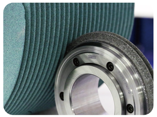
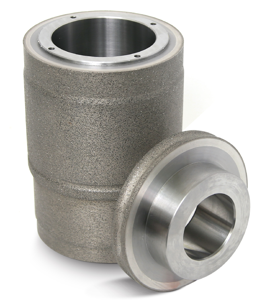
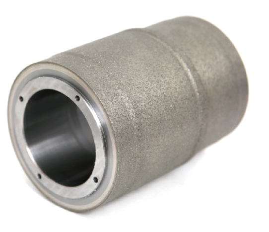
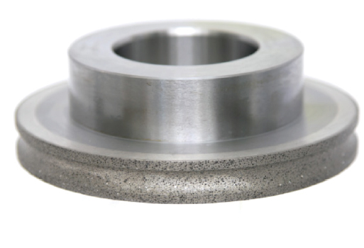
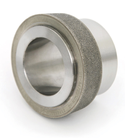
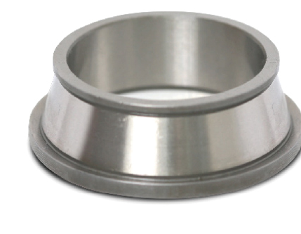
Applications cover ball, roller, hub and water-pump bearings. Profiled dressing rolls support precise machining even in complex grinding tasks. EHWA identifies reduced dressing load with effective dressing, longer tool usage and shorter machining cycles as advantages. The range also includes designs for dressing vitrified-bonded CBN grinding wheels.
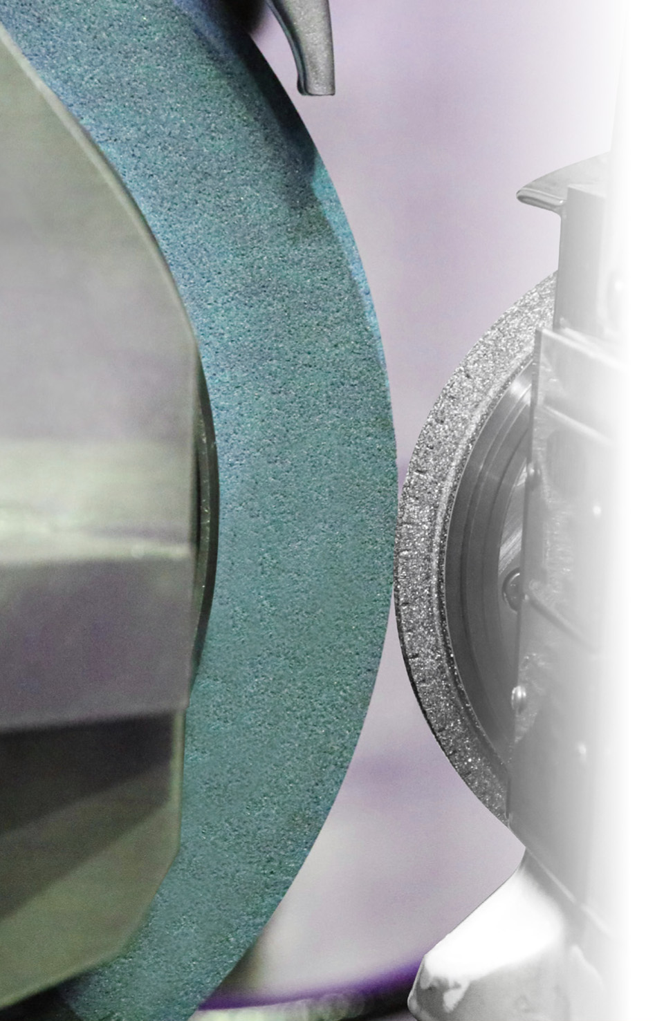
Matching the grinding-wheel bond, contour and dressing process connects these features to the bearing application. The two tool bodies in the photograph show different dresser forms for such tasks.
Three dresser-to-bearing examples
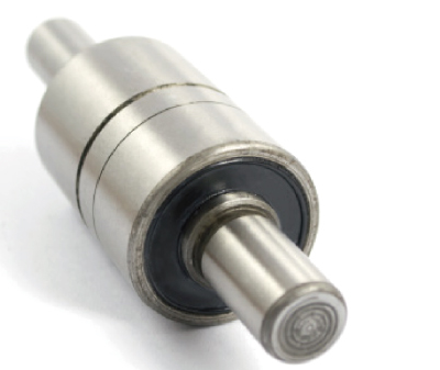
The three application examples each pair a dressing roll with a bearing or bearing ring. Roller bearings are also included in the general application range. These examples show how the dresser form follows the required grinding contour.
| Application | Illustrated pairing |
|---|---|
| Water-pump bearing | Rotary dressing roll and shaft/bearing component. |
| Ball bearing | Profiled dressing roll and several ball bearings. |
| Taper hub bearing | Dressing roll and tapered bearing ring. |

Developing your profile together
For gear applications, the complete checklist is the basis for design. Add the grinding-wheel specification and existing dresser mounting. For bearings, provide the bearing type, component drawing, surface to be machined and grinding-wheel bond. Existing profile measurements, dressing cycles and quality findings help match the required precision and production sequence.
EHWA Europe: info@ehwadia.de · +49 6173 997780
Technical basis
EHWA: Gear Grinding Dresser, printed edition 02/2024, pages 1–6. EHWA: Gear Grinding Dresser / Rotary Dressers for Bearings, pages 1–2. This edition combines the gear and bearing applications of both documents. Editorial issue: 13 October 2026.