Diamond and CBN tools for profiles, surfaces and cutting edges
From the workpiece to the right grinding wheel
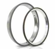
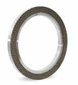
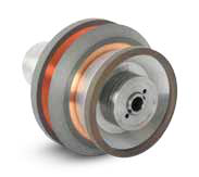
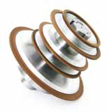
EHWA offers grinding wheels for producing and machining a range of cutting tools. These include periphery and top-and-bottom grinding wheels for inserts, hybrid and precision wheel packs for rotary tools, and tool-grinding wheels for tipped circular saws. The range also covers taps, burrs, HSS saw blades, hobs and broaches.
The cutting tools are distinguished by their workpiece material: high-speed steel, carbon steel, ceramic, carbide and PCD/PCBN materials. Tungsten-containing cemented-carbide tools are a major application. Workpiece material, abrasive and bond are selected separately; the HSS profile-grinding example explicitly specifies CBN.
| Workpiece / operation | EHWA tool family |
|---|---|
| Insert periphery | Periphery wheels |
| Insert top and bottom surfaces | Top & Bottom wheels |
| Rotary tools | Hybrid wheel packs |
| Micro rotary tools | Precision wheel packs |
| Tipped circular saws | Tool-grinding wheels |

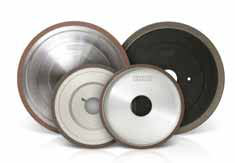
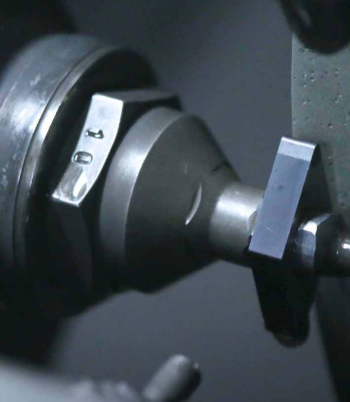
Inserts: periphery, top and bottom
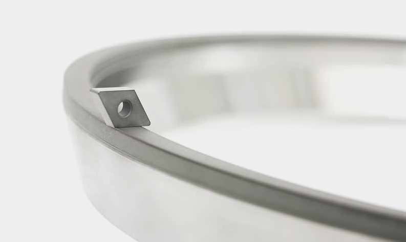
The range includes grinding wheels for carbide, ceramic, cermet and PCD/PCBN inserts. Tool design, cycle time and dressing interval are considered together. The aims are uniform insert geometry, a fine surface finish and small cutting-edge chips.
| Operation | Stated benefits | Machine examples |
|---|---|---|
| Periphery grinding | Shorter cycle times with suitable high feed rates; small chips; longer dressing intervals | Agathon, Wendt, Waida, Ewamatic, Ewag |
| Top-and-bottom grinding | Shorter cycle times; longer dressing intervals; improved dimensional stability | Stahli, Peter Wolters, Wendt WBM, Agathon T&B, Fujisanki |

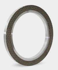
Bond selection by application
The selection matrix contains the bond designations for periphery and top-and-bottom grinding. It distinguishes standard resin, high-performance resin and hybrid bonds, with an additional qualitative bond-strength direction for PCD/PCBN.
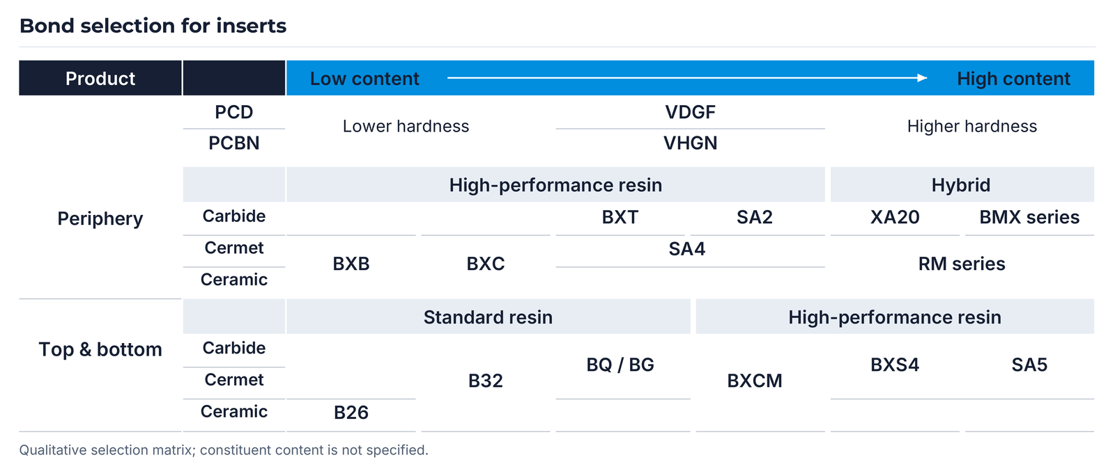
The matrix lists VDGF for PCD and VHGN for PCBN. The periphery-grinding section contains BXB, BXC, BXT, SA2, SA4, XA20, BMX series and RM series. The top-and-bottom section contains B26, B32, BQ / BG, BXCM, BXS4 and SA5. The positions and shared areas of these designations remain visible in the matrix.
The upper arrow is labelled “Low content / High content”. The constituent concerned is not identified; the appropriate bond is selected using the complete workpiece-material specification.
Three insert-grinding application examples
For periphery grinding, EHWA describes high-temperature polyimide bonds together with hybrid and soft metal bonds. The design combines shorter cycle times, small chips, dimensional stability and productivity. The following examples concern different workpieces and tool designs.
1. Carbide inserts on Wendt
| Trial specification | Design |
|---|---|
| Machine | Wendt 715 WAC Quattro |
| Workpiece | Carbide insert |
| Wheel speed | 20 m/s |
| Wheel specification | RD-11A2, 400D-39T-10W-6X-355.06H |
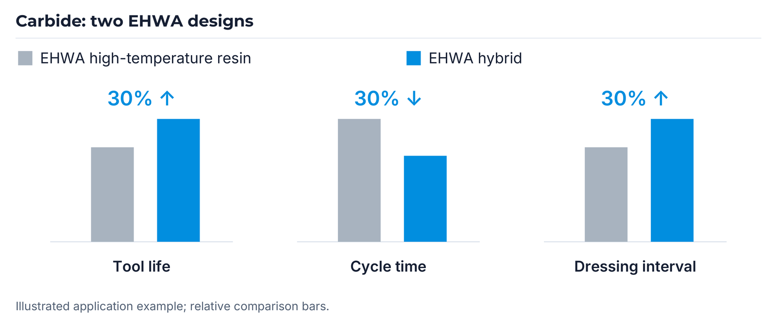
| Compared designs stated by EHWA | D46 high-temperature resin bond; D40 hybrid bond |
In the illustrated comparison, EHWA states 30% longer tool life, 30% shorter cycle time and a 30% longer dressing interval for the hybrid design compared with the high-temperature design shown.
2. PCBN inserts on Agathon
| Trial specification | Design |
|---|---|
| Machine | Agathon |
| Workpiece | PCBN insert |
| Wheel speed | 18 m/s |
| Wheel specification | VD-11A2, 400D-39T-15W-6X-355.06H |
| Designation | D6M120VHGN |
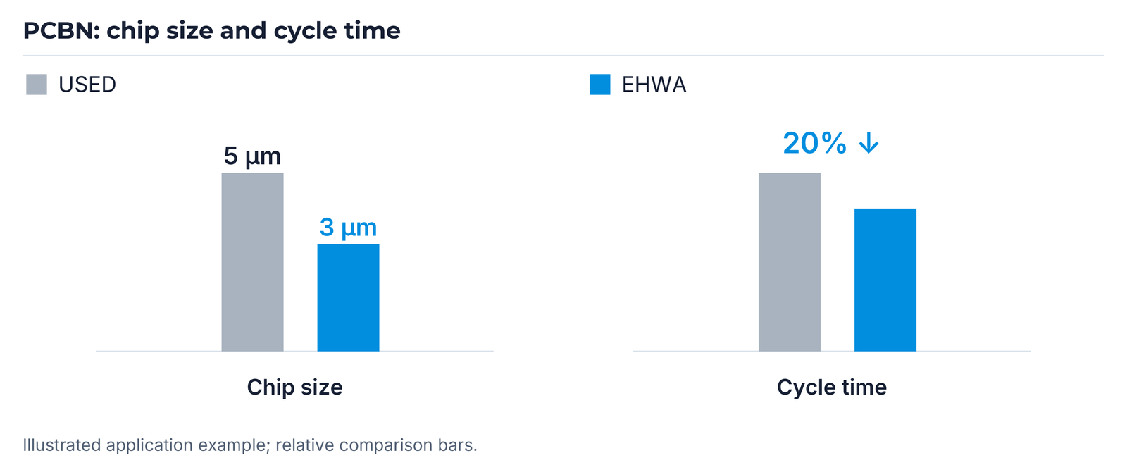
The illustrated chip size is 5 µm for the comparison design labelled USED and 3 µm for EHWA. The example also states a 20% shorter cycle time.
3. Top-and-bottom grinding of different carbide inserts
| Trial specification | Design |
|---|---|
| Machine | Wendt WBM221-Duo Lift |
| Wheel | RD-2A2T, 501D-5X-40W, D126BXS4 |
| Workpiece | Different carbide inserts |
| Coolant | Oil |
In the illustrated comparison with a competitor's tool, EHWA states 20% longer tool life and a 30% longer dressing interval.
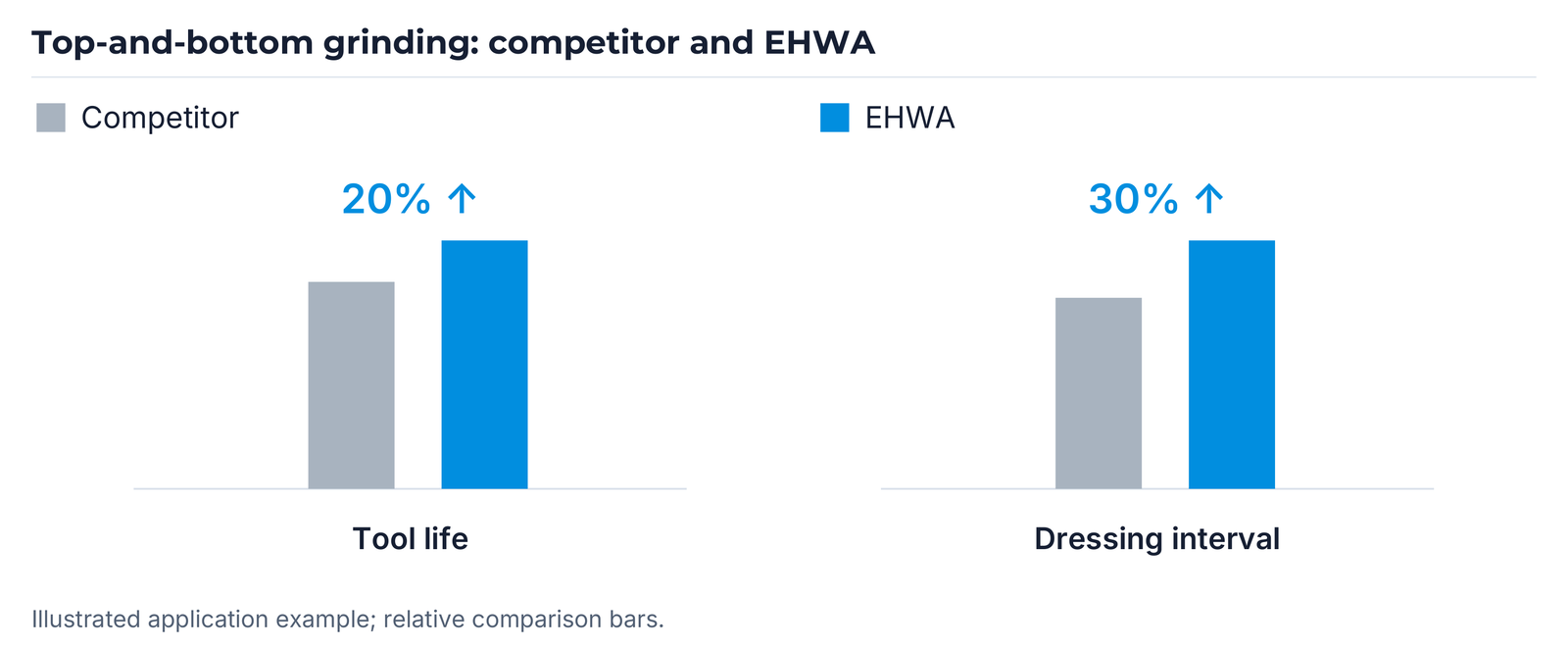
Each result refers to the designs and trials shown.
Rotary tools: polyimide, hybrid and porous structures
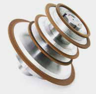
For rotary tools, EHWA describes polyimide bonds as more thermally stable than phenolic or epoxy bonds within the tool-grinding range considered. This stability supports grinding performance and tool life.
Hybrid bonds combine polyimide and metal bonds. The design combines the grinding performance and elasticity of polyimide with the wear resistance and thermal stability of the metal component.
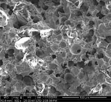
A porous hybrid structure supports diamond protrusion and improves coolant access. Lower grinding load can enable suitable higher feed rates and reduce cycle time.
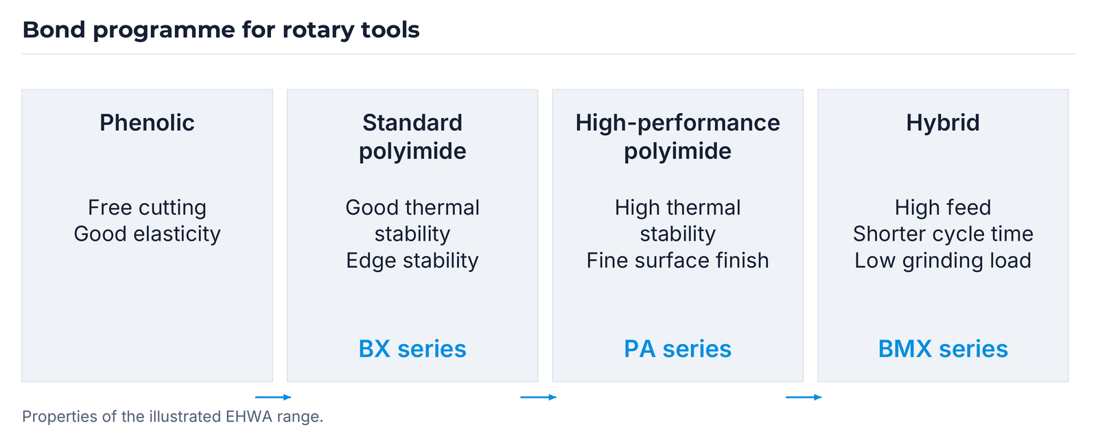
| Bond programme | Stated properties | Series designation |
|---|---|---|
| Phenolic bond | Free-cutting behaviour; good elasticity | — |
| Standard polyimide bond | Good thermal stability and edge stability | BX series |
| High-performance polyimide bond | High thermal stability; fine surface quality | PA series |
| Hybrid bond | Shorter cycle time through high feed; low grinding load | BMX series |


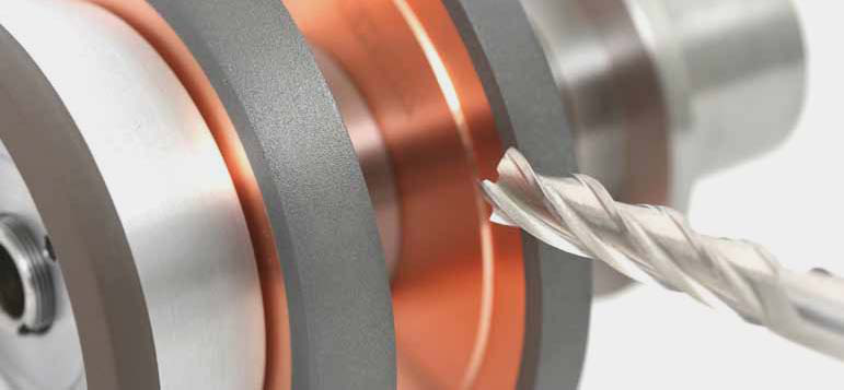
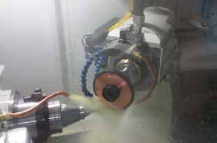
Drills and end mills: spindle-load comparison
| Trial specification | Value |
|---|---|
| Machine | ANCA FX7 (19 kW) |
| Workpiece description | Carbide Φ12–50mm (LOF), 2 flutes (K10) |
| Wheel speed | 18 m/s |
| Feed rate | 120 mm/min |
| Depth of cut | 2.4 mm |
The notation Φ12–50mm (LOF) comes from the trial sheet. Diameter and length specifications are agreed separately for the particular tool design.

In this example, the curves show a lower spindle load for the new porous hybrid bond at the same part count. The axes indicate spindle load as a percentage and the number of ground parts.
Precision and micro rotary tools
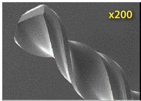
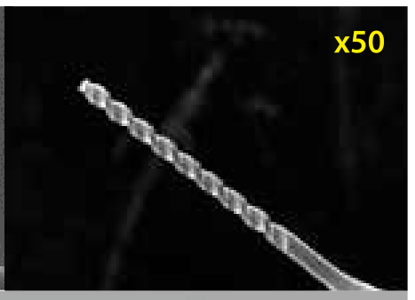
For precision tools, EHWA states high productivity with low tooling costs, improved surface and cutting-edge quality, and accurate edge stability. The micrographs show two tool examples at the stated magnifications.
Taps and burrs
| Application | Tool type / specification | Function |
|---|---|---|
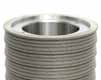
| Taps | VB-1A1 | Grinding |
| Taps | R/D-RR | Dressing |
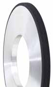
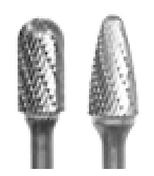
| Burrs | MD-1V1; 110D–160D / 30V–60V; ME4 series | Grinding tool and bond series |
The D/V notation in the burr specification is retained as a manufacturer designation; the tool drawing defines the particular design.

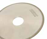

Tipped circular saws: flank, top and face
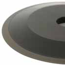
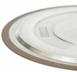
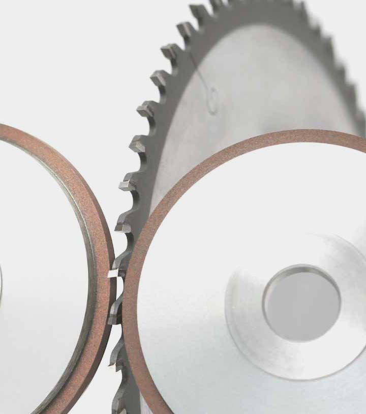
For tipped circular saws, EHWA states long tool life, shorter cycle time, fine surface finish and high dimensional stability. Three grinding surfaces are distinguished: flank, top and face.
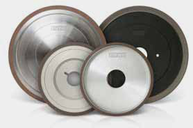
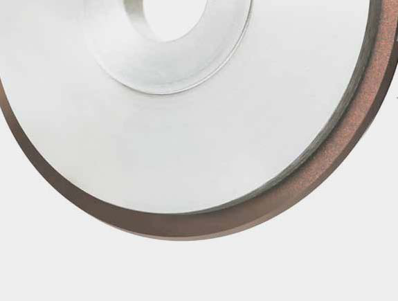
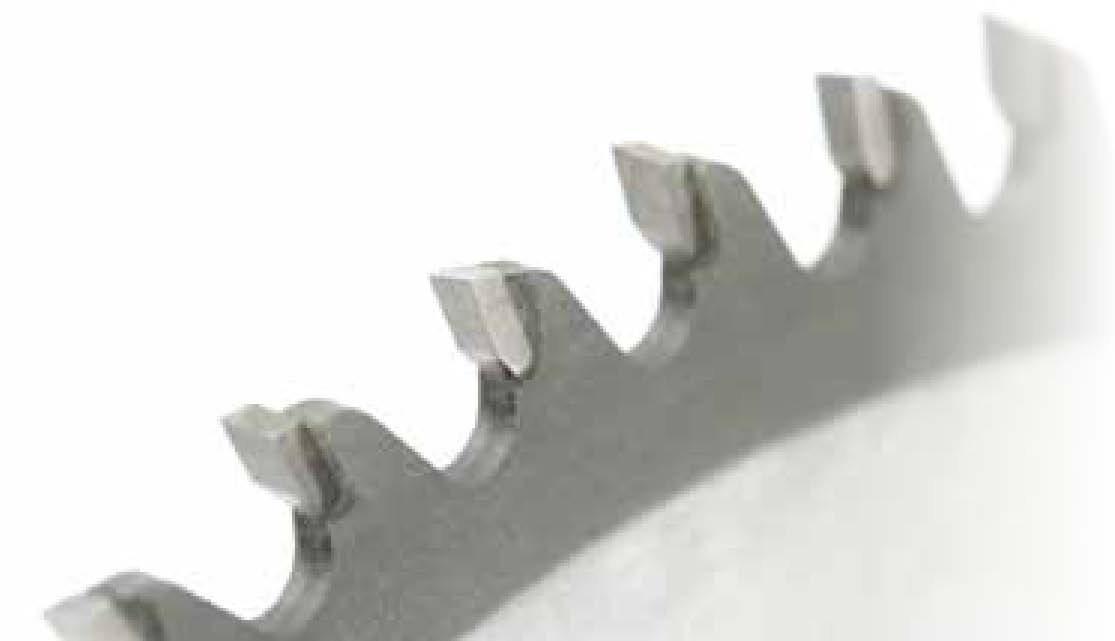
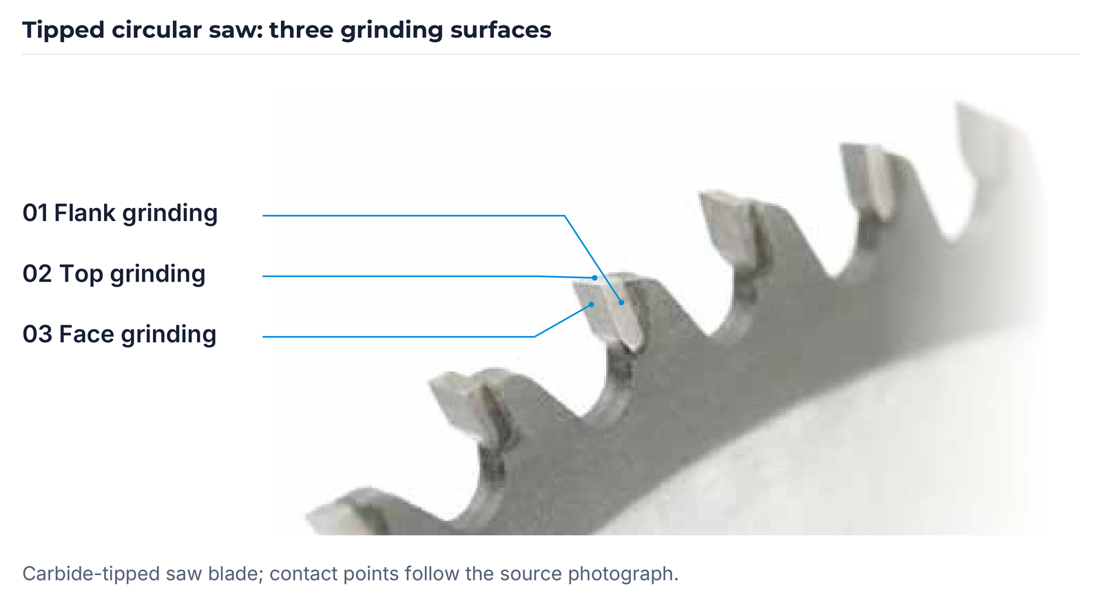
| Workpiece | Grinding surface |
|---|---|
| Carbide-tipped circular saw | Flank |
| Carbide-tipped circular saw | Top |
| Carbide-tipped circular saw | Face |
| HSS saw blade | Profile |
HSS profile grinding, hobs and broaches
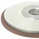
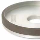
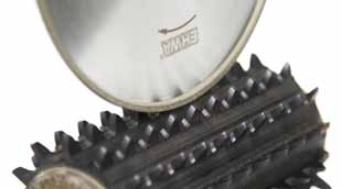
For profile grinding of HSS saw blades, EHWA specifies RB-14F1/S, CBN107 and a hardened resin bond. The complete selection contains two D groups with the same five combinations:
| Type | D | x1 | x2 | U | Bond type |
|---|---|---|---|---|---|
| RB-14F1/S | 150 | 6 | 8 | 1; 1.3; 1.6; 2; 2.5 | Hardened resin bond |
| RB-14F1/S | 150 | 6 | 10 | 3 | Hardened resin bond |
| RB-14F1/S | 150 | 8 | 12.5 | 3.5 | Hardened resin bond |
| RB-14F1/S | 150 | 8 | 12.5 | 4 | Hardened resin bond |
| RB-14F1/S | 150 | 10 | 15 | 5; 6 | Hardened resin bond |
| RB-14F1/S | 200 | 6 | 8 | 1; 1.3; 1.6; 2; 2.5 | Hardened resin bond |
| RB-14F1/S | 200 | 6 | 10 | 3 | Hardened resin bond |
| RB-14F1/S | 200 | 8 | 12.5 | 3.5 | Hardened resin bond |
| RB-14F1/S | 200 | 8 | 12.5 | 4 | Hardened resin bond |
| RB-14F1/S | 200 | 10 | 15 | 5; 6 | Hardened resin bond |
D, x1, x2 and U are the selection's dimensional designations. The binding dimensional definitions and units are agreed using the tool drawing.
Discuss your cutting-tool production
Specify the cutting tool, workpiece material and surface to be ground. Add the drawing, machine, mounting arrangement, current grinding wheel, coolant and required cutting-edge quality. For an existing process, cycle time, dressing interval, chipping and wear pattern are useful.
The tool design combines grinding performance, dimensional stability and useful tool life. The information available is sufficient to start; further details can be added during the technical discussion.
EHWA Europe: info@ehwadia.de · +49 6173 997780
Editorial date: 13 October 2026. Technical basis: EHWA, Cutting Tools.