EHWA DIAMOND – since 1975
Tools for bearing manufacture and related precision processes
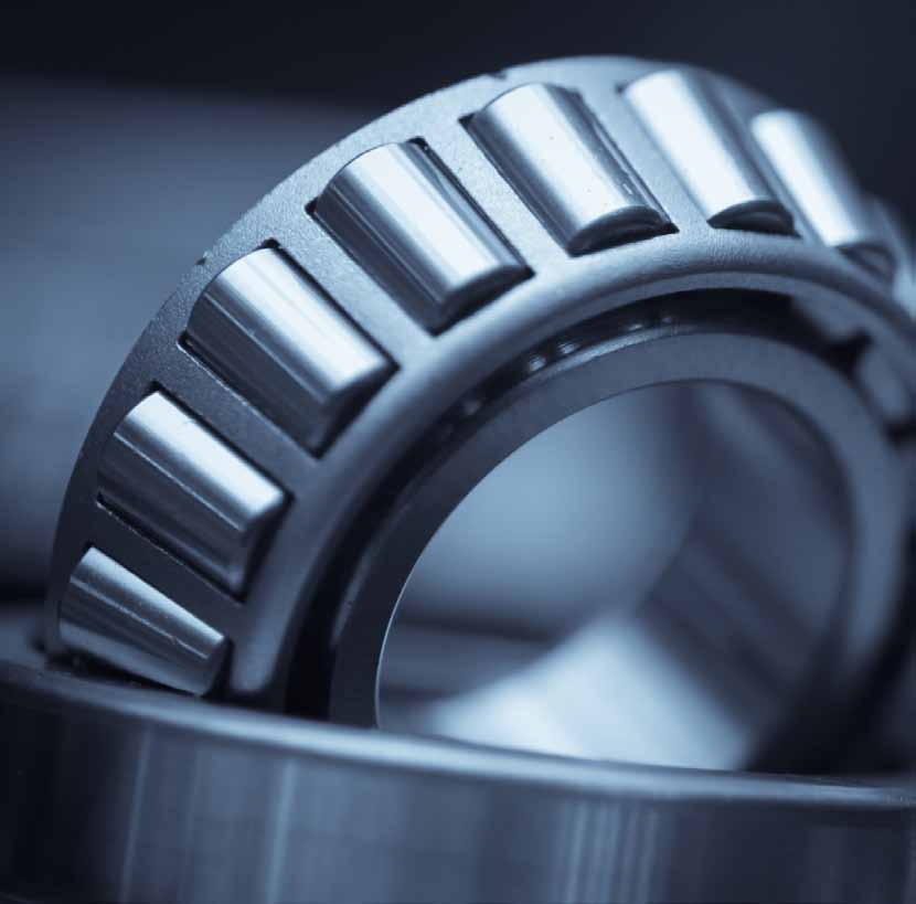
Bearing components place demanding requirements on raceway geometry, cylindricity, end faces and surface finish. EHWA combines vitrified CBN grinding tools with superfinishing stones and diamond dressing tools. The range covers internal and raceway grinding, face and double-disc grinding, and profiles for linear guides and ball screws.
The underlying EHWA documents also cover CV joints, injector bores and the manufacture of rotary tungsten carbide tools. These related applications have their own chapters, including their tools, test data and micrographs. The bearing document describes EHWA's collaboration with leading bearing and aircraft engine manufacturers; the data presented here support technical selection for the particular manufacturing task.
| Manufacturing task | Tool family | Focus |
|---|---|---|
| Bore, inner and outer raceways, lip and ring end face | Vitrified CBN tools | Stock removal, geometric accuracy and low thermal load |
| Superfinishing bearing raceways | CBN honing stones | Fine surface finish and consistent machining |
| Dressing bearing grinding wheels | Diamond rotary dressers and metal cup dressers | Contour, dressing performance and dimensional stability |
| Ring and roller end faces | Face, double-disc and horseshoe wheels | Productivity and surface finish |
| Linear guides and ball screws | Profile rotary dressers | Defined raceway profiles |
| CV joints and injector components | Dedicated CBN mounted grinding tools | Component-specific geometry and process performance |
| Rotary and micro tools | Porous hybrid, polyimide and MNC wheels | Flutes, cutting edges and profile stability |
The technical ranges and comparisons relate to the EHWA applications shown. Workpiece, machine, grinding wheel, dressing and coolant are coordinated for the particular process. Editorial version: 13 October 2026.
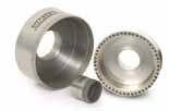
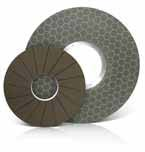
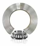
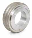
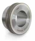
Vitrified CBN tools for bearing rings
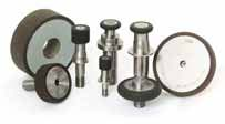
Vitrified CBN wheels and mounted grinding tools are designed for high stock removal and precision grinding of bearing surfaces. The source documents describe higher removal rates and shorter cycle times with reduced grinding forces. Lower mechanical and thermal loading supports consistent machining, good surface finish and cylindricity, and less dimensional deviation.
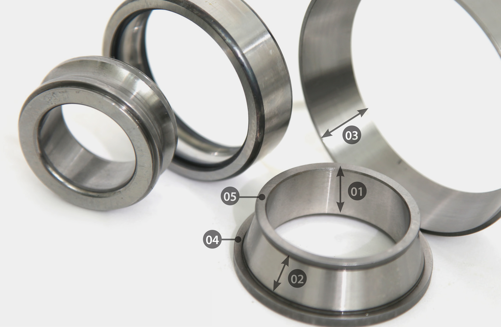
The five positions on the bearing ring distinguish the grinding surfaces:
| Position | Source abbreviation | Grinding surface |
|---|---|---|
| 01 | ID | Inner race internal diameter |
| 02 | IR | Inner raceway |
| 03 | OR | Outer raceway |
| 04 | Lip | Lip or adjoining shoulder |
| 05 | Ring face | Ring end face |
Process ranges in both bearing documents
| Parameter | EHWA specification |
|---|---|
| Wheel speed | 30–80 m/s |
| Stock removal, on diameter | 0.1–0.35 mm D |
| Dressing amount | 5–30 µm |
| Dressing ratio | 0.3–0.6 |
| Dressing tool | Diamond rotary dresser |
| Coolant | Oil or emulsion |
These specifications agree in the two bearing editions used here. Dressing ratio conventionally describes dresser peripheral speed divided by grinding wheel peripheral speed. Rotation direction and machine convention form part of process selection; the source does not separate the stated range by direction.
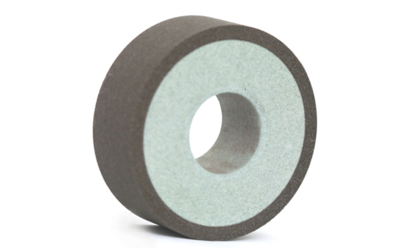
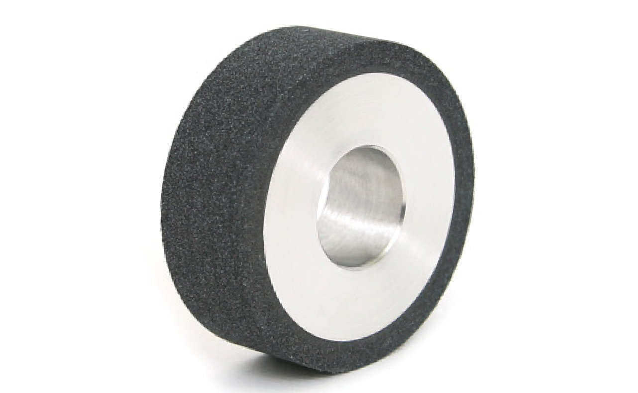
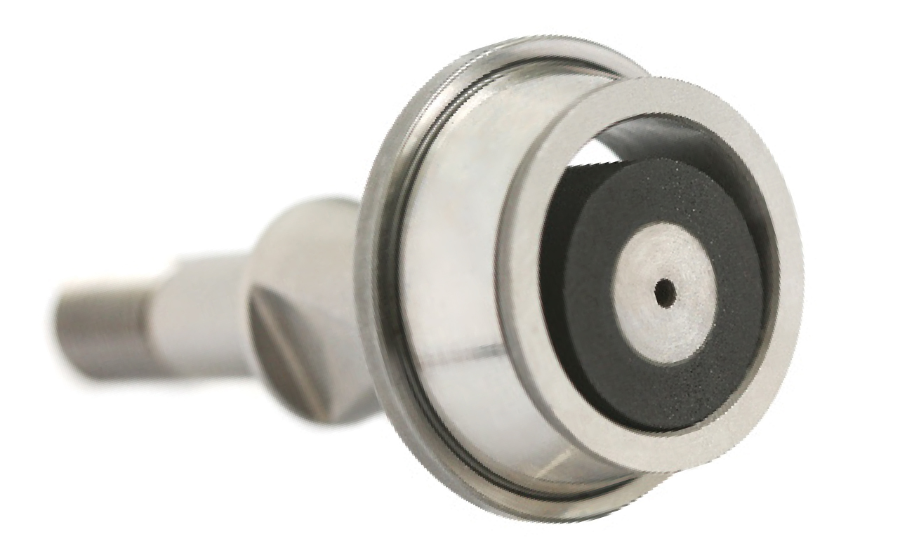
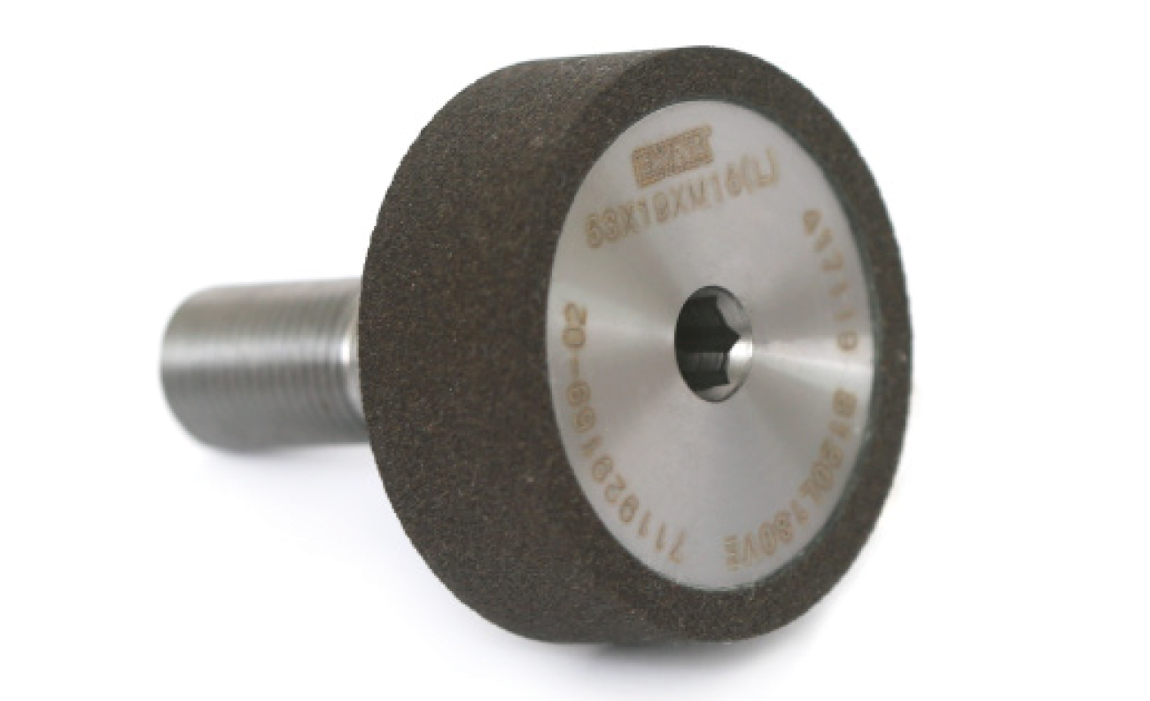
Four core and mounting designs
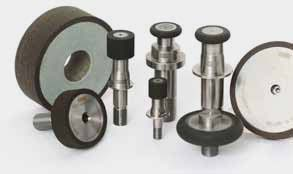
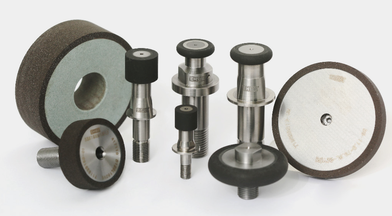
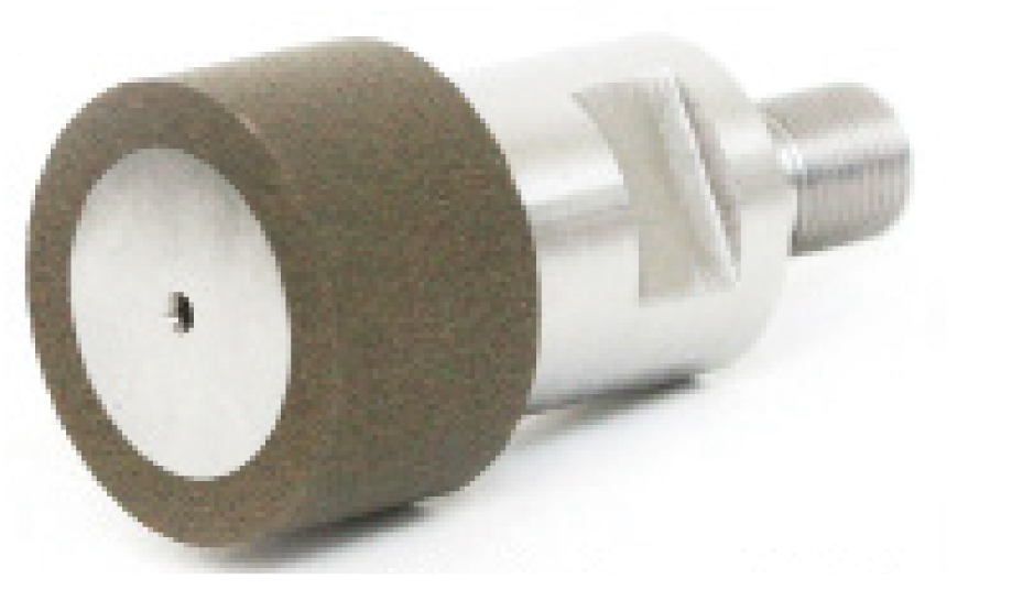
Ceramic core, steel core, steel quill and steel head are four distinct tool constructions. Selection combines the required grinding geometry with the mounting and available space. The illustrations retain all designs and the separate detail views from both documents.

CBN stones for superfinishing
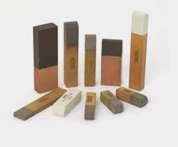
Superfinishing stones improve the raceway surface after grinding. The EHWA document describes shorter honing cycles, higher removal rates and improved surface finish. It states a tool life advantage of five to ten times that of conventional stones; the following application provides a specific comparison.
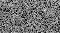
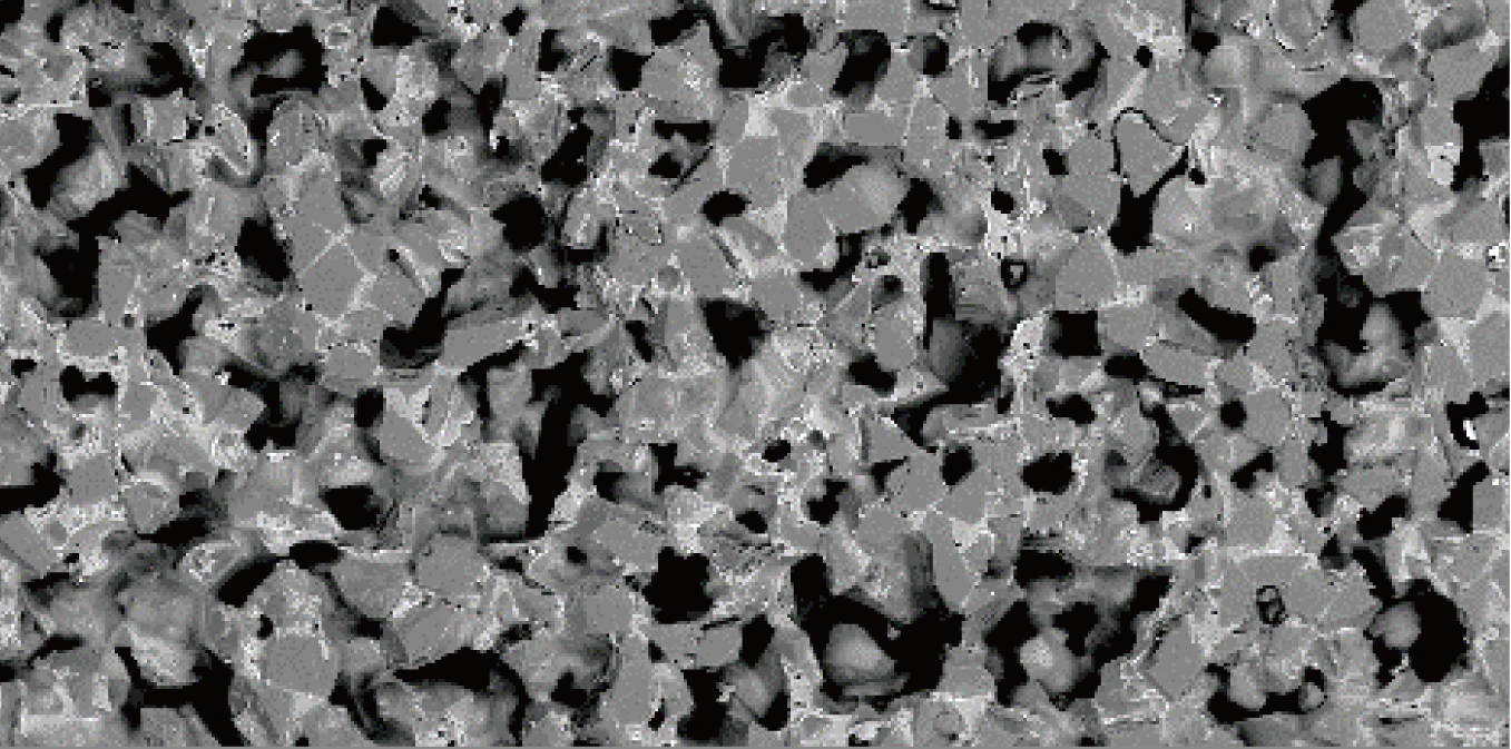
The micrographs contrast small, evenly distributed pores with a coarse pore structure. The CBN stone construction supports consistent machining. A sulphur-free design and more consistent performance with less scrap are further stated benefits; these are not converted into a general environmental lifecycle claim.
Taper roller bearing raceway: complete example
| Test parameter | Source specification |
|---|---|
| Workpiece / operation | Superfinishing a taper roller bearing raceway |
| Workpiece speed Vw | 100–200 rpm |
| Stock removal | 5 µm |
| Surface roughness | Ra 0.06 µm |
| Stone specification | B2400K120VHWPN |
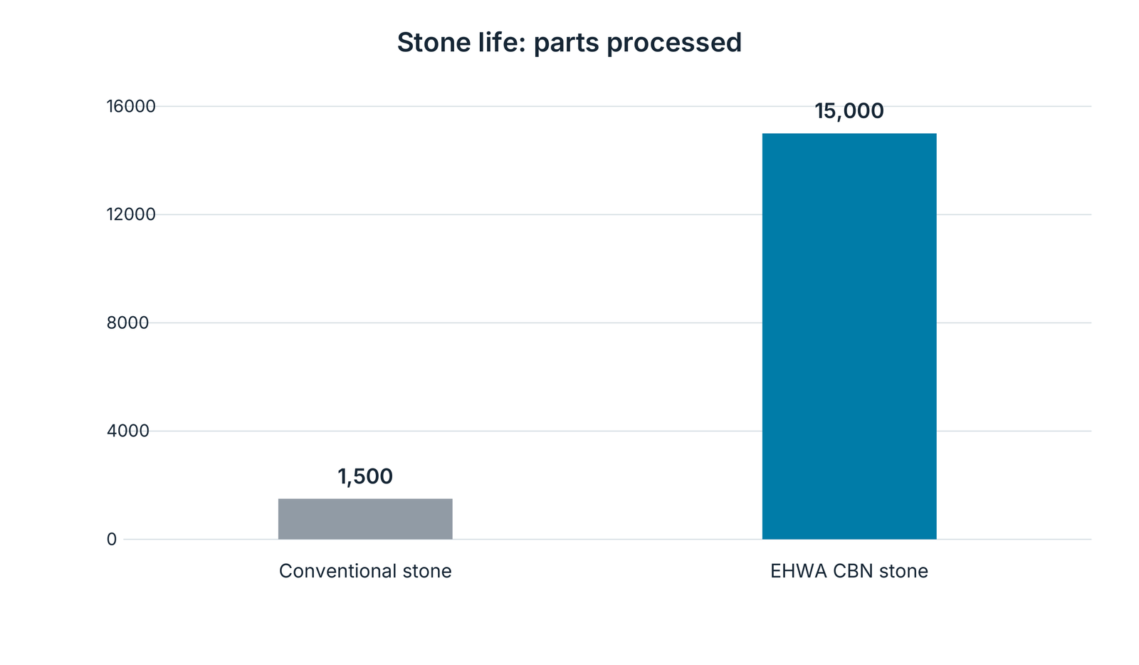
| Conventional stone life | 1,500 parts |
| EHWA CBN stone life | 15,000 parts |
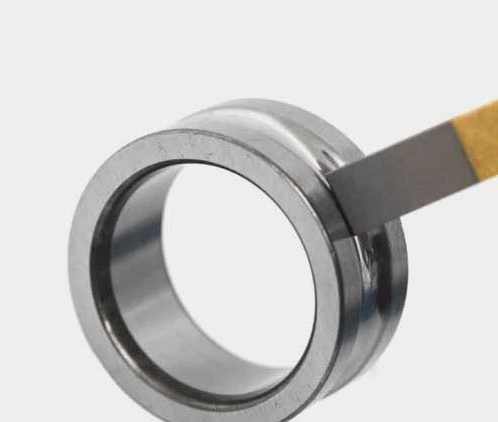
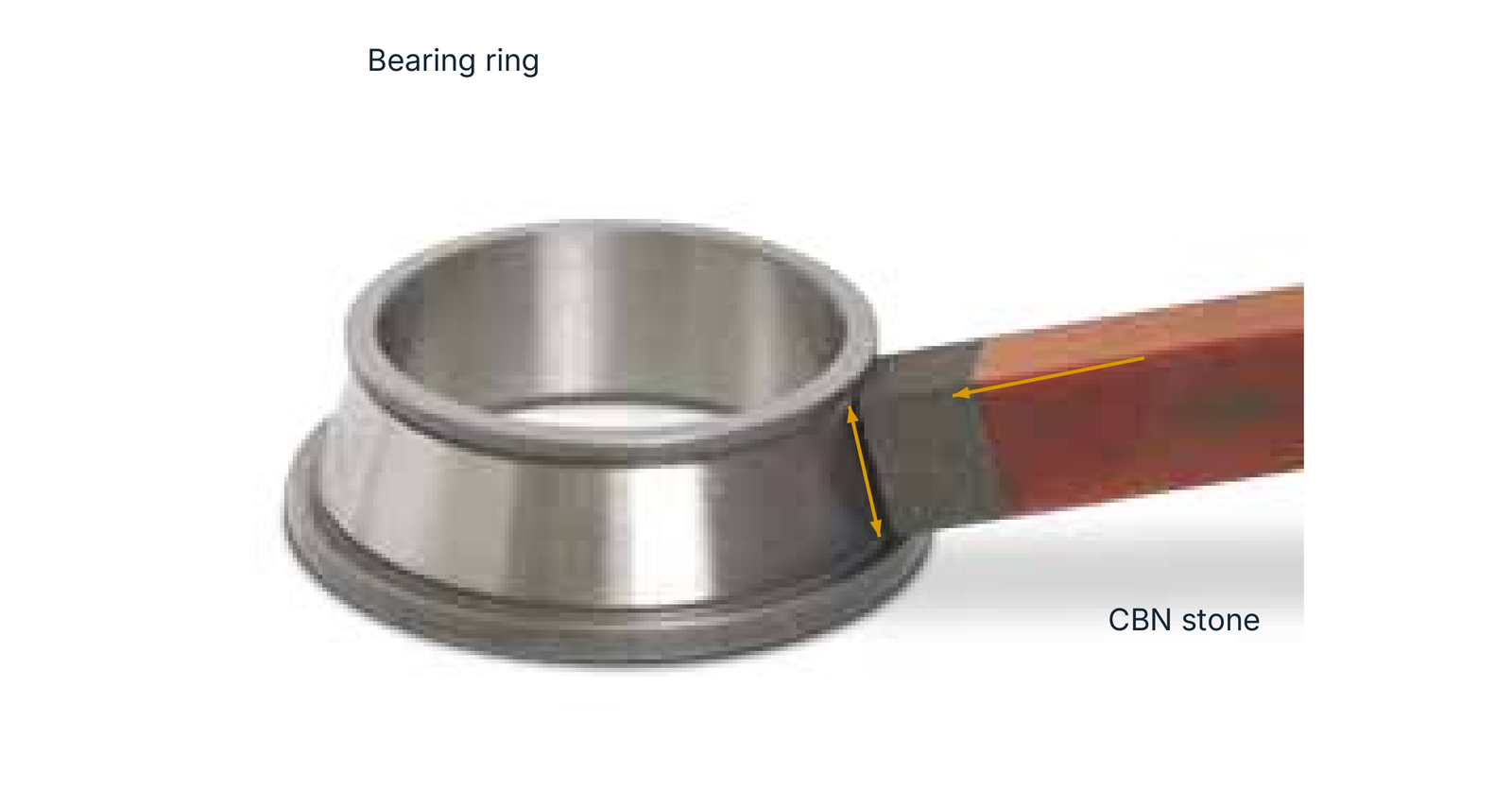
The source designates stone life as EA, the number of parts processed. The comparative values belong to this catalogue example; the source does not provide every test condition. The raceway/CBN stone contact is shown with the original movement directions.

Diamond rotary dressers for bearings
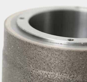
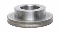
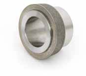
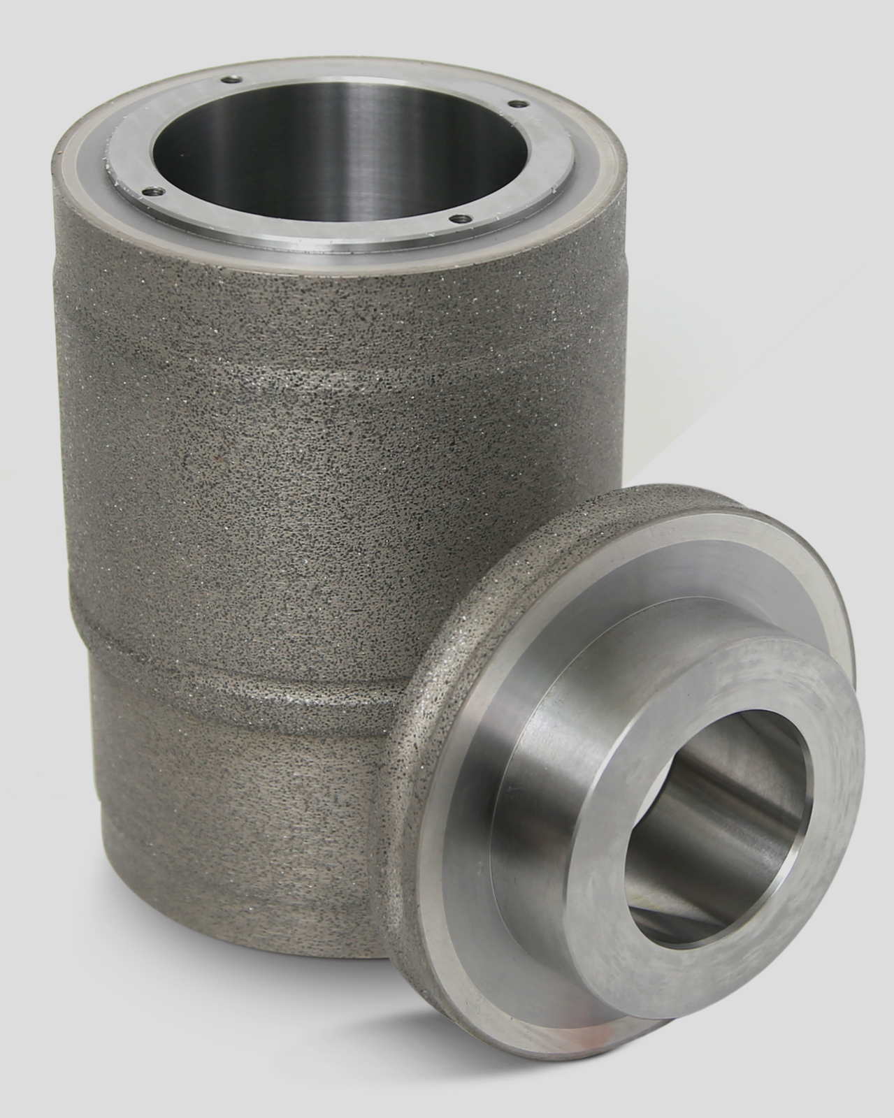
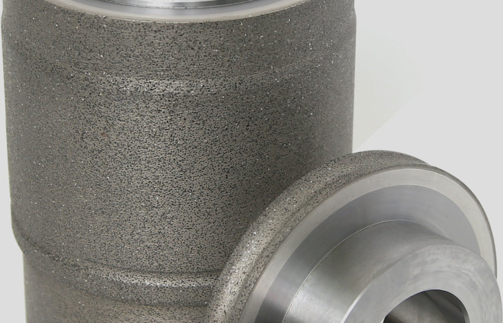
Diamond rotary dressers form and sharpen the grinding surface of vitrified CBN wheels. They support precise, complex contours with lower dressing loads, good dressing performance and long tool life. Shorter process cycles are a further benefit of the designs described in the sources.
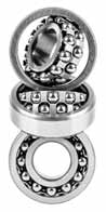
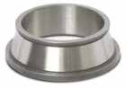
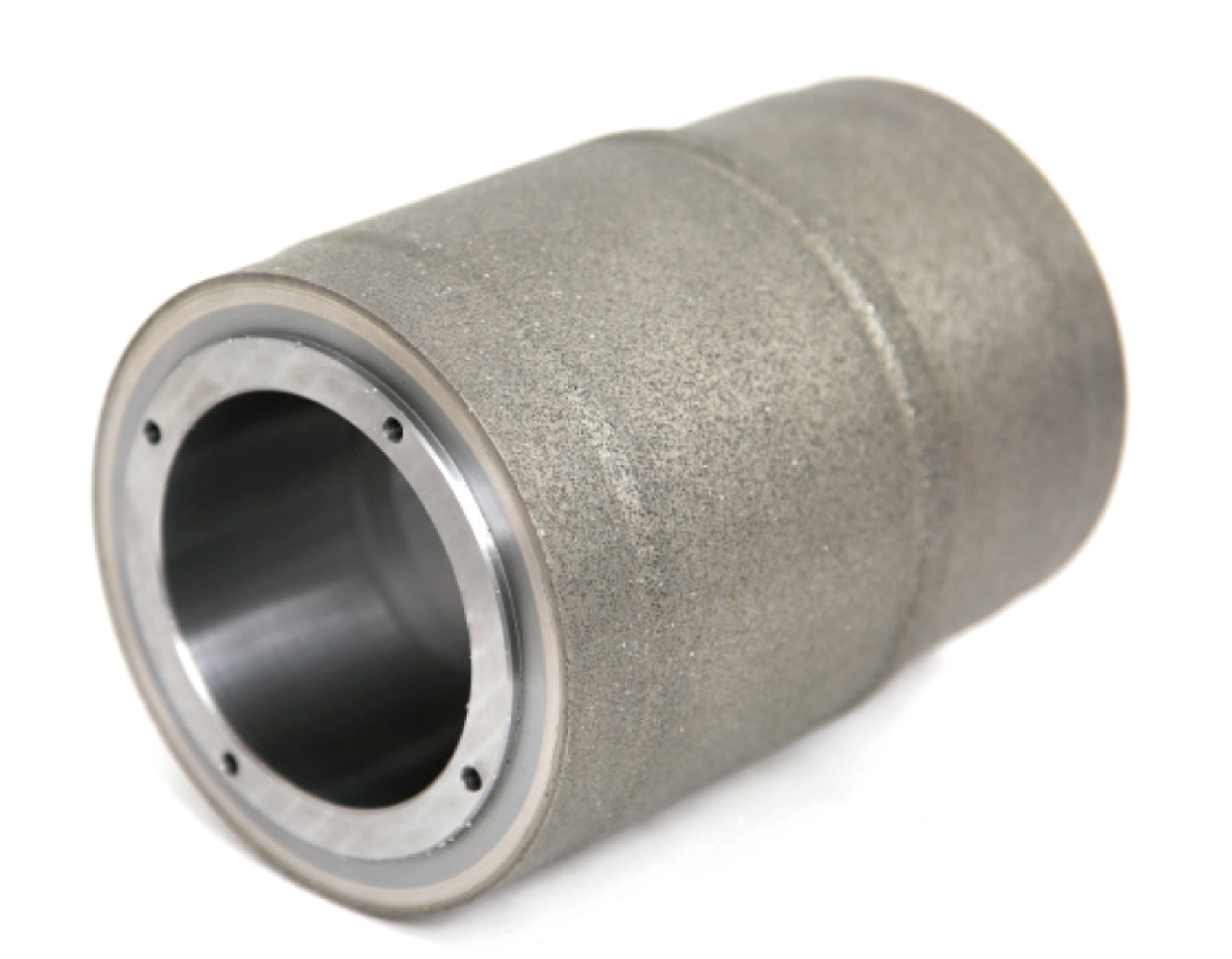
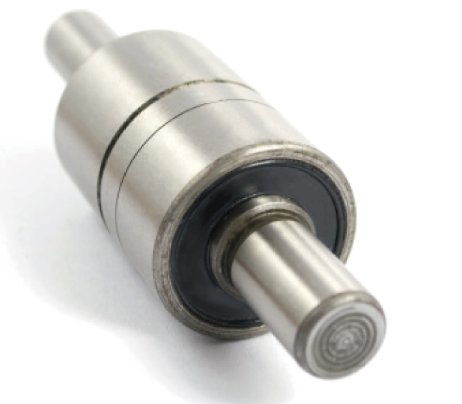
Applications include ball, roller and hub bearings and water pump bearings. Each source shows three specific tool/component pairs. Cylindrical and disc rotary dressers and their dressing layer details are retained as separate views.
| Application example | Tool and component pairing |
|---|---|
| Water pump bearing | Cylindrical rotary dresser and the illustrated bearing assembly |
| Ball bearing | Disc-shaped rotary dresser and ball bearing group |
| Taper hub bearing | Profile rotary dresser and the corresponding bearing ring |
Profile design follows the required grinding wheel contour. The illustrations show the geometrical variety of the range without assuming identical process values for every design.


Metal cup dressers for bearing internal grinding
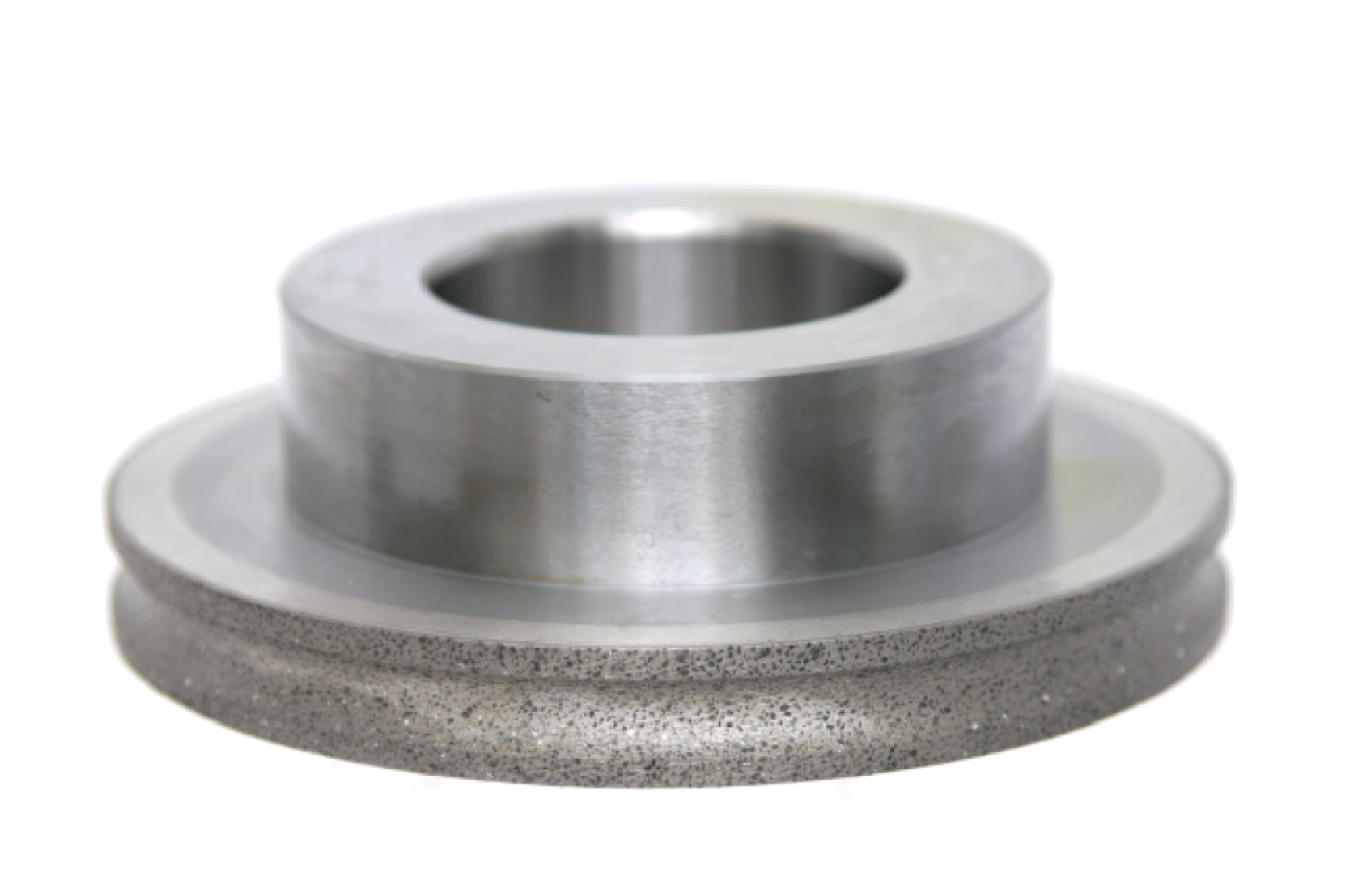
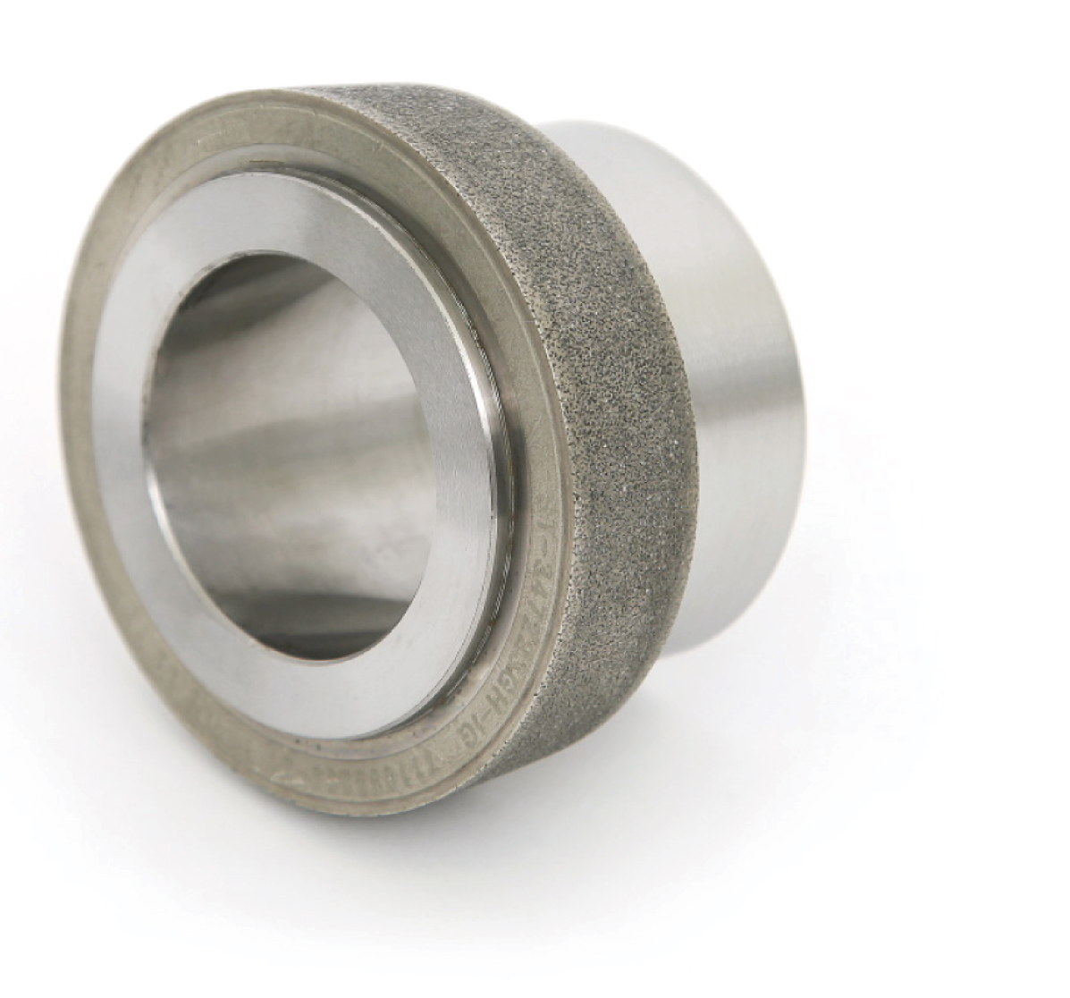
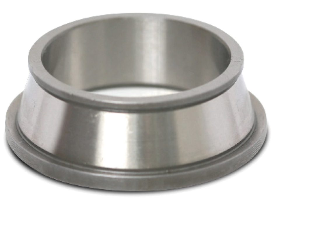
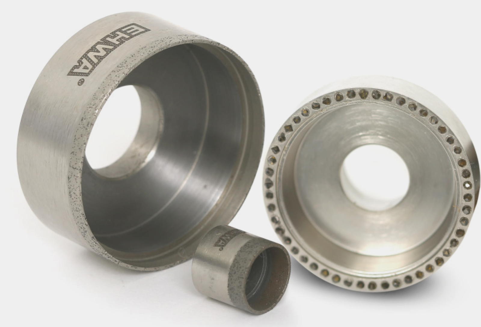
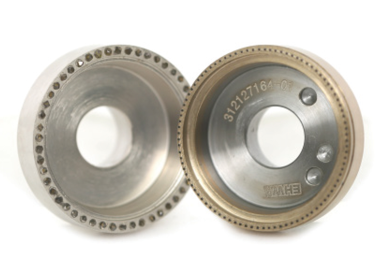
Metal cup dressers are intended for dressing tools used in bearing internal grinding. Precision dressing reduces grinding deviation after dressing. Longer dressing intervals and strong dressing performance support a stable manufacturing process.
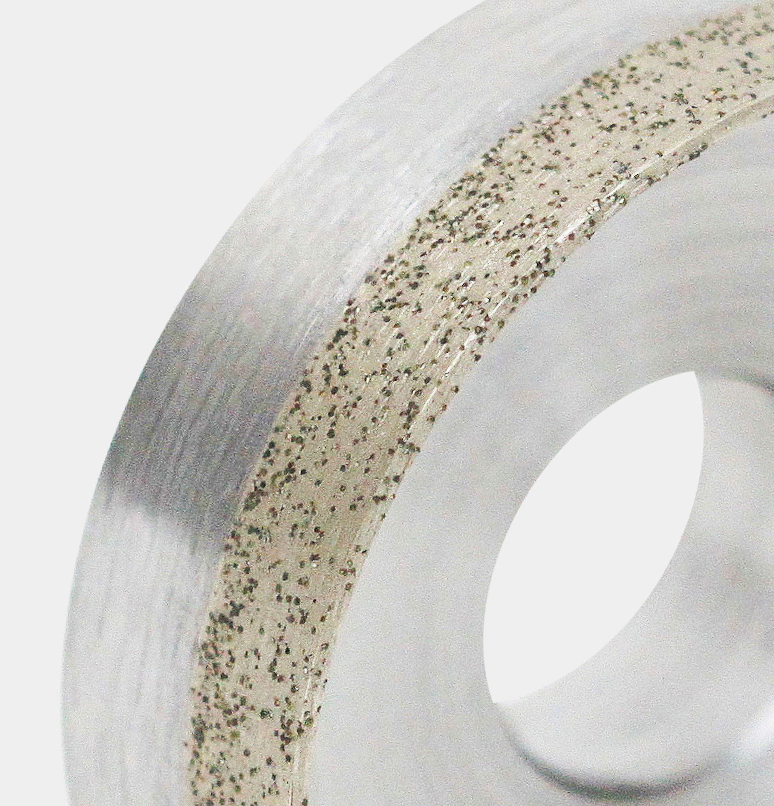
The source states a life of 20,000–30,000 operations depending on grinding wheel size. This relationship forms part of the specification: the count is not a uniform value for every wheel. The range includes metal cup dressers and rotary cup dressers with the dressing layer and construction variants shown.
Dressing layer width and process effect
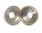
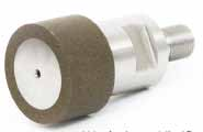
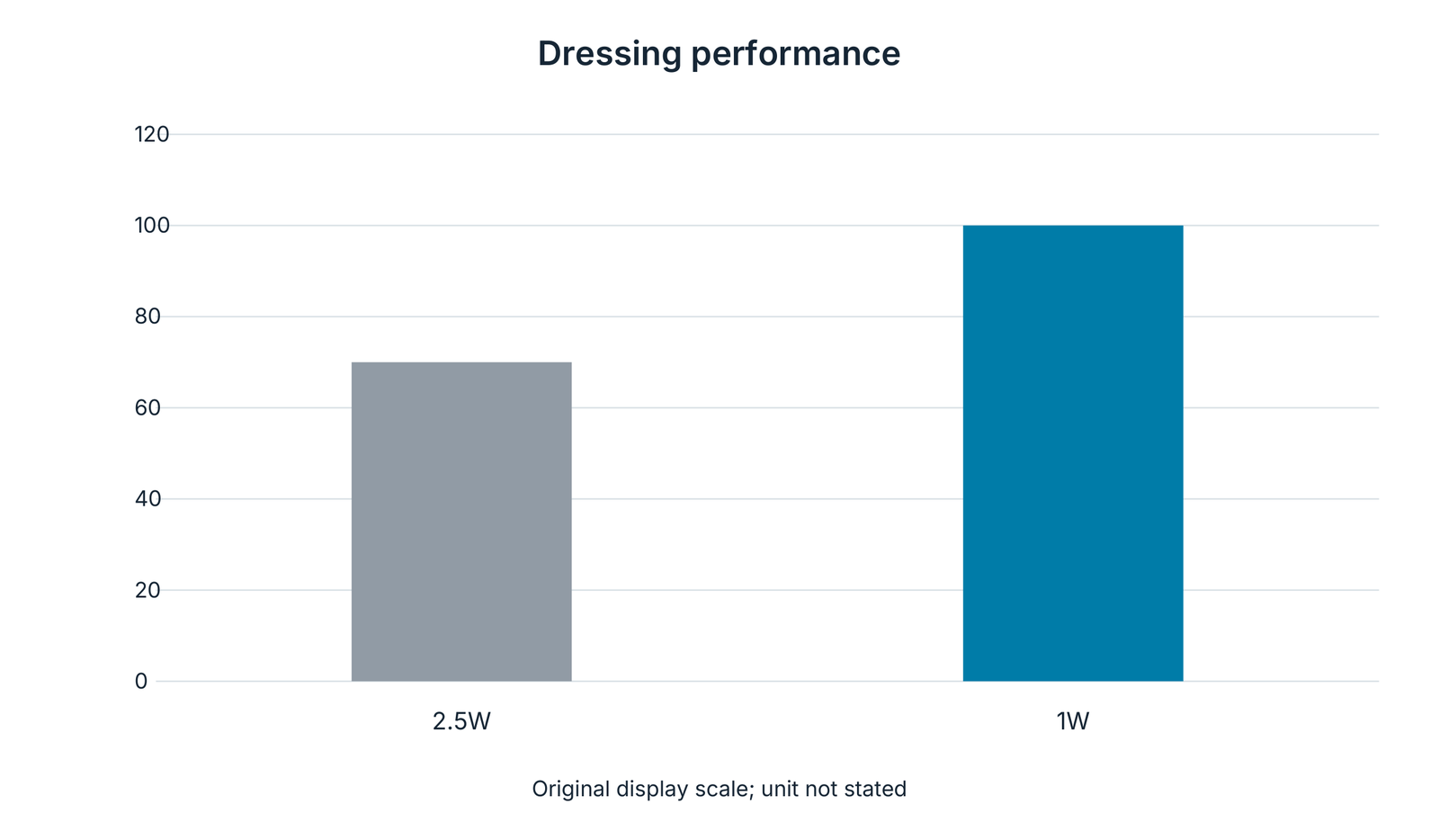
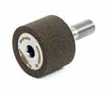
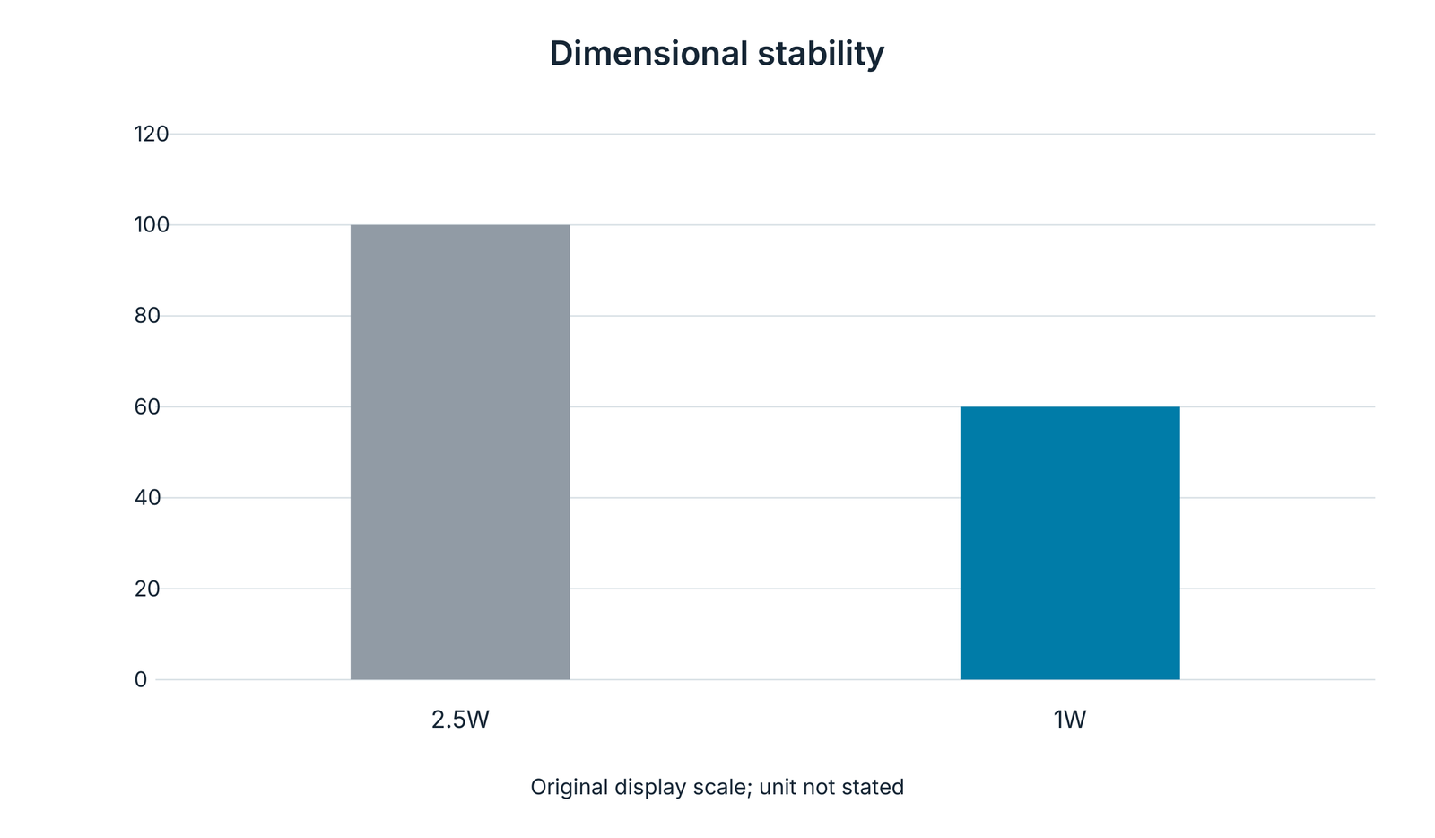
Two comparisons refer to vitrified wheels with a steel quill and a steel head respectively. They show dressing performance and workpiece dimensional stability against tip or diamond layer width. The sources identify the variants as 2.5W and 1W.
Both diagrams retain the original 0–120 display scale and bar relationships. The source provides no physical unit for these scales; the illustrations compare the designated width variants. Dressing performance and dimensional stability are therefore considered separately.





Face and double-disc grinding of bearing components
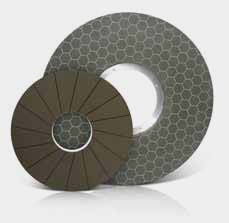
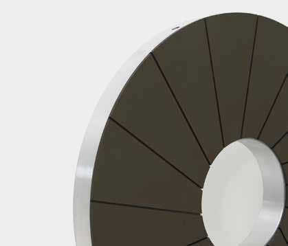
Face and double-disc wheels grind the end faces of bearing rings and rollers. The EHWA designs target higher productivity, shorter cycles, lower machining costs and long wheel life. End-face surface finish is an essential selection objective alongside stock removal performance.
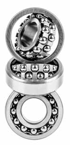
The range shows different grinding surfaces, including a honeycomb design and a radially segmented design. Applications cover needle bearing rollers, roller bearing rollers and inner and outer rings. The bearing photographs relate the operation to real component families.
| Component family | Grinding surface | Stated benefit |
|---|---|---|
| Needle bearing rollers | Roller end faces | Short machining cycles |
| Roller bearing rollers | Roller end faces | Tool life and surface finish |
| Inner and outer rings | Ring end faces | Productivity and consistent face grinding |
The wheel forms shown support selection by component geometry and machine process.
Horseshoe wheels for taper roller end faces
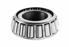
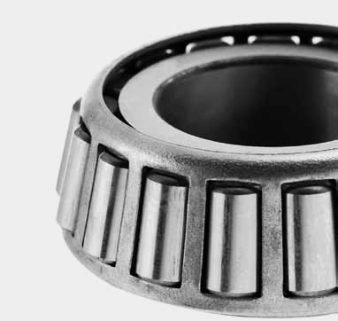
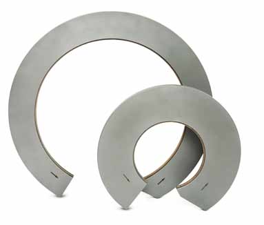
The open, horseshoe-shaped grinding wheel is intended for taper roller end-face grinding. The source shows a main design with a taper roller bearing and two further open wheel forms. Stated benefits are longer tool life and cost savings, higher removal rates and good surface finish.
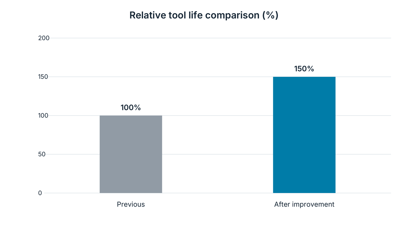
The tool life comparison shows the previous design at 100% and the improved design at 150%. This is a relative comparison for the catalogue case shown. The original chart title is “Tool life (pcs)”, while the bars are labelled as percentages; no absolute part counts are inferred.

Profile rotary dressers for linear guides
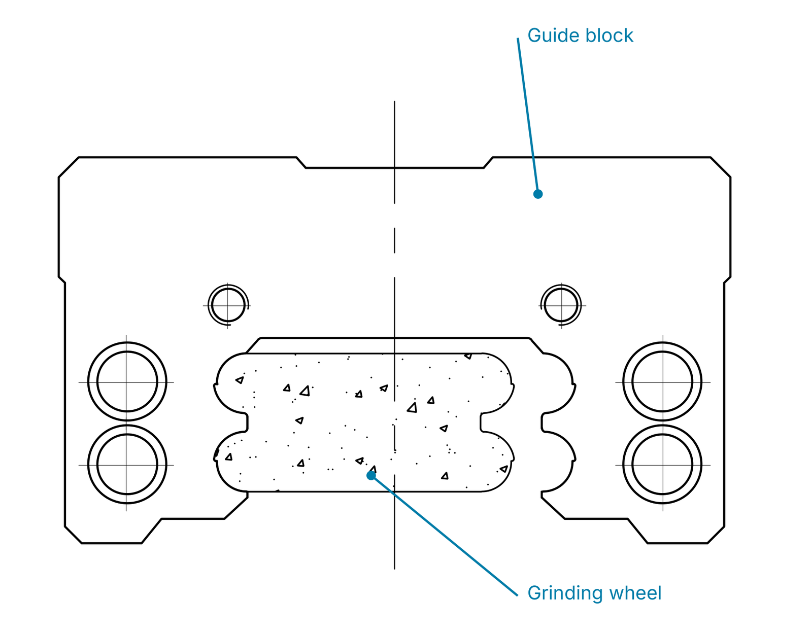
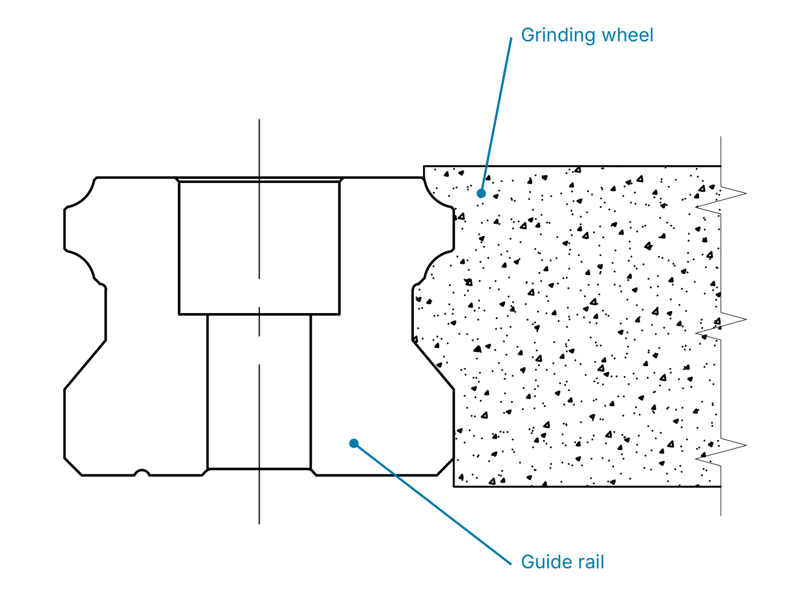
A linear guide consists of a guide block, rail and recirculating balls between them. It provides precise linear motion; the source names automotive manufacturing equipment as an application. The ball raceway seats in the block and rail require matching contours.
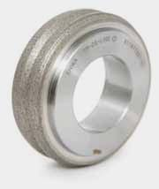
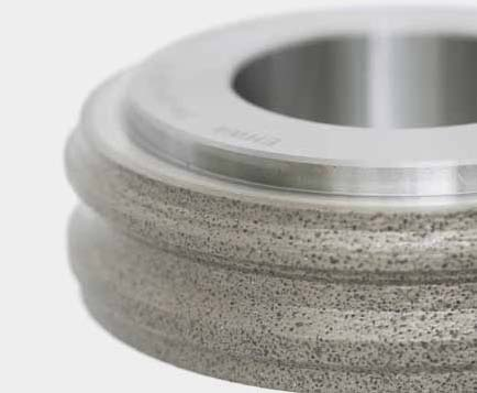
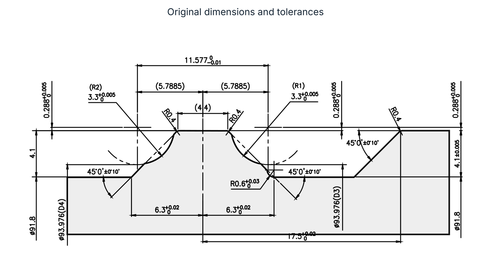
Diamond rotary dressers profile the CBN grinding wheel used to machine these ball raceways. The catalogue distinguishes block and rail designs. Each design has a tool photograph, a complete dimensioned profile drawing and a separate wheel/component contact illustration.
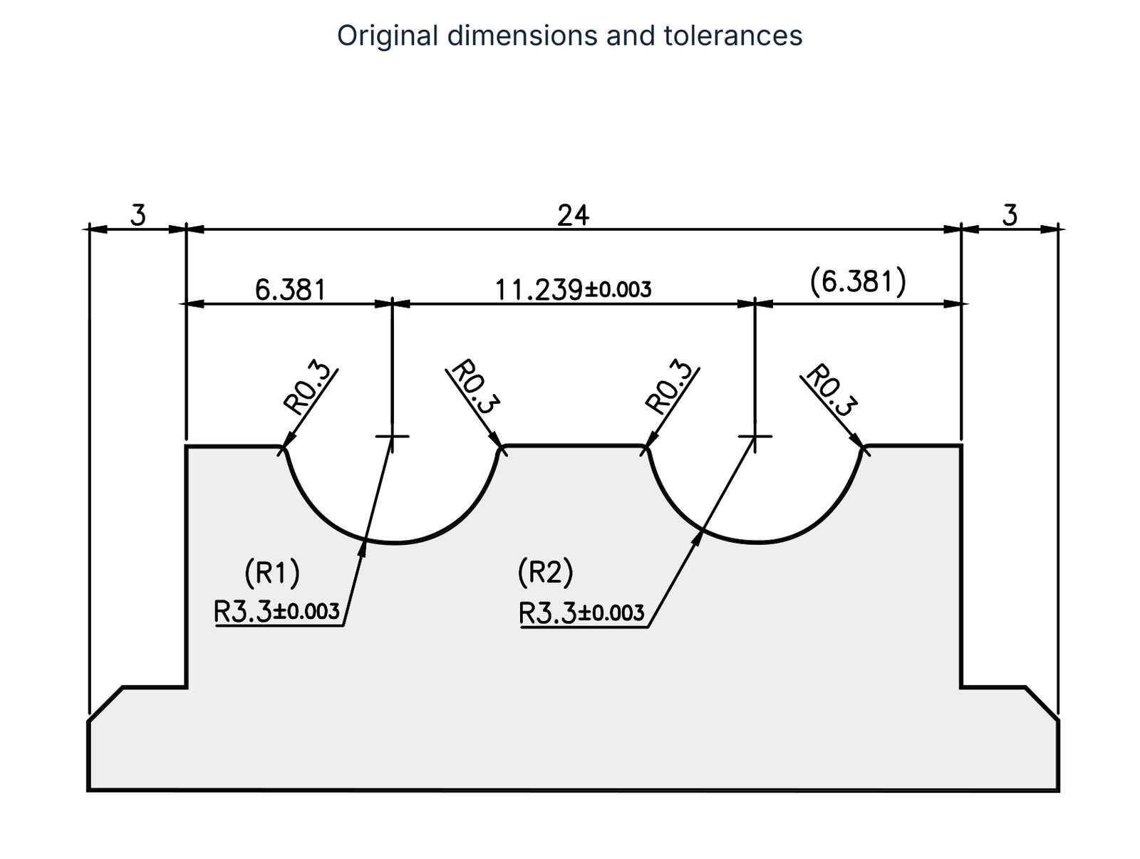
Guide block: profile drawing
The original dimensions include widths 3 / 24 / 3, spacing 6.381 / 11.239±0.003 / (6.381), four R0.3 transitions and the two radii (R1), (R2) at R3.3±0.003. The drawing retains these values with all dimension lines and positional relationships.
Guide rail: profile drawing
The second drawing includes 11.577 with +0/−0.01 tolerance, the two reference dimensions (5.7885), (4.4), R0.4, radii (R1)/(R2) 3.3 with +0.005/0 and R0.6 with +0.03/0. Further width, height, diameter and angular tolerances are retained completely in the drawing. The 45° angles with ±0°10′ belong to this rail profile.
Dimensions remain as shown in the source drawings. No general unit is printed within these drawing details; the approved component drawing determines the unit, datum system and tool contour.
Profile rotary dressers for ball screws
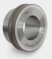
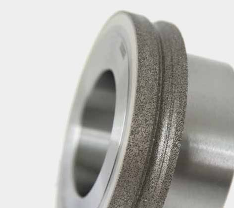
A ball screw converts rotary motion into linear motion. Screw, nut and balls form the functional assembly. The EHWA rotary dressers combine high diamond concentration with precision dressing and long life.
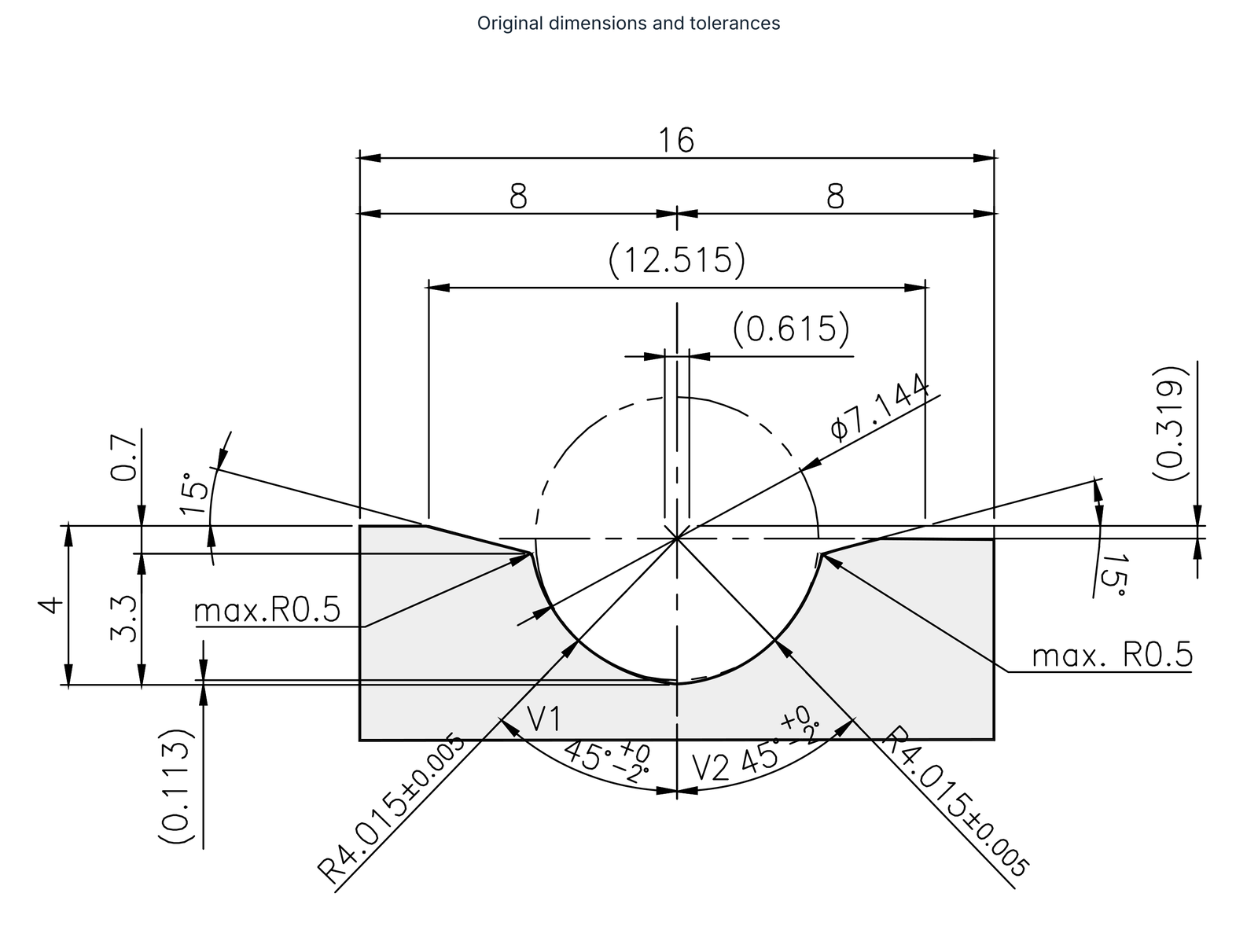
The illustrated R-profile retains its complete technical drawing: overall width 16, the two partial widths 8, reference dimensions (12.515), (0.615), (0.319), (0.113), diameter Ø7.144, heights 0.7 / 4 / 3.3, 15° angles on both sides, max. R0.5 and both R4.015±0.005 radii. The 45° angles designated V1 and V2 have an asymmetric tolerance of +0/−2°. These angles differ from the guide rail drawings in the preceding chapter.
The drawing preserves the location and direction of every dimension. As with the linear guide profile, no general unit is printed within the detail. The complete component drawing and required raceway geometry govern tool design.
CBN grinding tools for CV joints
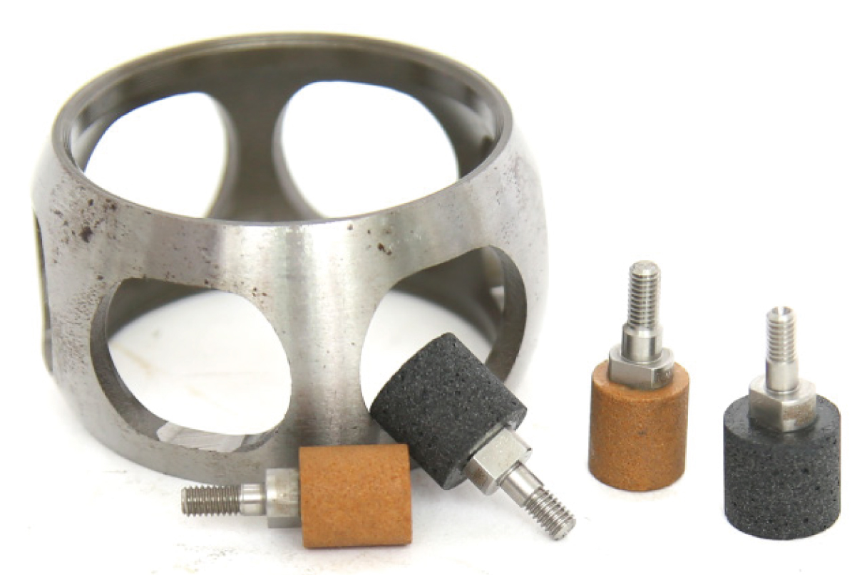
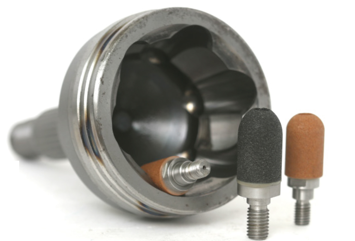
CV joints require different functional surfaces to be machined. The vitrified CBN designs in the second document target high removal rates for increased production capacity, good surface quality with low thermal load and tight tolerances. Longer dressing intervals and reduced wheel wear can lower machining costs and improve process consistency.
The source distinguishes two specific applications and specifications:
| Grinding case | Standard specification | Associated illustrations |
|---|---|---|
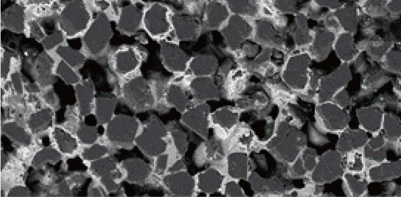
| Cage window grinding | B126M180VBTM | Cage, tool designs and CBN microstructure |
| Outer race grinding | B181M160VBTM | Outer race, tool designs and vitrified wheel pore structure |
Tool geometry and microstructure are selected for the particular component area. The two specifications remain separate because cage windows and outer races represent different grinding tasks.

Injector bore and seat grinding
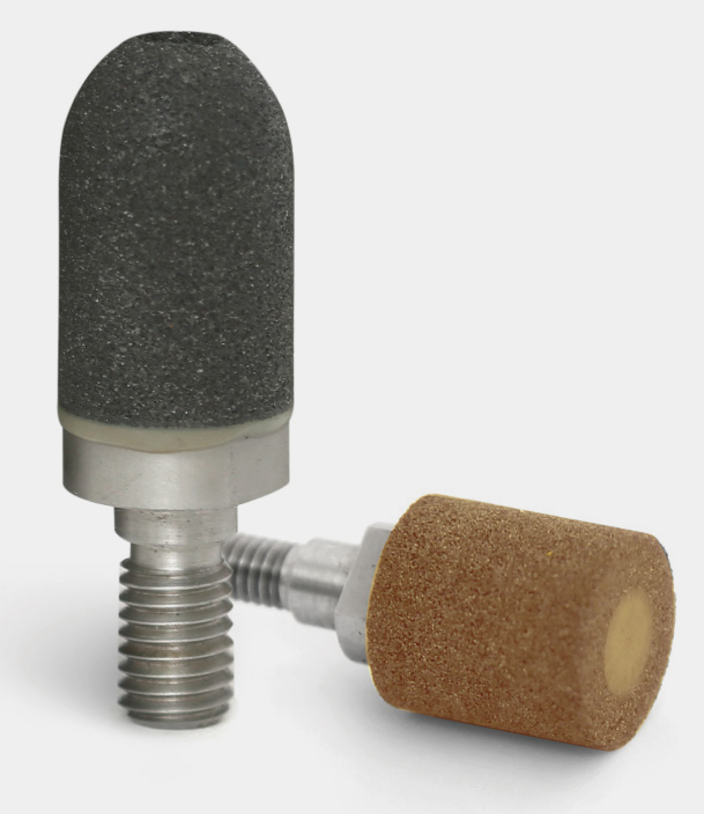
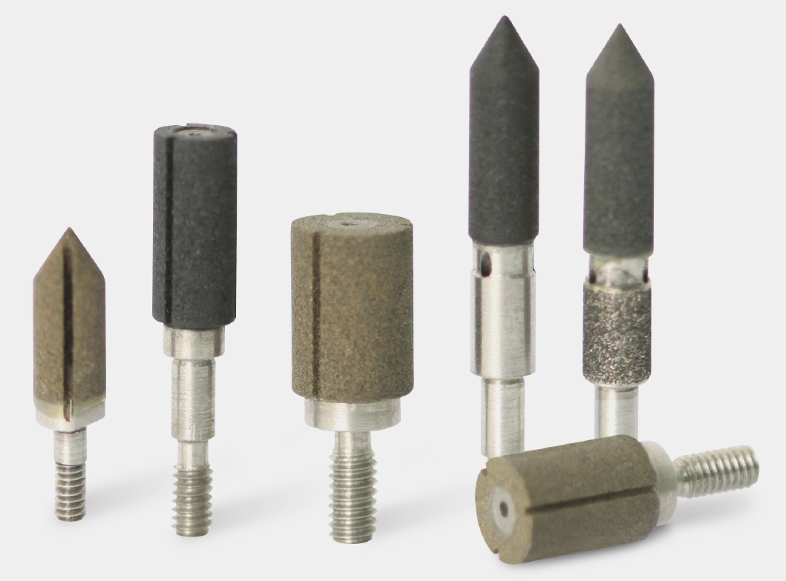
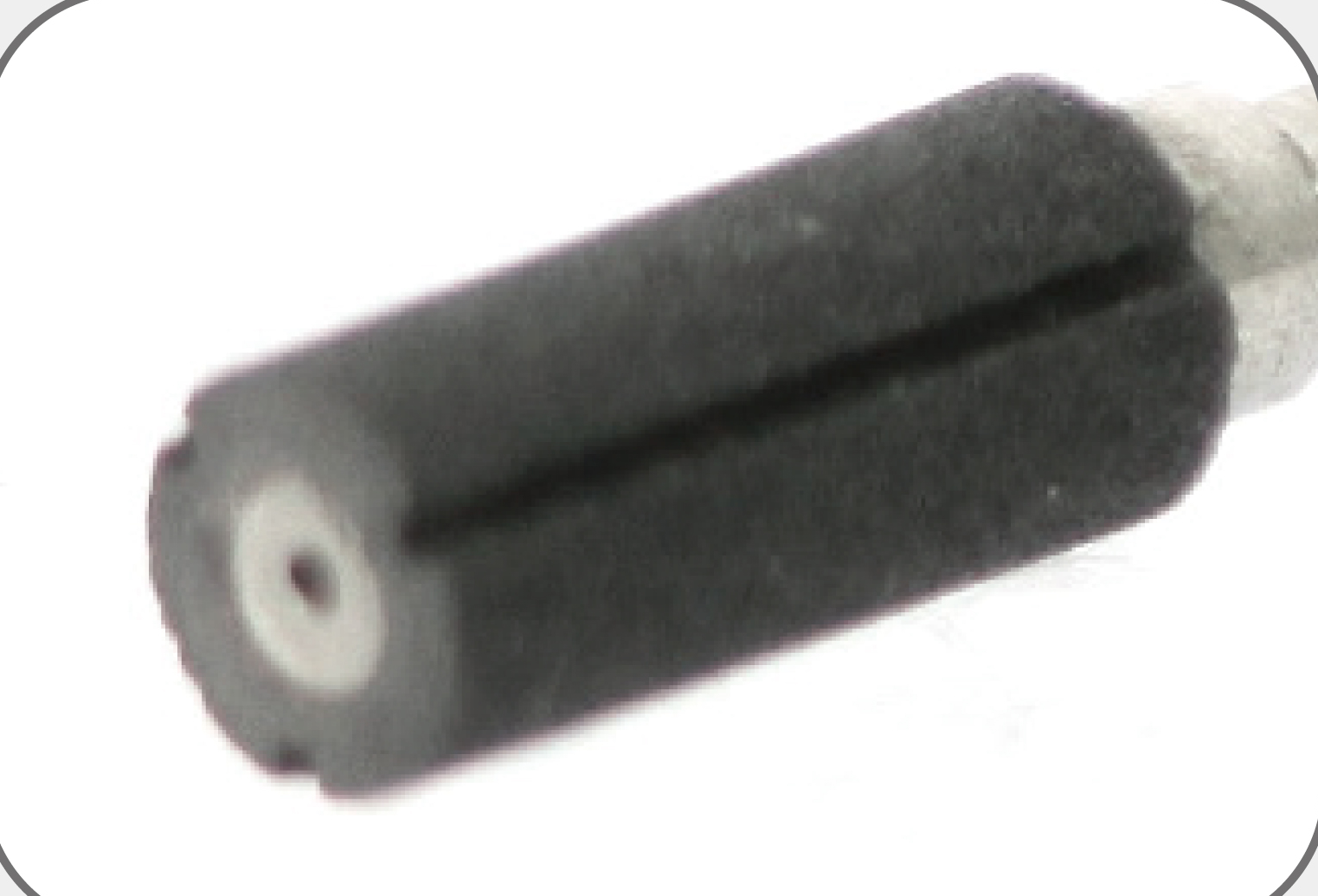
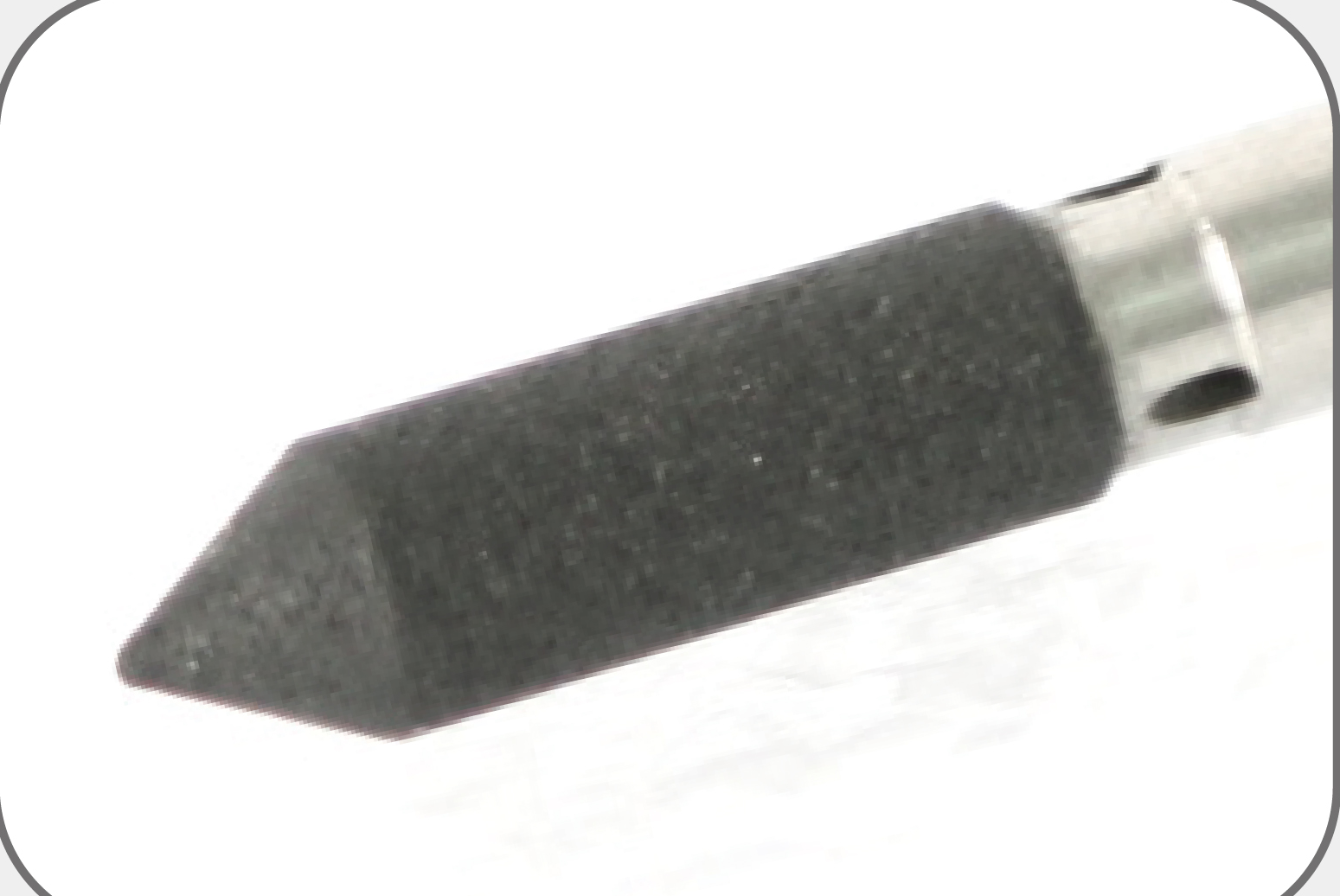
For injector components, EHWA shows cylindrical bore grinding tools and pointed seat grinding tools. Coolant holes and slots form part of the tool geometry. Free-cutting abrasive, longer dressing intervals, more efficient tool utilization and consistent grinding performance are the stated benefits.
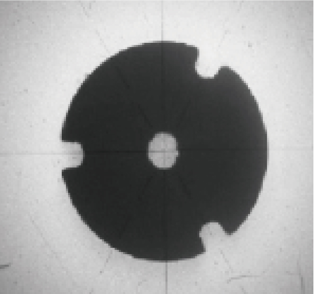
The precise shape includes the coolant hole and slots. End and side views make this geometry visible; the complete standard specifications appear in the table.
| Specification feature | Source specification |
|---|---|
| Grinding operation | Bore and seat |
| Coolant hole size | H 0.5–1.0 mm |
| Grinding tool size | D 1.5–20 mm |
| CBN grit size | 29–76 µm |
| Slot | 0.4–1.5 mm |
H and D remain as the source designations. The particular tool design follows the bore, seat, mounting and coolant supply requirements.
Related range: porous hybrid bond for rotary tools
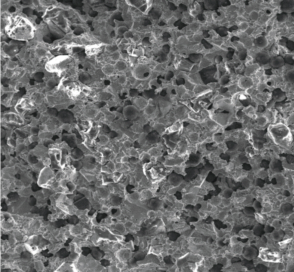
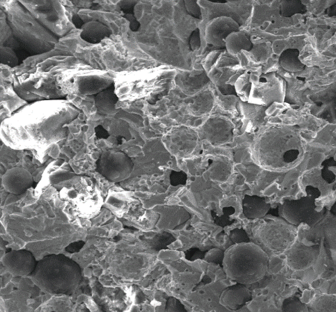
The porous hybrid bond combines an open structure with strong grinding performance. It supports abrasive protrusion and coolant flow and can therefore reduce grinding load. Higher permissible feed rates enable shorter cycle times. Further benefits are high stock removal, reduced residual stress and thermal damage, high dimensional stability, good surface finish and edge quality, long dressing intervals and low power consumption.
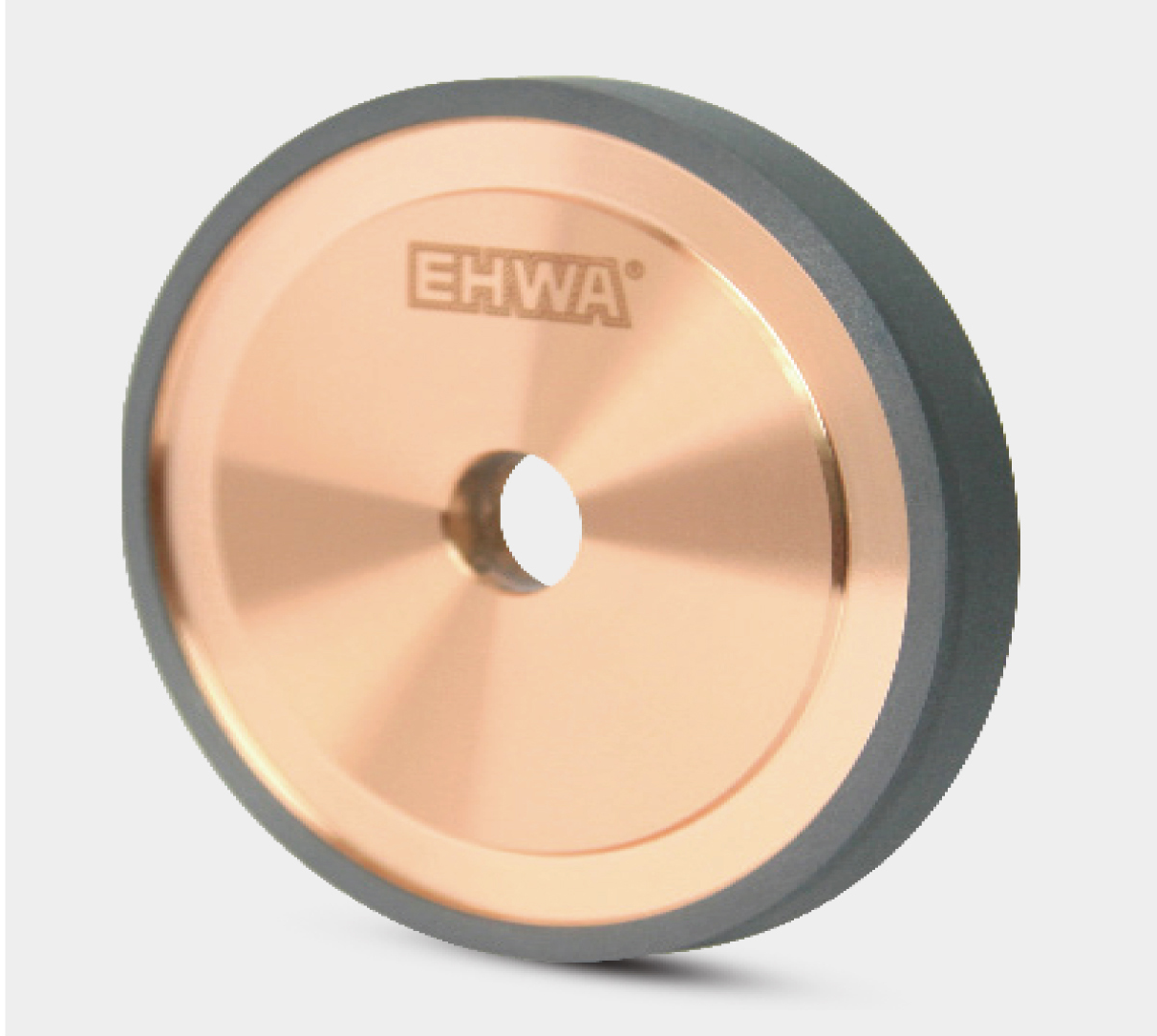
Applications include fluting tungsten carbide drills and end mills, gashing tungsten carbide drills and clearance angle grinding. The source shows two micrographs and wheel shape 1A1.
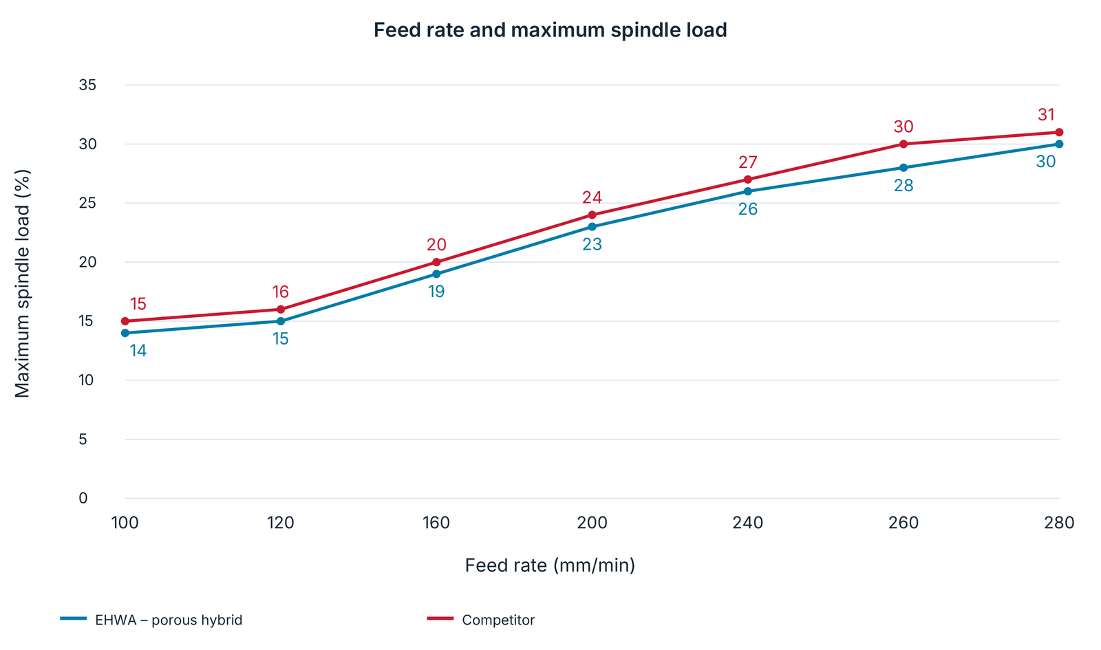
Test on ANCA MX7 Linear
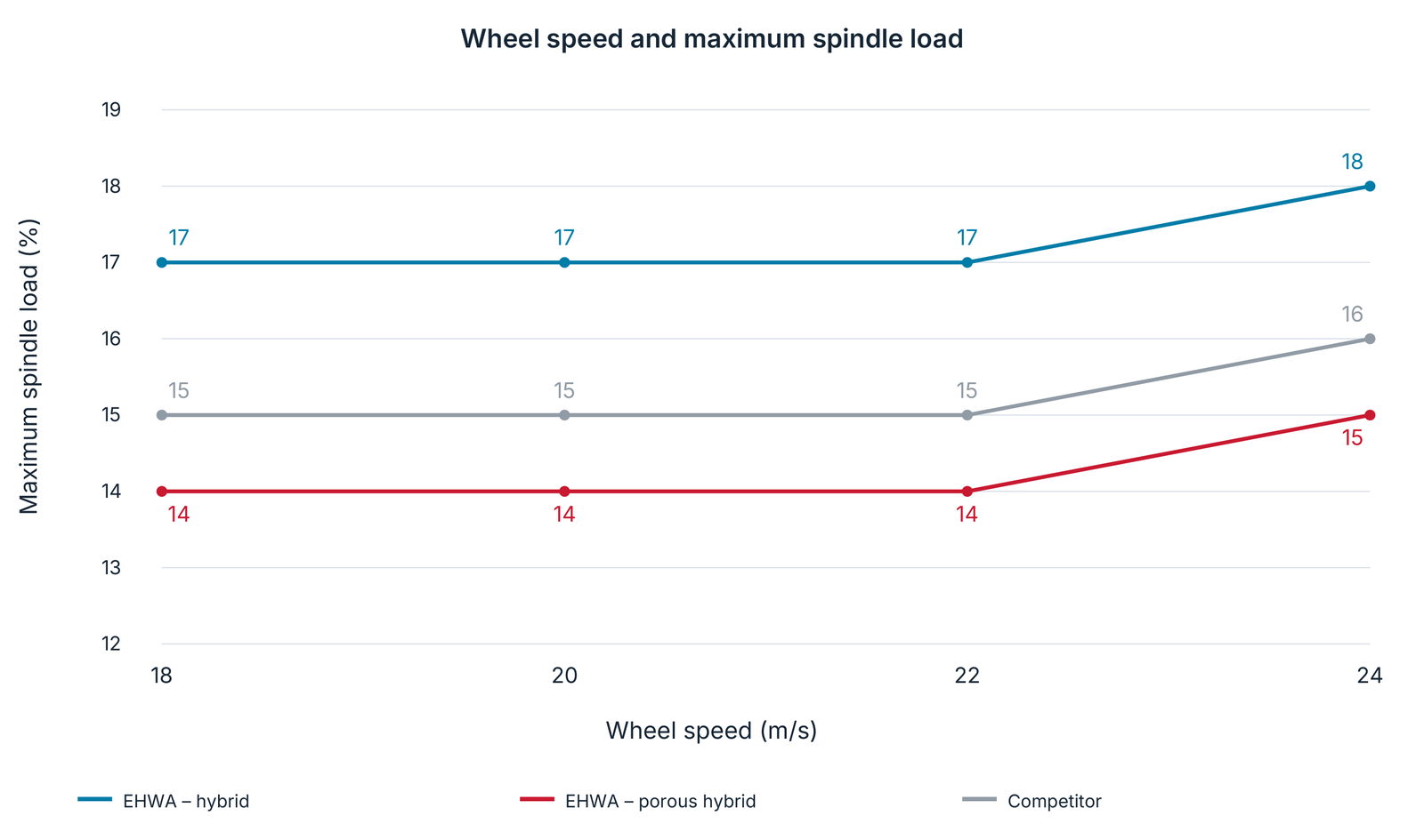
Specification: D54 Porosity hybrid bond. Both charts belong to this test and show maximum spindle load as a percentage.
| Feed rate (mm/min) | EHWA – porous hybrid: maximum spindle load (%) | Competitor: maximum spindle load (%) |
|---|---|---|
| 100 | 14 | 15 |
| 120 | 15 | 16 |
| 160 | 19 | 20 |
| 200 | 23 | 24 |
| 240 | 26 | 27 |
| 260 | 28 | 30 |
| 280 | 30 | 31 |
| Wheel speed (m/s) | EHWA – hybrid (%) | EHWA – porous hybrid (%) | Competitor (%) |
|---|---|---|---|
| 18 | 17 | 14 | 15 |
| 20 | 17 | 14 | 15 |
| 22 | 17 | 14 | 15 |
| 24 | 18 | 15 | 16 |
The curves explicitly distinguish the conventional EHWA hybrid bond and the EHWA porous hybrid bond. The values are presented as test data and are not transferred to other machines or tools.
Related range: diamond wheels for micro tools
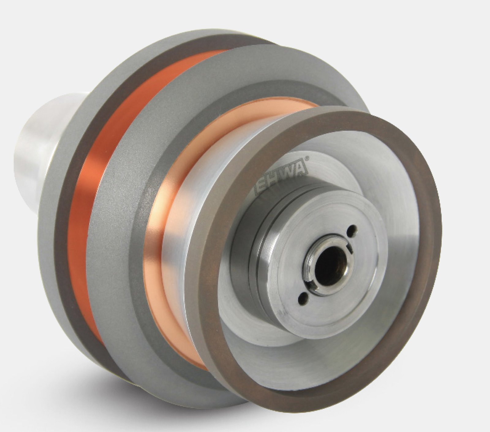
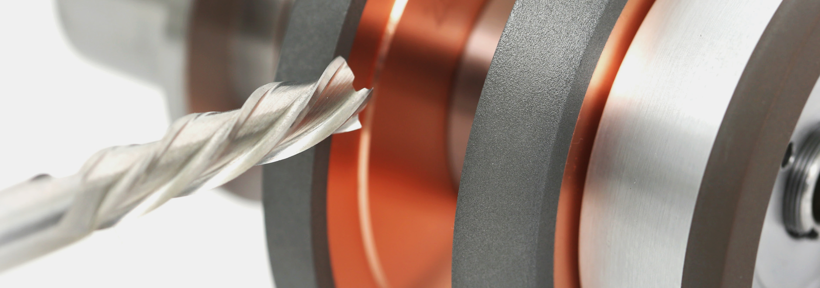
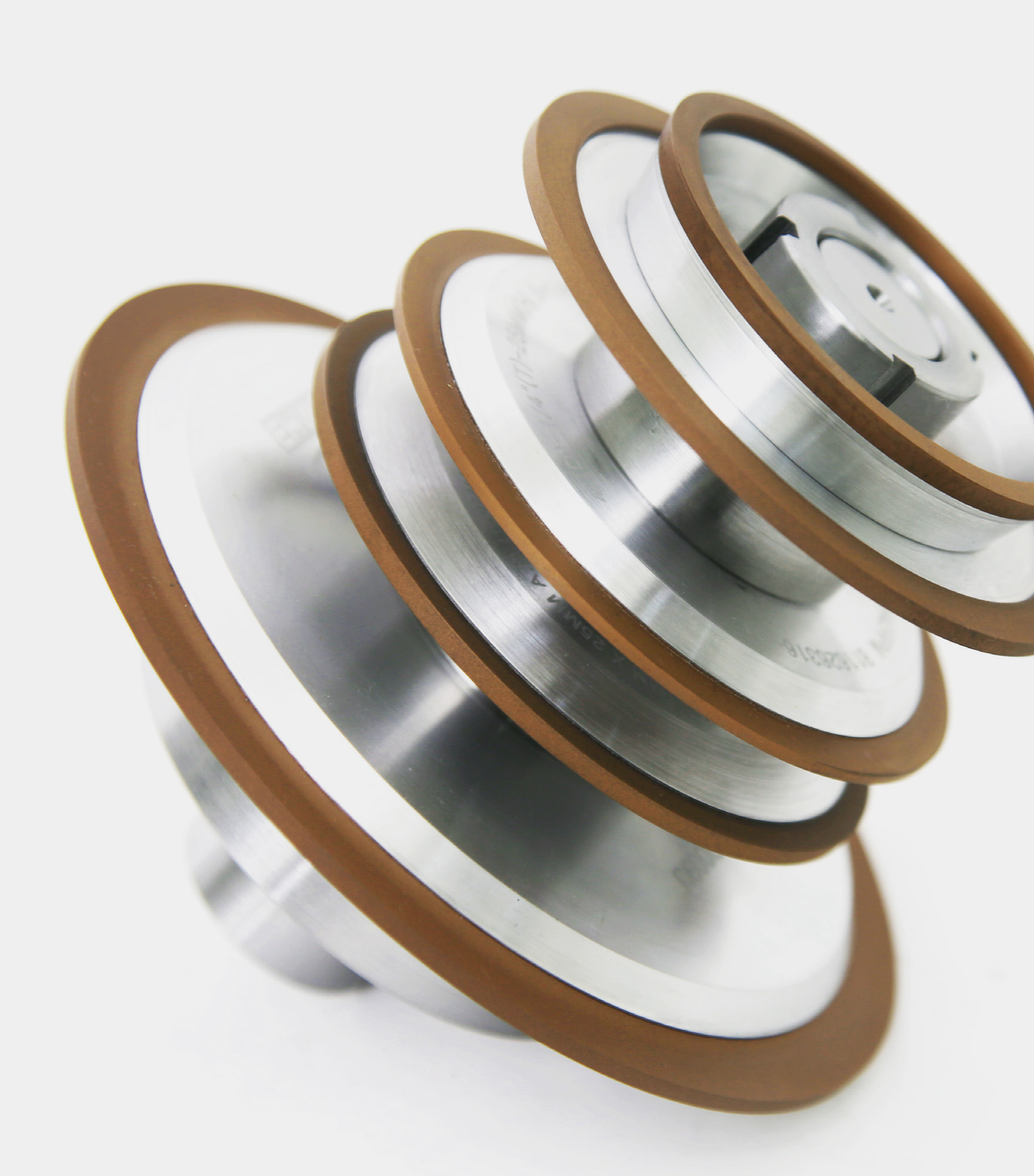
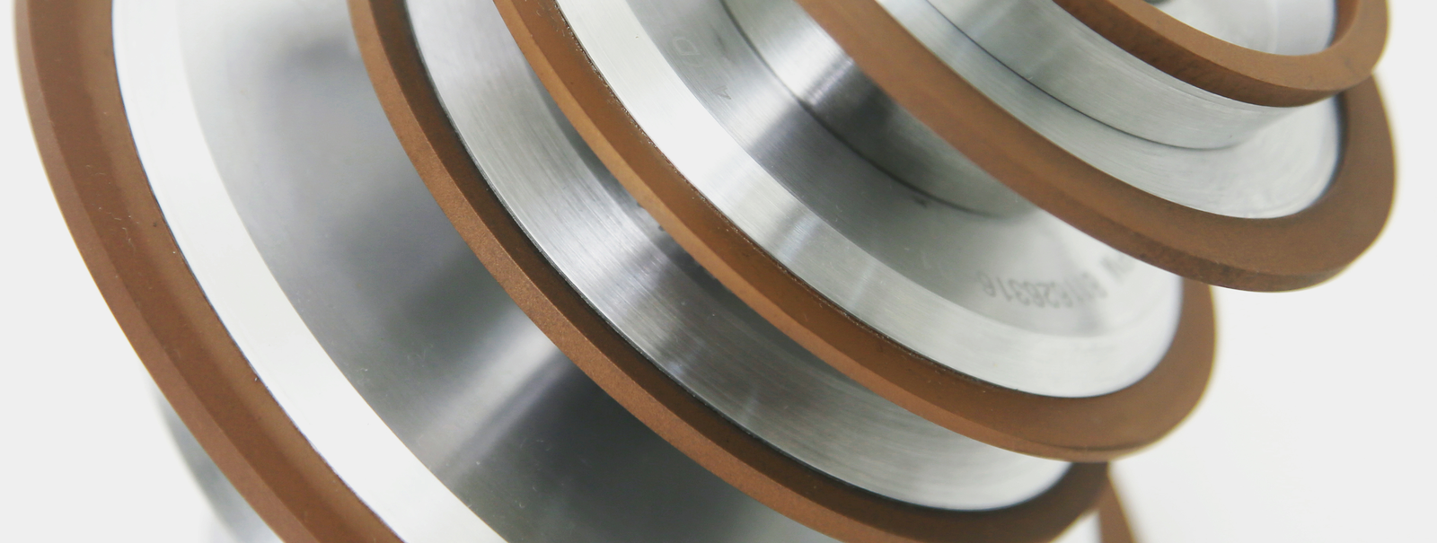
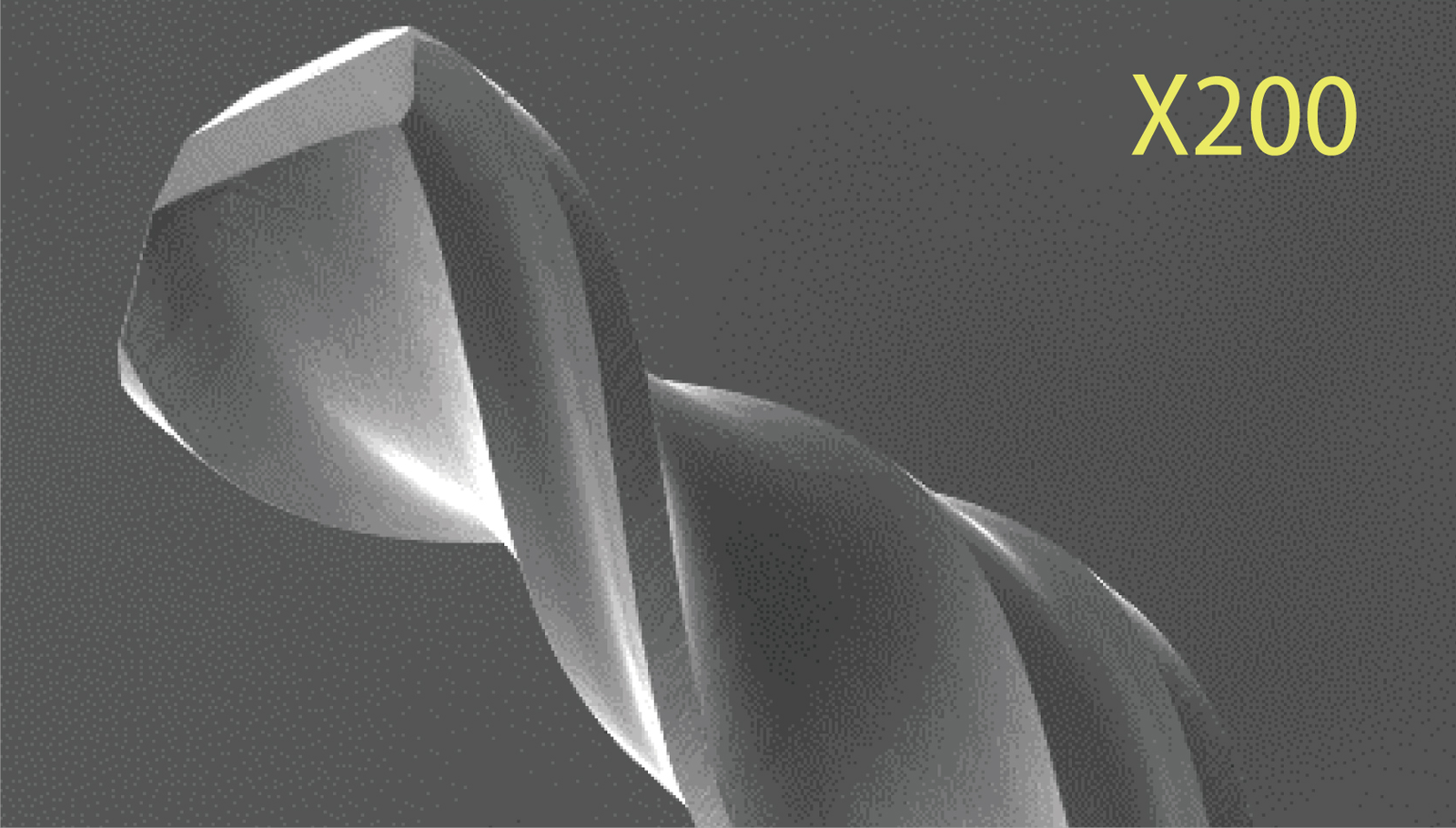
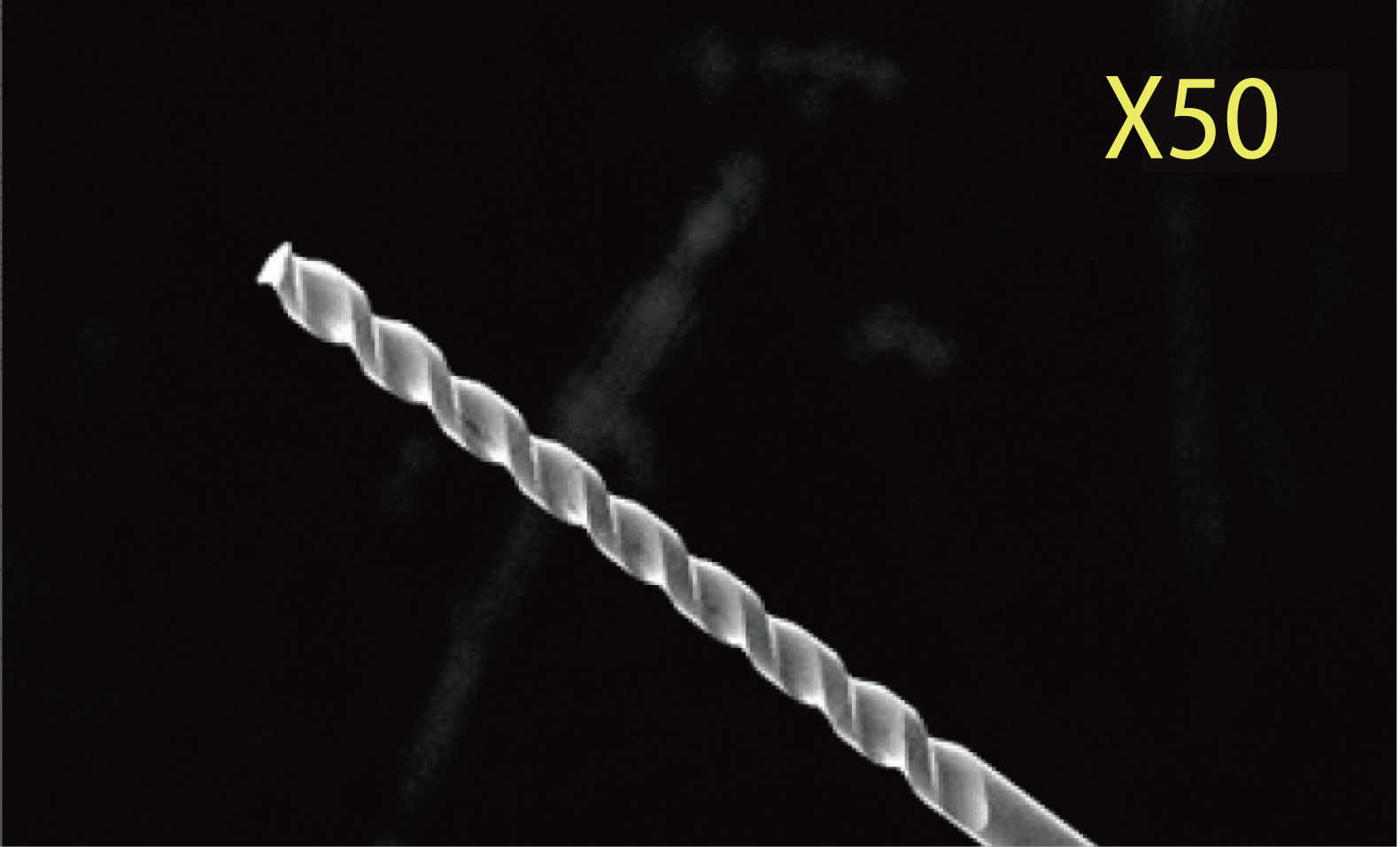
Micro drills, micro end mills and router bits require clean cutting edges and precise geometry. EHWA grinding wheels target high productivity and low tooling cost. The source states strong heat resistance, improved surface and edge quality, and precise dimensional and cutting edge stability.
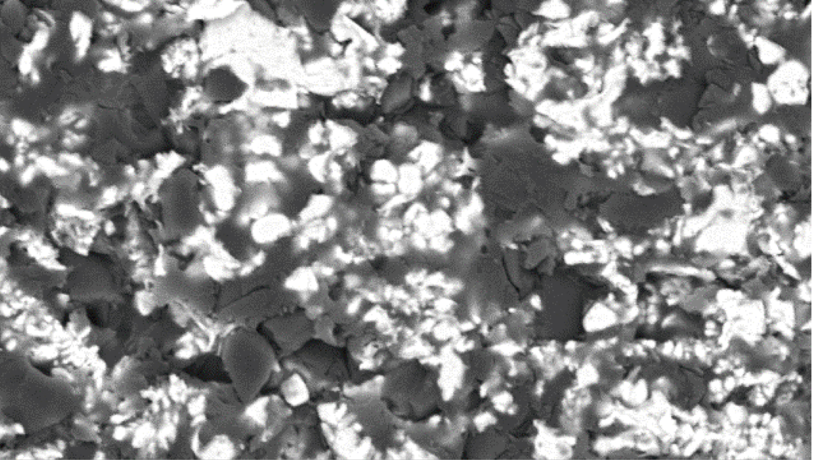
The range shows hybrid bond and high-performance polyimide bond with separate micrographs. For manufacturing micro rotary tools, the source names machines from ROLLOMATIC, ANCA and WALTER, among others. Two photographs of real micro cutting tools retain their original magnification markings X200 and X50.
| Application / design | Association |
|---|---|
| Micro drills, micro end mills, router bits | Rotary micro cutting tools |
| Hybrid bond | The illustrated porous microstructure |
| High-performance polyimide bond | Separate micrograph for the thermally stable bond family |
| X200 / X50 | Original magnification markings on the tool photographs |
Tool selection combines grinding geometry, bond and the requirements for cutting edge and surface quality.
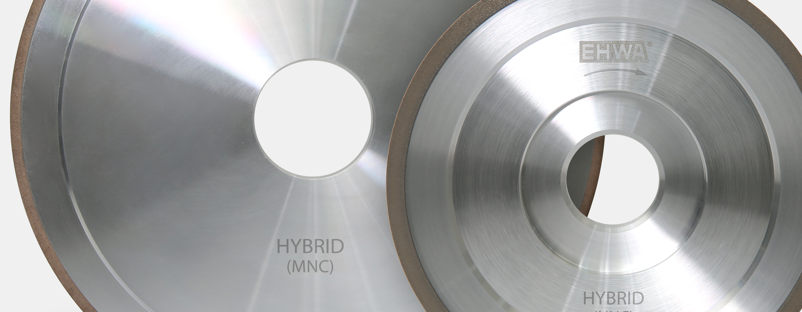
Related range: MNC hybrid bond and MEViOUS
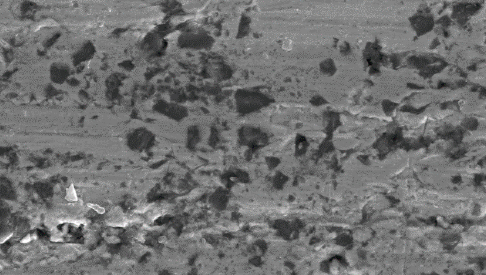
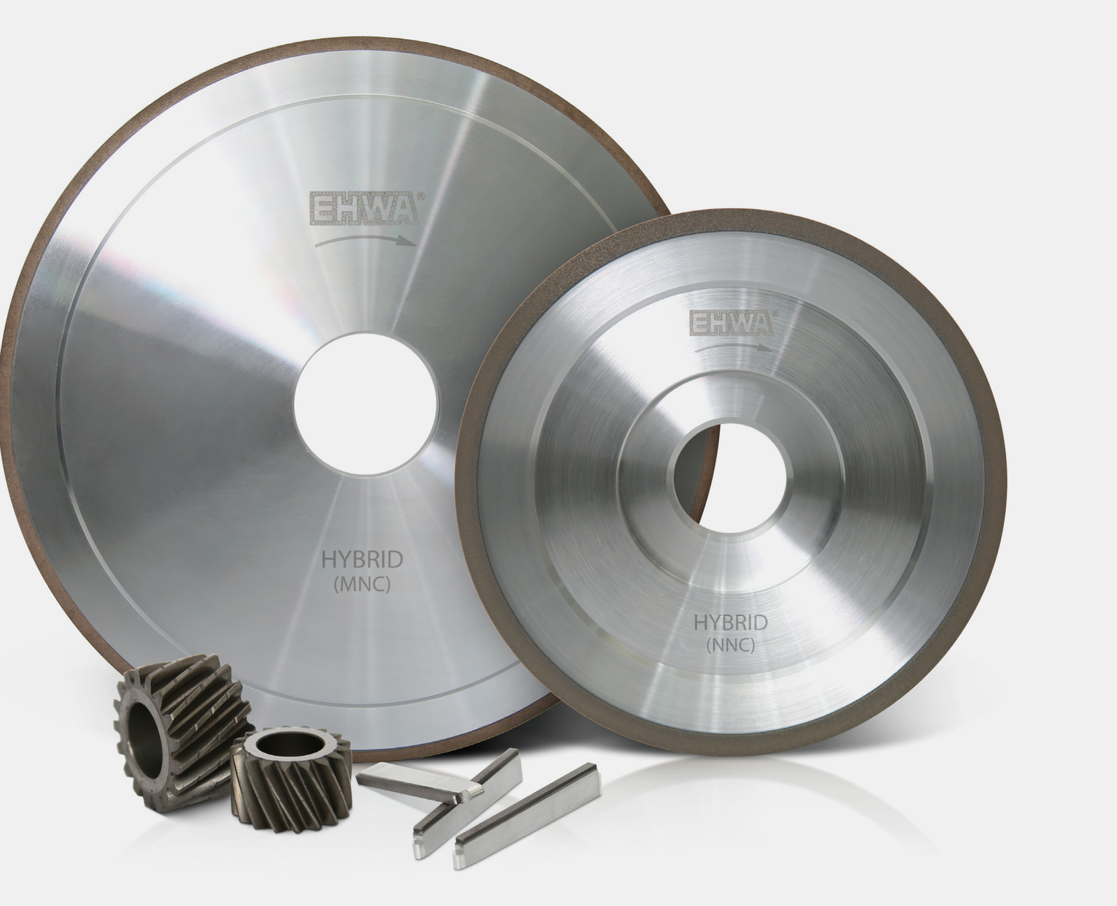
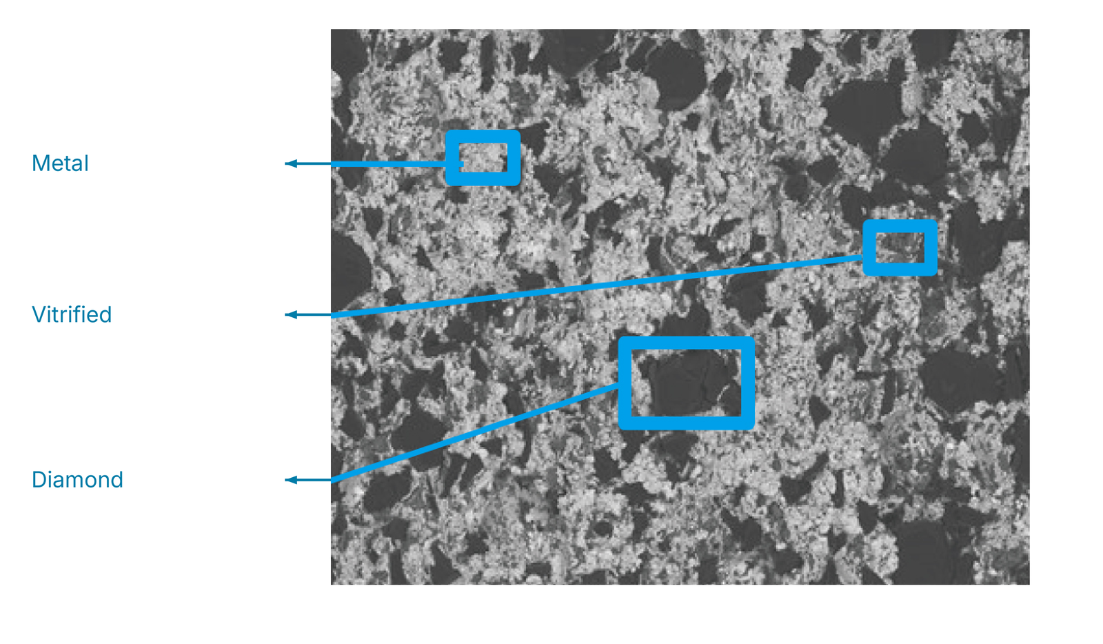
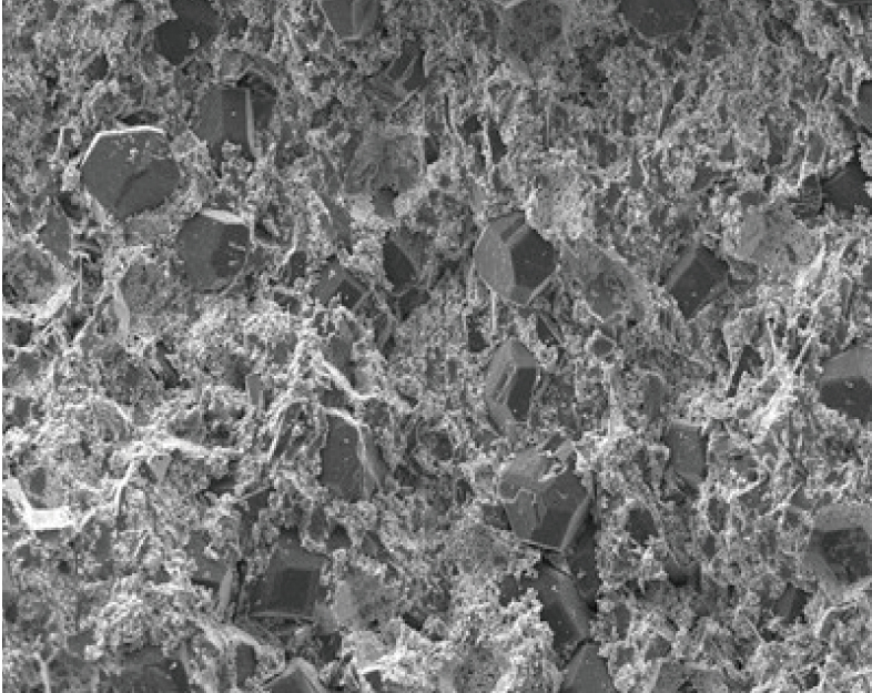
The metal/vitrified hybrid grinding wheel combines the wear resistance of metal bond with the grinding performance of vitrified bond. Long tool life and good profile stability are the central benefits. The micrographs identify metal, vitrified phase and diamond at the original marked locations, together with a further unlabelled view.
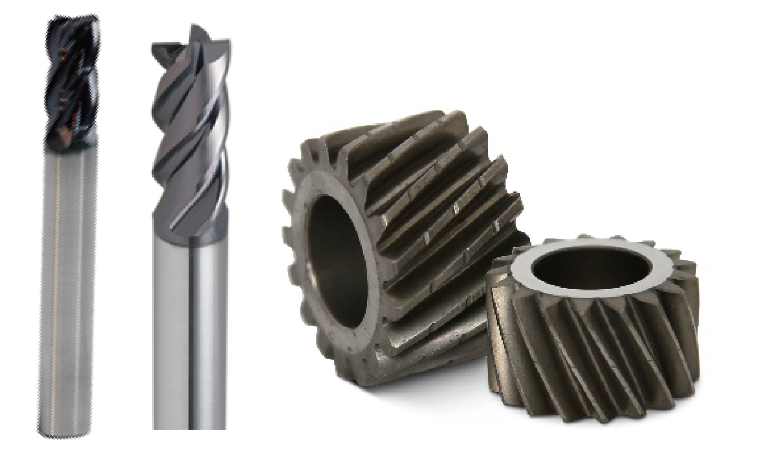
The document associates the range with the MEViOUS brand. Applications include tungsten carbide end mills and drills, other alloy tools and gear honing stones.
| Range feature | Source specification |
|---|---|
| Grit size | #60–#3000 |
| Wheel size | 40D–450D |
| MNC bond | MJ, MS Series |
The D designation is retained as printed; this table does not state an expanded unit.
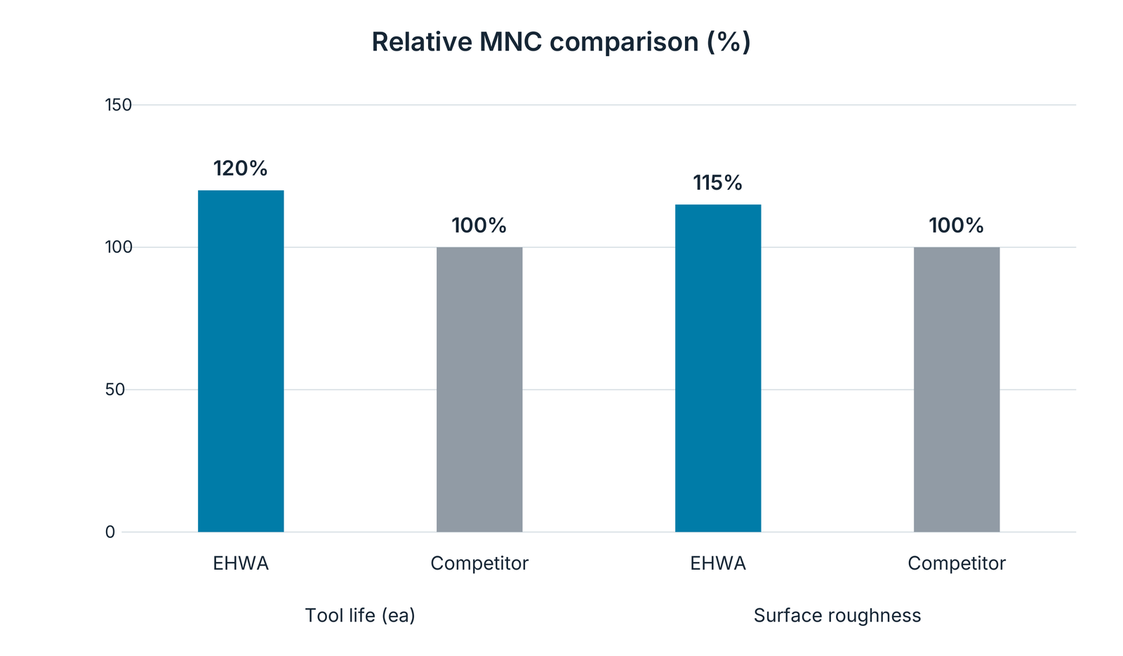
Complete relative performance comparison in this document
| Comparison feature | EHWA | Competitor |
|---|---|---|
| Tool life, source designation “Tool life (ea)” | 120% | 100% |
| Surface roughness, source designation “Surface roughness” | 115% | 100% |
The source presents both features as relative comparisons. For roughness it provides neither absolute Ra/Rz values nor a definition of the comparison index; 115% is therefore not converted into a general roughness improvement. This test remains separate from other MEViOUS trials.
Coordinate the right manufacturing process
For a tool recommendation, useful information includes the component drawing and material, grinding surface, machine and mounting, stock removal, target geometry and surface finish, and dressing and coolant conditions. Raceway profiles particularly require the dimensions and datum system; micro tools place cutting edge geometry and thermal loading at the centre of selection.
EHWA Europe supports the selection of grinding tools, superfinishing stones and dressers. Send your application to info@ehwadia.de or contact the team on +49 6173 99778-0.
Sources and technical scope
The complete content is based on the EHWA documents Bearing, pp. 1–10 (printed pp. 26–35), and 2.Tooling-Bearing-Glass, pp. 1–8. Shared CBN, rotary dresser and cup dresser content is consolidated; different applications, technical drawings, images and tests remain included. The publication years of these two source documents are not explicitly printed.
Additional technical context: EHWA Grinding Catalogue ENG 2022, p. 44 on cycle time with porous hybrid bond and TYROLIT: Your partner for tool grinding, p. 107 on dressing speed ratio. EHWA process values remain those of the two bearing documents.