Drilling, milling and turning for aluminium components, CV joints and housings
Design the tool around the component
The EHWA range combines solid-carbide drills with PCD and PCBN tools for producing drivetrain components. It covers aluminium alloys, steel CV-joint components, transmission and differential gears, scroll compressors, battery housings and motor housings. Tool body, cutting material and workpiece material are selected to suit each process.
| Application | Tool range |
|---|---|
| Aluminium alloys | Solid-carbide drills, XF face milling cutters and other face milling cutters |
| Steel drilling | ET220 solid-carbide drills with coating variants |
| CV joints | EBC52X PCBN turning grade; PCBN end mills with four or six flutes |
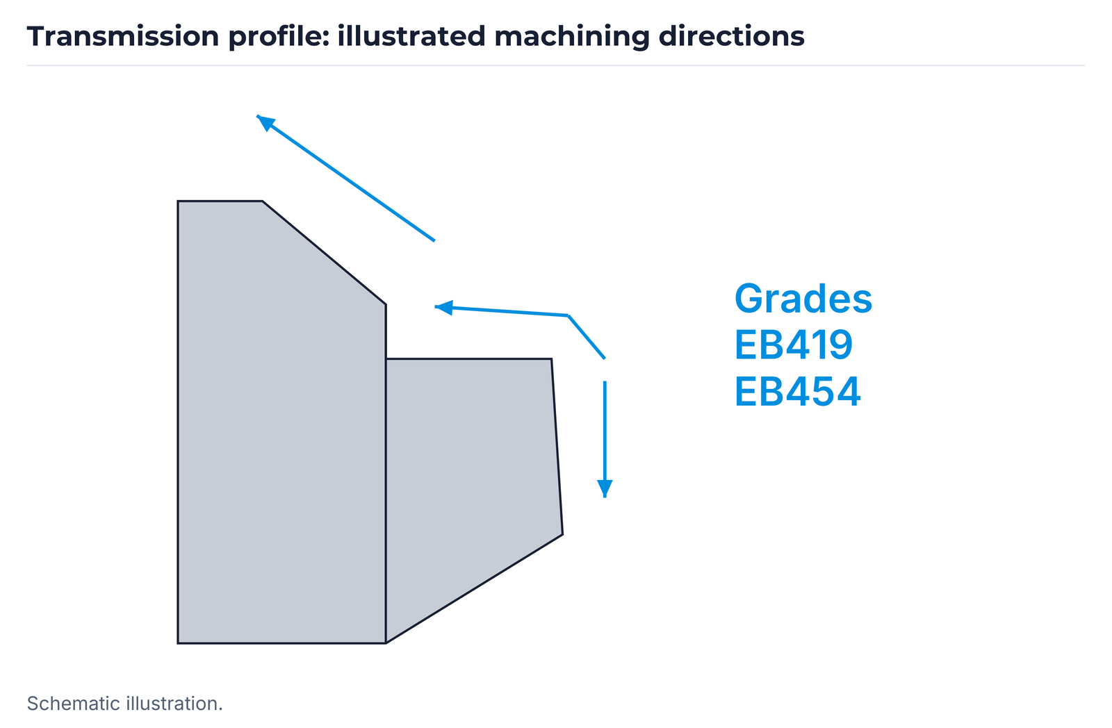
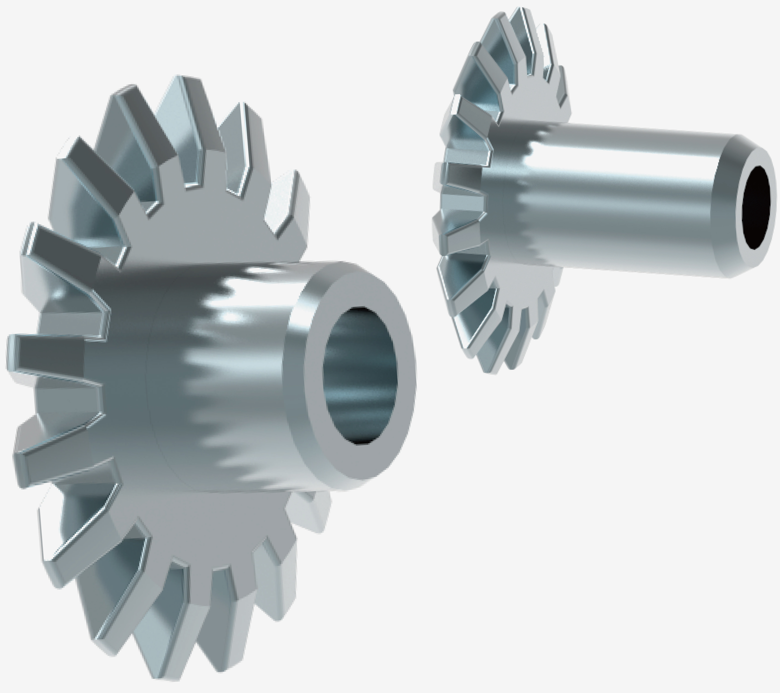
| Transmission and differential gears | Turning tools in grades EB419 and EB454 |
| Aluminium scroll compressors | Customised PCD end mills |
| Aluminium battery housings | PCD end mills with a helical cutting-edge arrangement |
| Motor housings | Special boring tool with an aluminium/CFRP body concept |
Solid-carbide drills for aluminium alloys
The aluminium drills belong to the ETDB family. The range contains the following six complete item-code and dimensional combinations:
| Item code | D1 | D2 | L | FL | OAL |
|---|---|---|---|---|---|
| ETDB 43 60 025 080 2N | 4.3 | 6.0 | 25 | 40 | 80 |
| ETDB 51 80 025 080 2N | 5.1 | 8.0 | 25 | 40 | 80 |
| ETDB 69 100 030 100 2N | 6.9 | 10.0 | 30 | 50 | 100 |
| ETDB 86 120 035 105 2N | 8.6 | 12.0 | 35 | 55 | 105 |
| ETDB 104 140 040 110 2N | 10.4 | 14.0 | 40 | 60 | 110 |
| ETDB 140 160 040 110 2N | 14.0 | 16.0 | 40 | 60 | 110 |
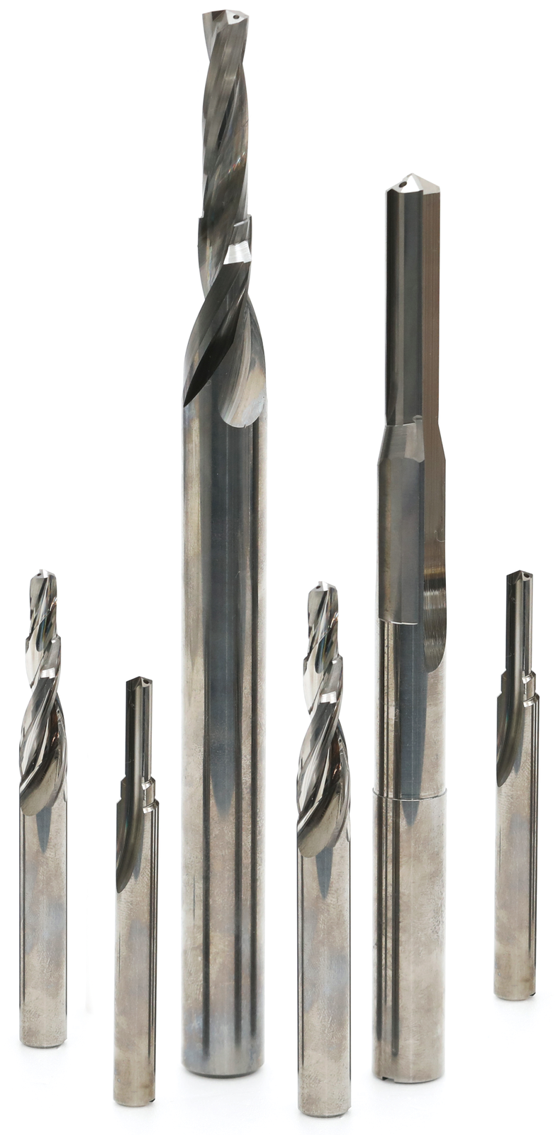
ET220 solid-carbide drills for steel
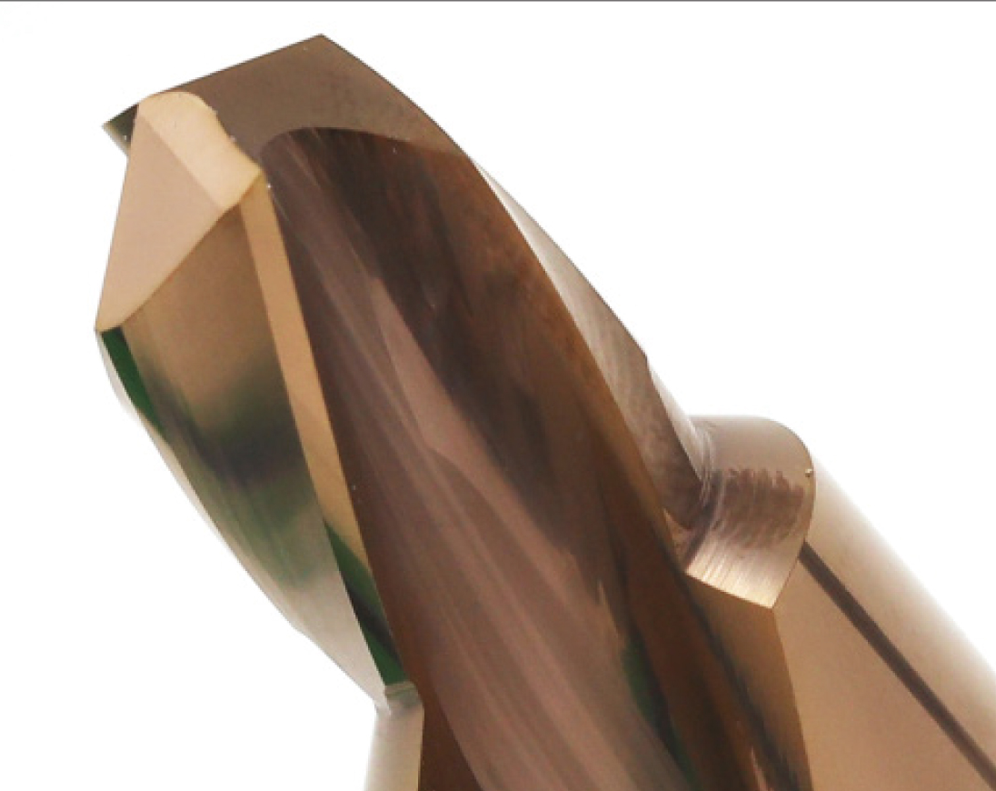
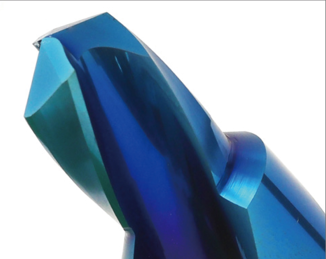
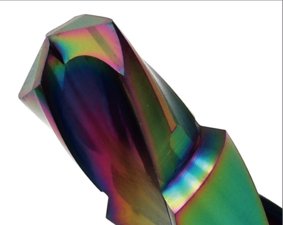
ET220 is described as an ultra-fine carbide with high hardness and fracture toughness. For steel, EHWA specifies helical drills with two to three coolant holes. The coating overview distinguishes TA as the conventional design and H1, H2 and H3 as coating variants for interrupted cutting.
| Coating designation | Range classification |
|---|---|
| TA | Conventional coating |
| H1 | Coating for interrupted cutting |
| H2 | Coating for interrupted cutting |
| H3 | Coating for interrupted cutting |

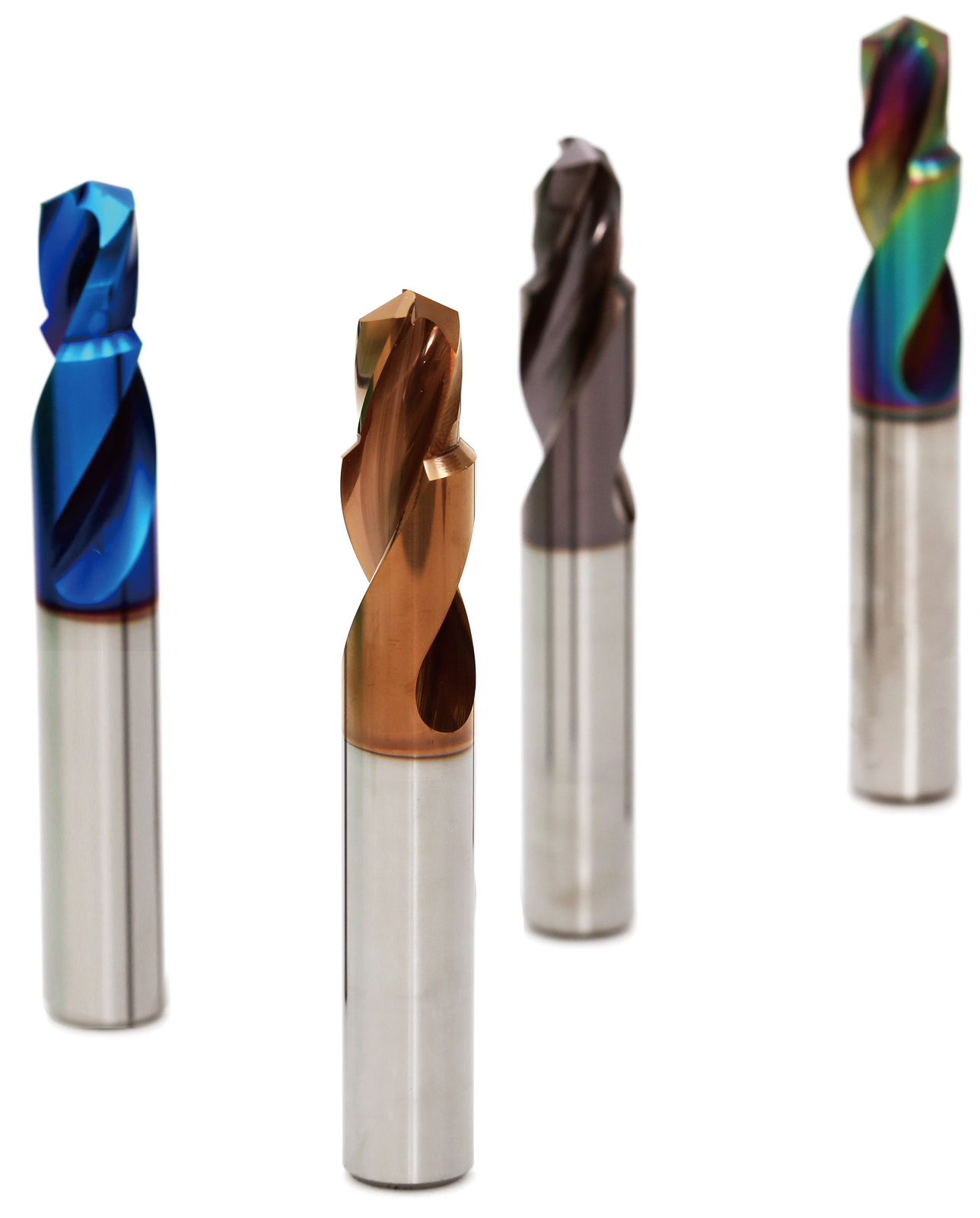
| Item code | D1 | D2 | L | FL | OAL |
|---|---|---|---|---|---|
| ETDH 43 60 025 080 2N | 4.3 | 6.0 | 25 | 40 | 80 |
| ETDH 51 80 025 080 2N | 5.1 | 8.0 | 25 | 40 | 80 |
| ETDH 69 100 030 100 2N | 6.9 | 10.0 | 30 | 50 | 100 |
| ETDH 86 120 035 105 2N | 8.6 | 12.0 | 35 | 55 | 105 |
| ETDH 104 140 040 110 2N | 10.4 | 14.0 | 40 | 60 | 110 |
| ETDH 140 160 040 110 2N | 14.0 | 16.0 | 40 | 60 | 110 |
Drill codes and dimensional drawings
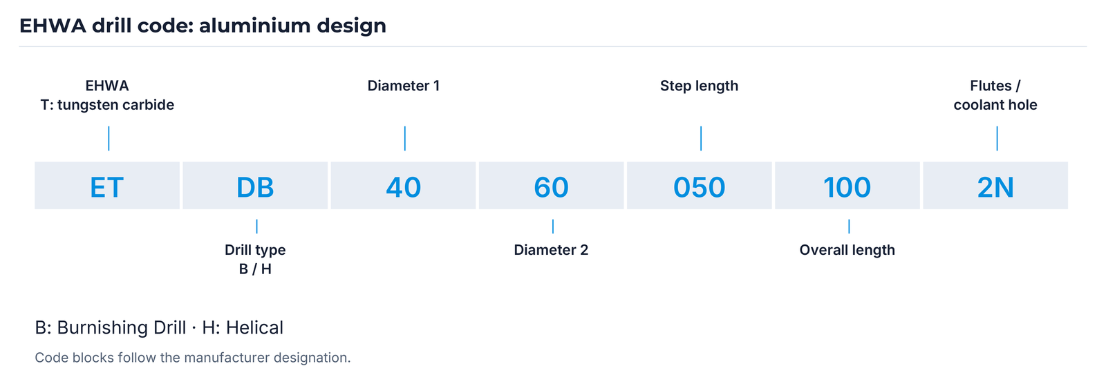
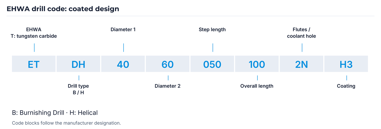
The codes are explained using the illustrated examples ET DB 40 60 050 100 2N and ET DH 40 60 050 100 2N H3. The number blocks remain manufacturer designations; the associated dimensions are taken from the item table and tool drawing.
| Code element | Meaning |
|---|---|
| ET | EHWA; T denotes tungsten carbide |
| DB / DH | Drill type: B = Burnishing Drill; H = Helical |
| 40 | Diameter 1 |
| 60 | Diameter 2 |
| 050 | Step length |
| 100 | Overall length |
| 2N | Designation block for flute count / coolant hole |
| H3 | Coating designation in the coated example |
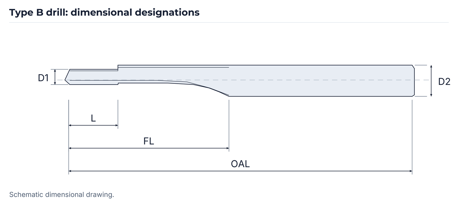
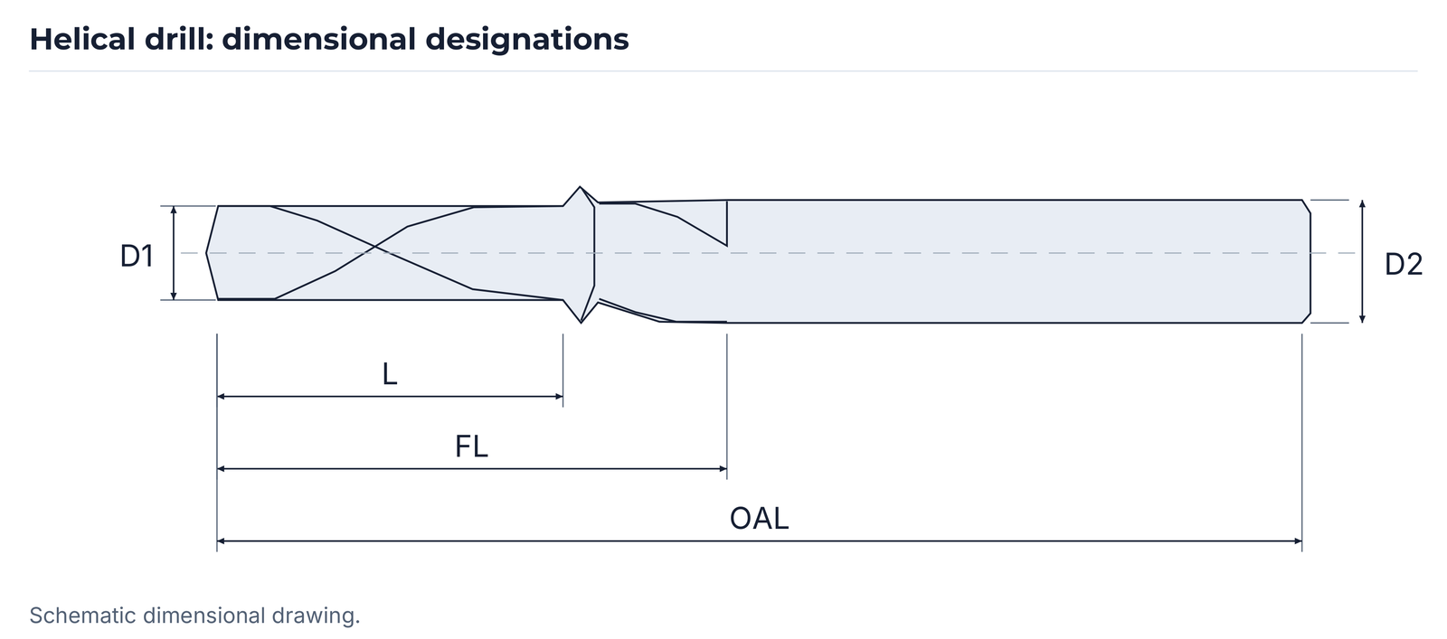
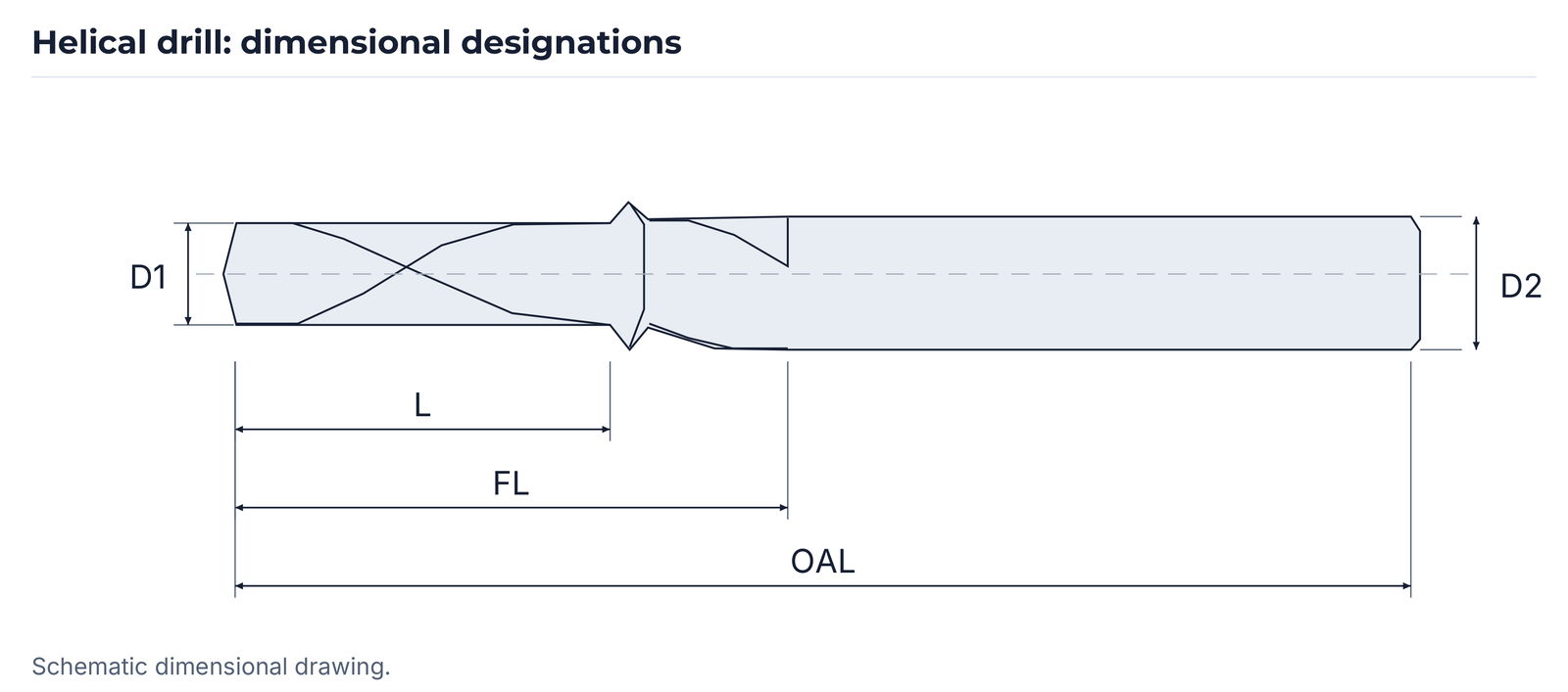
D1 and D2 denote the two diameters; L, FL and OAL remain the drawings' length designations. The dimensional tables do not state an explicit unit. The binding dimensional definitions and units are agreed using the tool drawing.
EBC52X: PCBN turning for CV joints
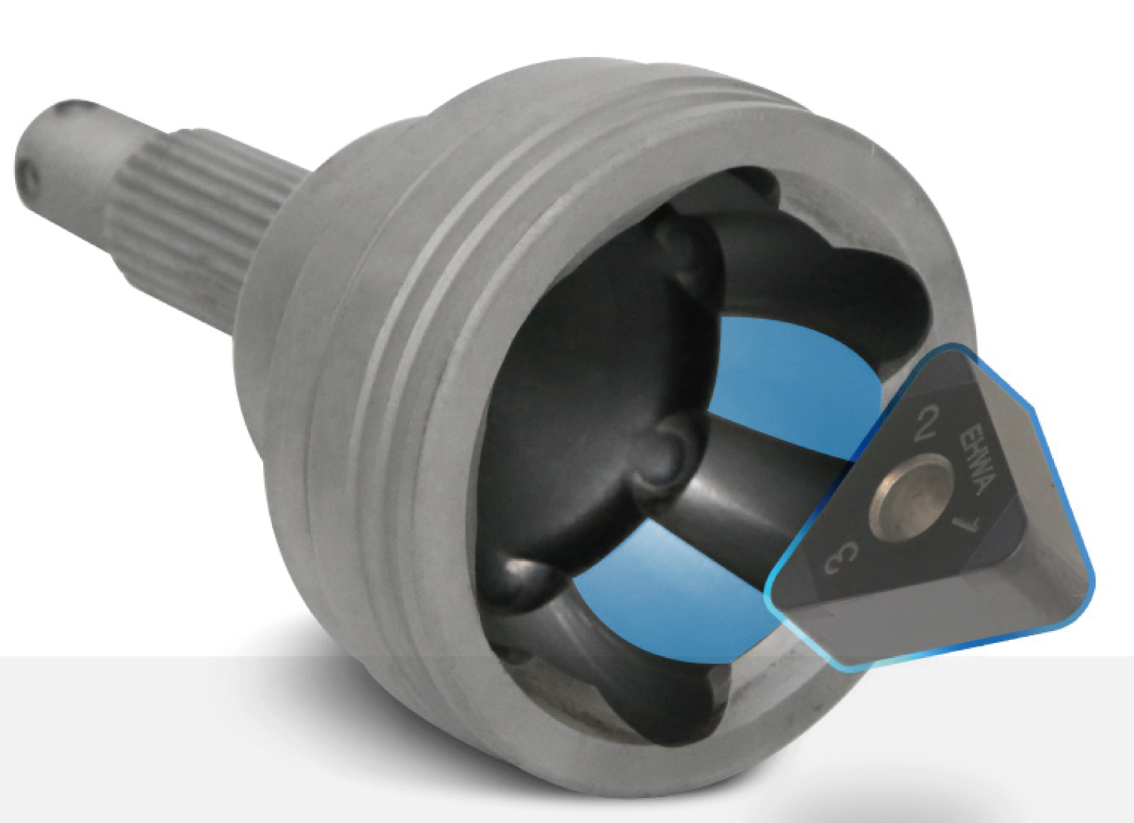
EBC52X is a high-CBN-content PCBN grade for continuous and interrupted machining of heat-treated steel CV-joint components. EHWA describes the grade as capable under demanding machining conditions. The two examples show different cutting data for outer and inner components.

| Trial specification | Outer Race Turning | Inner Race Turning |
|---|---|---|
| Workpiece | Forged steel | Forged steel |
| Cutting speed | 120 m/min | 200 m/min |
| Feed rate | 0.10–0.12 mm/rev | 0.20 mm/rev |
| Depth of cut ap | 0.10–0.20 mm | 0.09–0.15 mm |
| Coolant | Dry machining | Dry machining |
| Cutting mode | Interrupted cutting | Interrupted cutting |
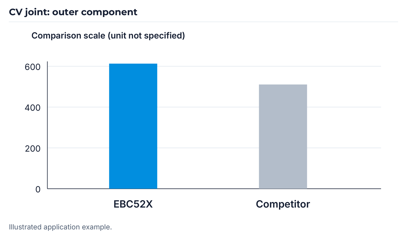
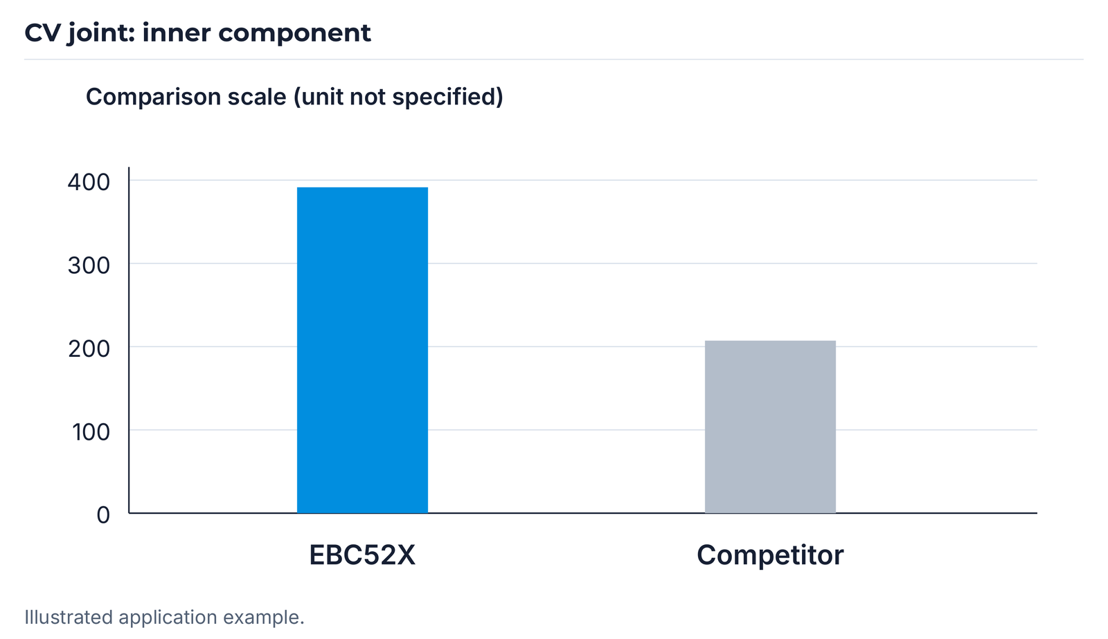
The bars compare EBC52X with a competitor's tool under the stated conditions. The diagrams do not identify the unit of their comparison scale; neither part count nor machining time is derived as an additional value.
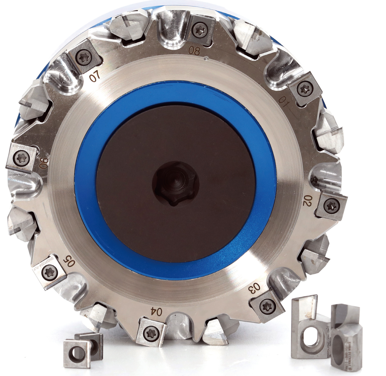
XF face milling cutters for aluminium alloys
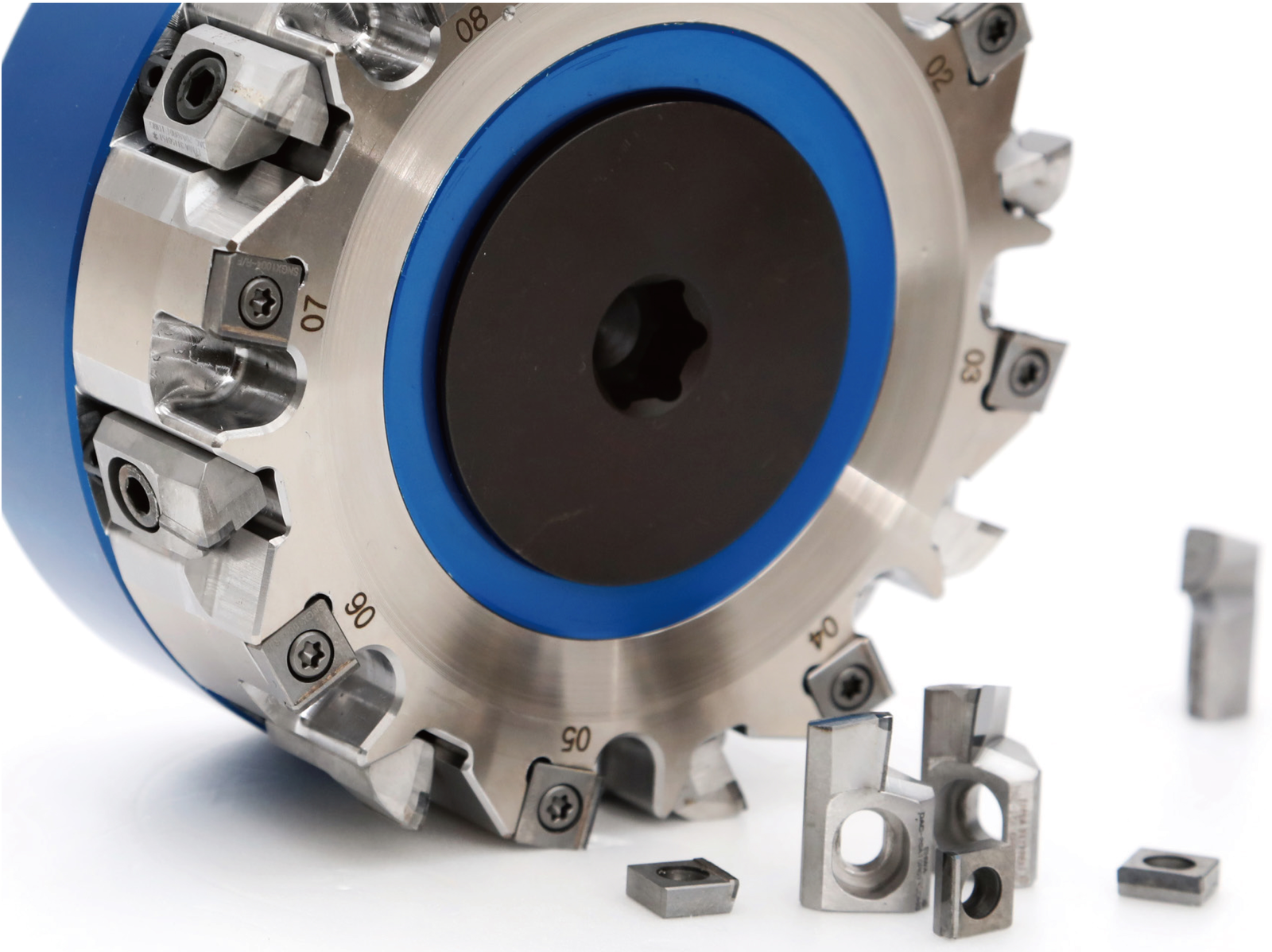
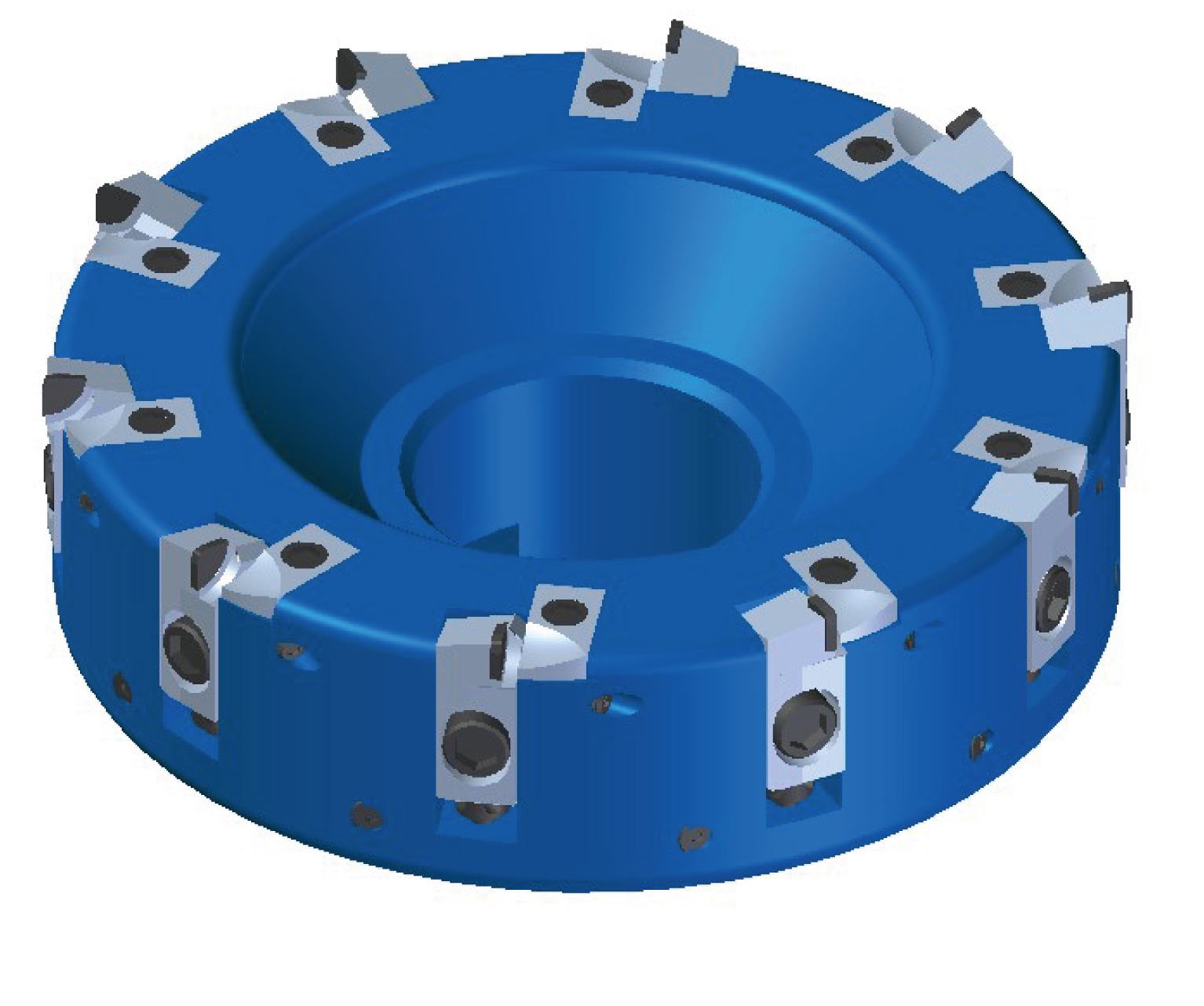
XF face milling cutters are offered for roughing and finishing. The range combines cutter bodies, inserts, cartridges and arbors; dimensions can be customised.
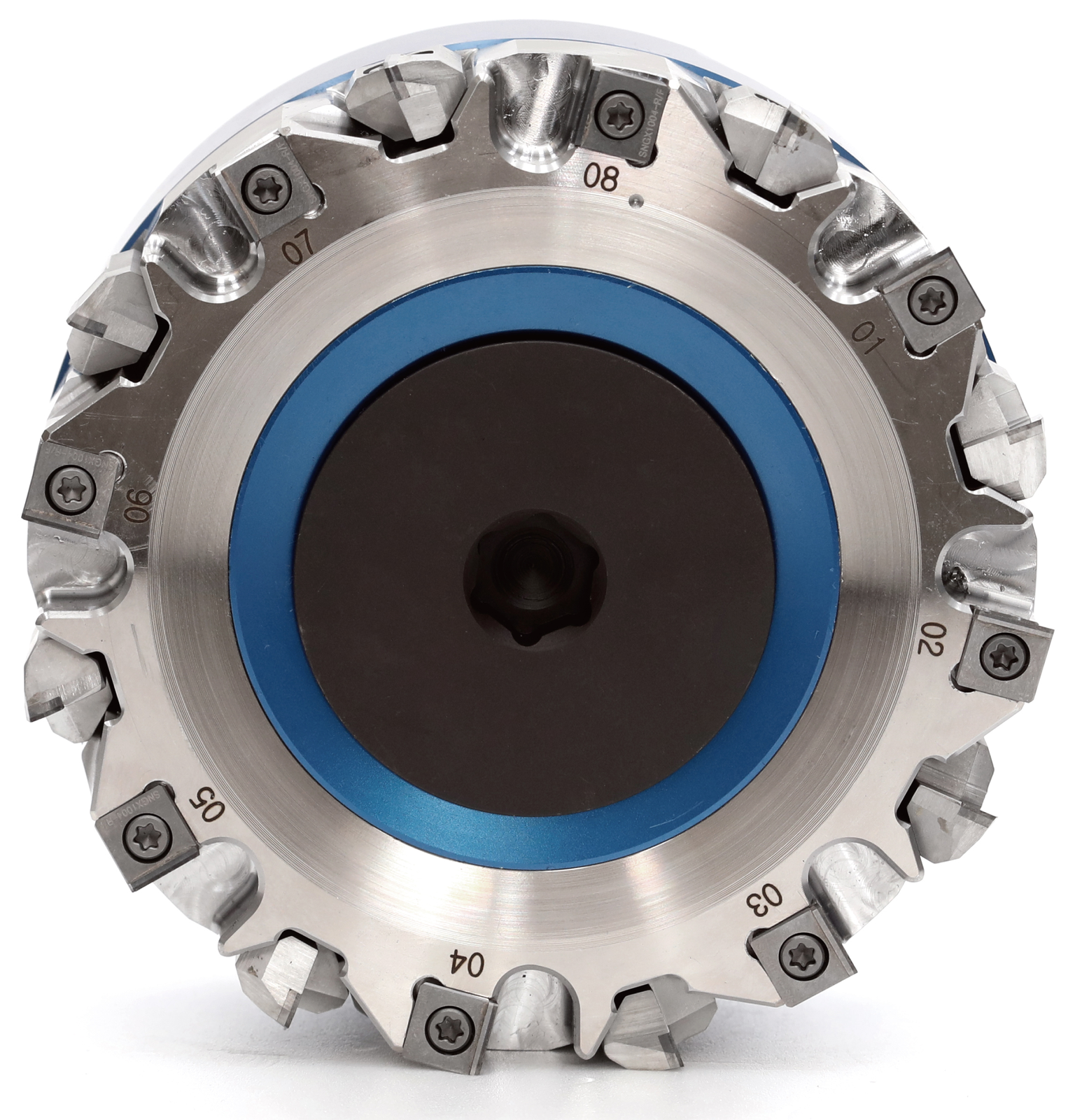
Dimensions and tooth count
| Type | ØD | Ød | A | B | H | Teeth |
|---|---|---|---|---|---|---|
| XF 10050 -16R (L) | 100 | 31.75 | 12.7 | 8 | 50 | 16 |
| XF 12563 -16R (L) | 125 | 38.1 | 15.9 | 10 | 63 | 16 |
| XF 16063 -16R (L) | 160 | 50.8 | 19.0 | 11 | 63 | 16 |
| XF 20063 -18R (L) | 20 | 47.625 | 25.4 | 14 | 63 | 18 |
| XF 25063 -18R (L) | 250 | 47.625 | 25.4 | 14 | 63 | 18 |
For type XF 20063 -18R (L), the item table gives ØD as 20, while the separate cutting-data table contains ØD 200. The additional EHWA XF data sheet checked contains the same discrepancy; the diameter is confirmed before tool design.
For all five types, the table specifies the XF10 - SN insert and XF CF / XF SD cartridge designs.
| Type | Arbor |
|---|---|
| XF 10050 -16R (L) | FMA 31.75 |
| XF 12563 -16R (L) | FMA 38.1 |
| XF 16063 -16R (L) | FMA 50.8 |
| XF 20063 -18R (L) | FMA 47.625 |
| XF 25063 -18R (L) | FMA 47.625 |
Stated maximum cutting conditions
| ØD | Maximum speed (min⁻¹) | Depth of cut ap (mm) |
|---|---|---|
| 100 | 11 000 | 3 |
| 125 | 9 000 | 3 |
| 160 | 7 000 | 3 |
| 200 | 5 500 | 3 |
These cutting data belong to the tool designs shown. The sheet does not specify an additional maximum speed for ØD 250.
PCBN end mills for CV joints
EHWA develops precise PCBN end mills as a cutting solution for suitable CV-joint processes. The range includes four- and six-flute designs. The six-flute design is intended for high durability in high-speed machining. Customised designs and tooling solutions complement its cutting performance.
| Feature | Design |
|---|---|
| Body type | HFS12 |
| Cutting material | PCBN |
| Flutes | 4 F and 6 F |
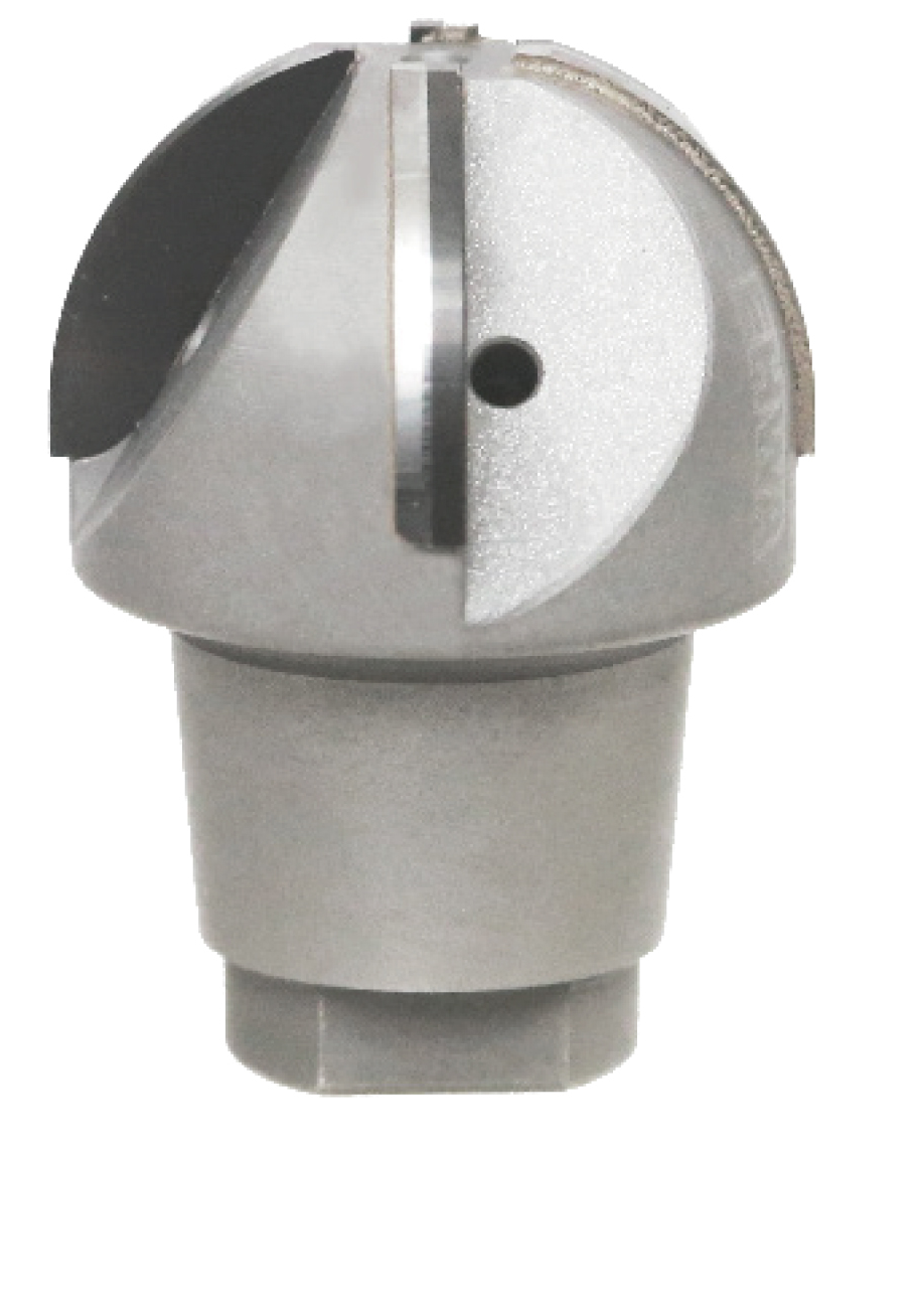
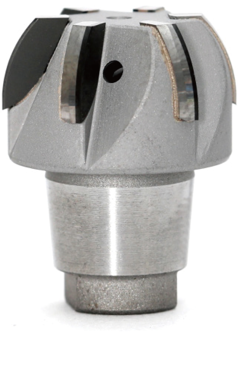
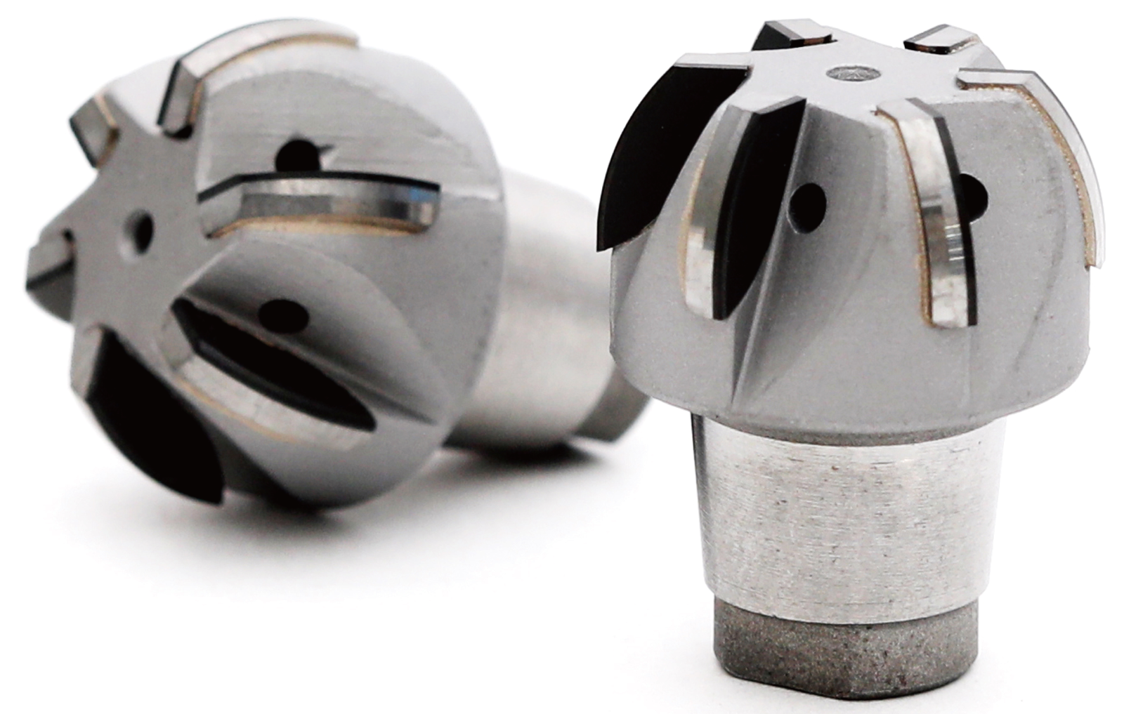
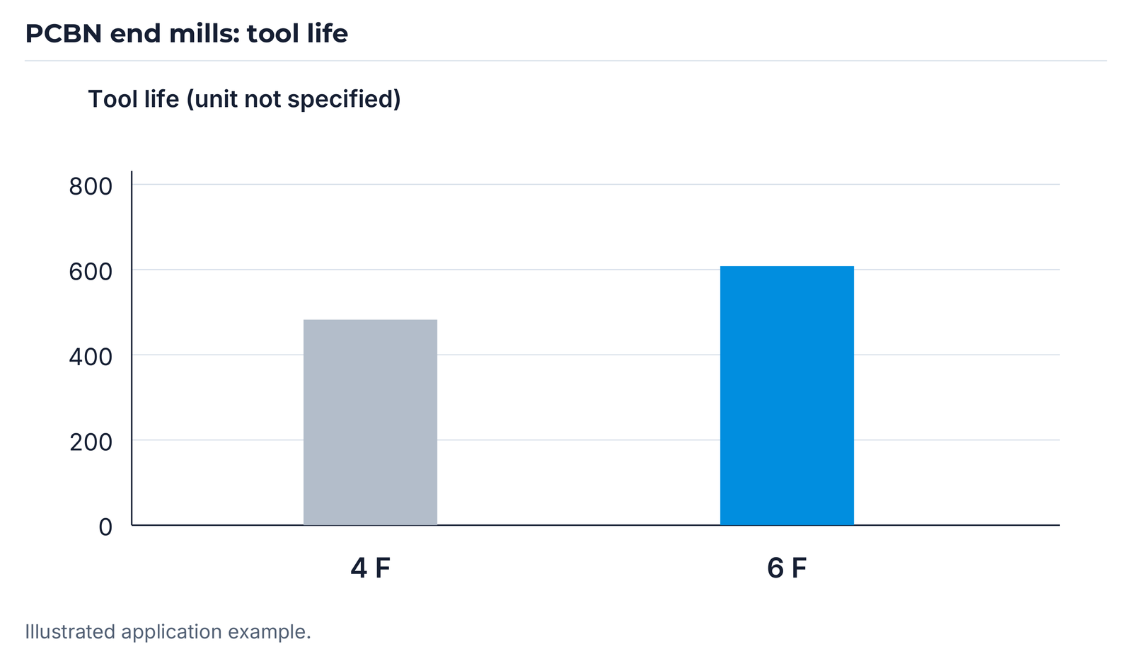
The chart shows higher tool life for the six-flute design in the illustrated comparison. The scale is labelled TOOL LIFE but does not state a unit; no additional trial conditions are added here.

Turning for transmission and differential gears
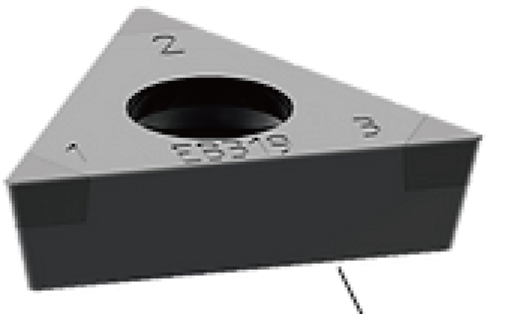
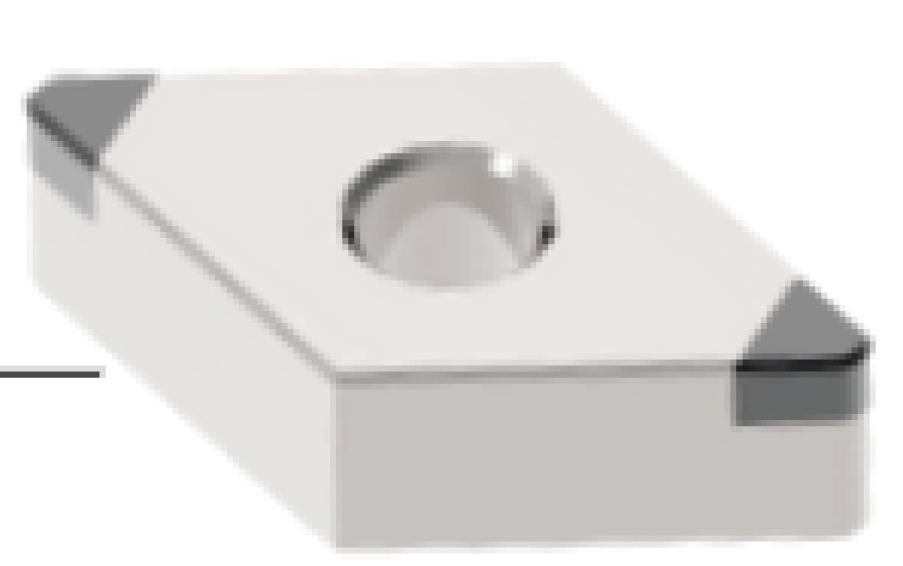
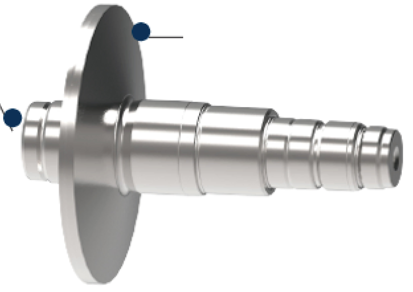
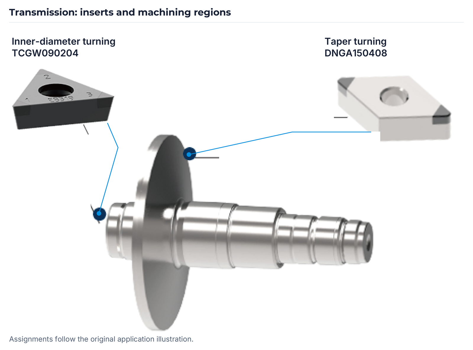
For the illustrated internal and taper turning, EHWA specifies grades EB419 and EB454. The insert designations are assigned to the two applications shown:
| Application | Insert designation |
|---|---|
| Inner-diameter turning | TCGW090204 |
| Taper turning | DNGA150408 |
| Trial specification | Value |
|---|---|
| Workpiece | SCM418H |
| Cutting speed | 80–120 m/min |
| Feed rate | 0.07–0.10 mm/rev |
| Depth of cut ap | 0.05–0.06 mm |
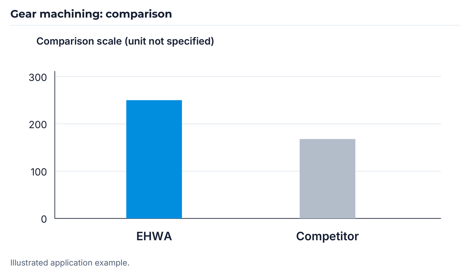
The complete comparison scale is retained. It does not name a unit or measured quantity; the bar-chart advantage is therefore presented as the application result shown.
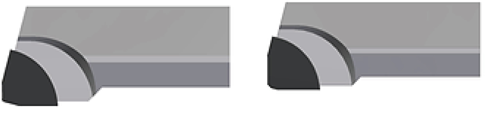
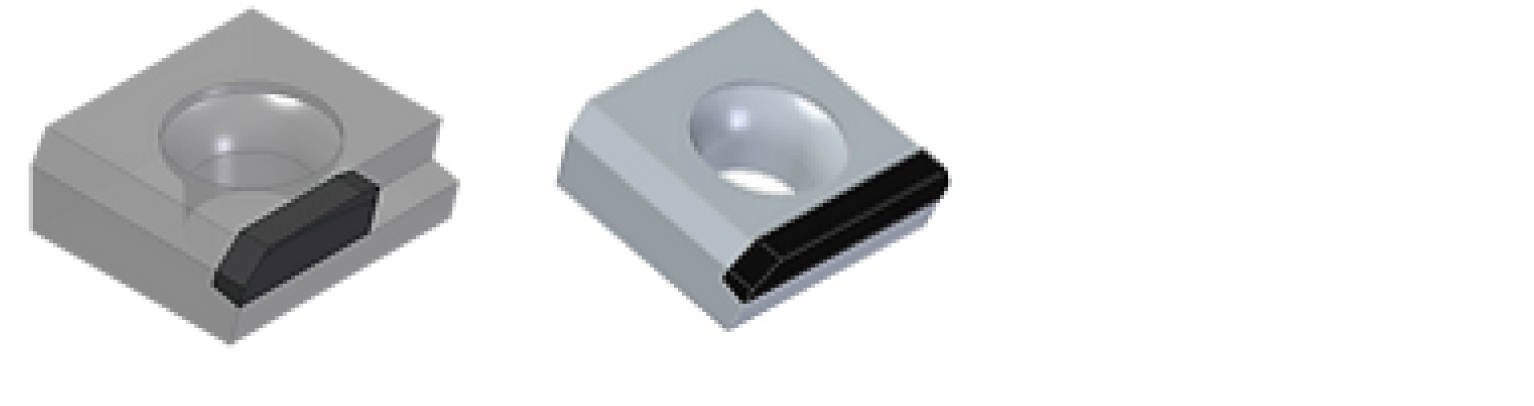
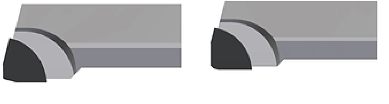
AF, BF, CF and XF face milling families
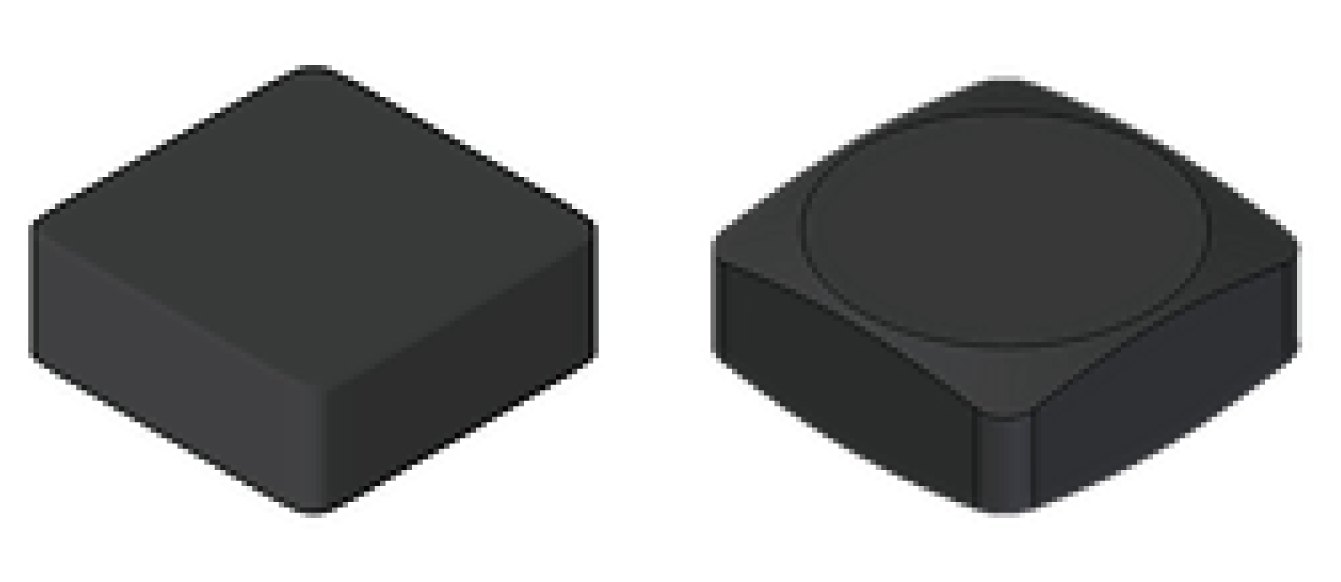
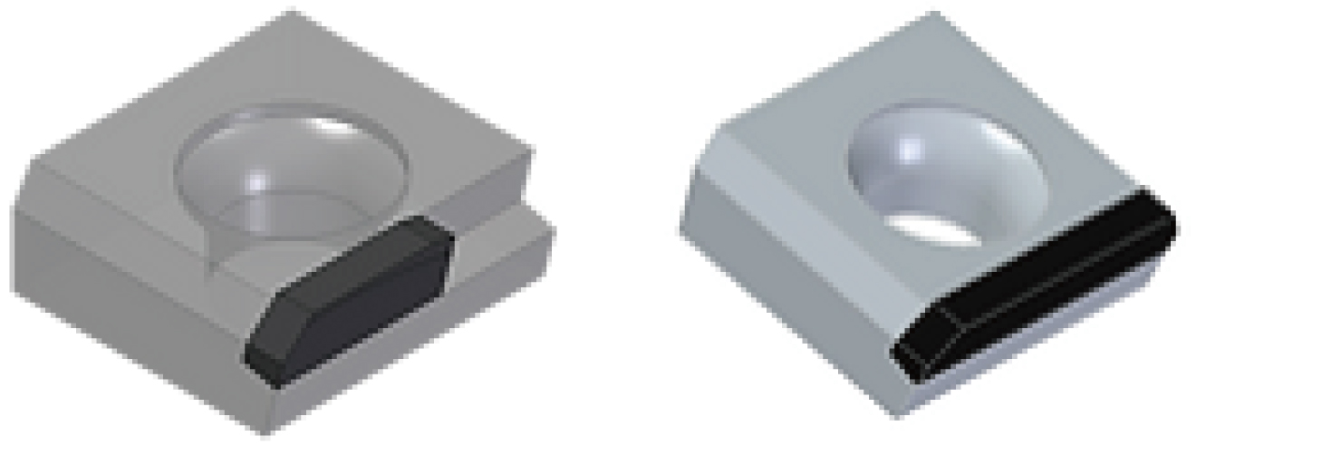
The face milling families have different priorities in surface quality, tool life, burr-free machining and universal design. XF complements the range for roughing and finishing.
| Family | Size designation | Design and associated inserts |
|---|---|---|
| AF | 80D–250D | Surface quality and tool life; SNGN 1204, SNGX 1204 |
| BF | 125D–250D | Designed for burr-free machining and long tool life; SNGX 1004-R, SNGX 1004-F |
| CF | 50D–250D | Universal EHWA design; CFR, CFW |
| XF | See the XF range table | Roughing and finishing; SNGX 1004-R, SNGX 1004-F and CFR, CFW |


PCD end mills for aluminium scroll compressors
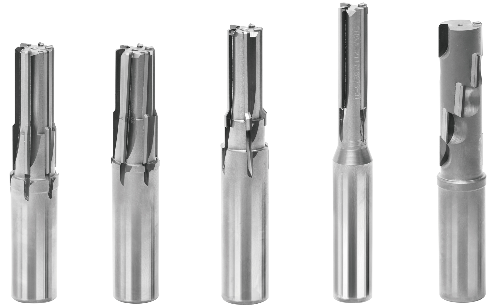
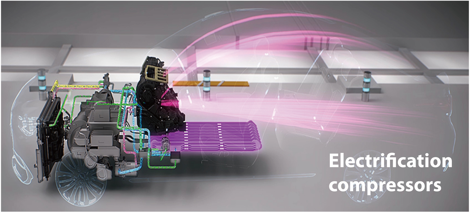
EHWA offers customer-optimised PCD end mills for scroll compressors. Precise machining supports production efficiency and compressor-component quality. The illustrated designs show different cutting-edge and step geometries for this aluminium application.
PCD end mills for aluminium battery housings
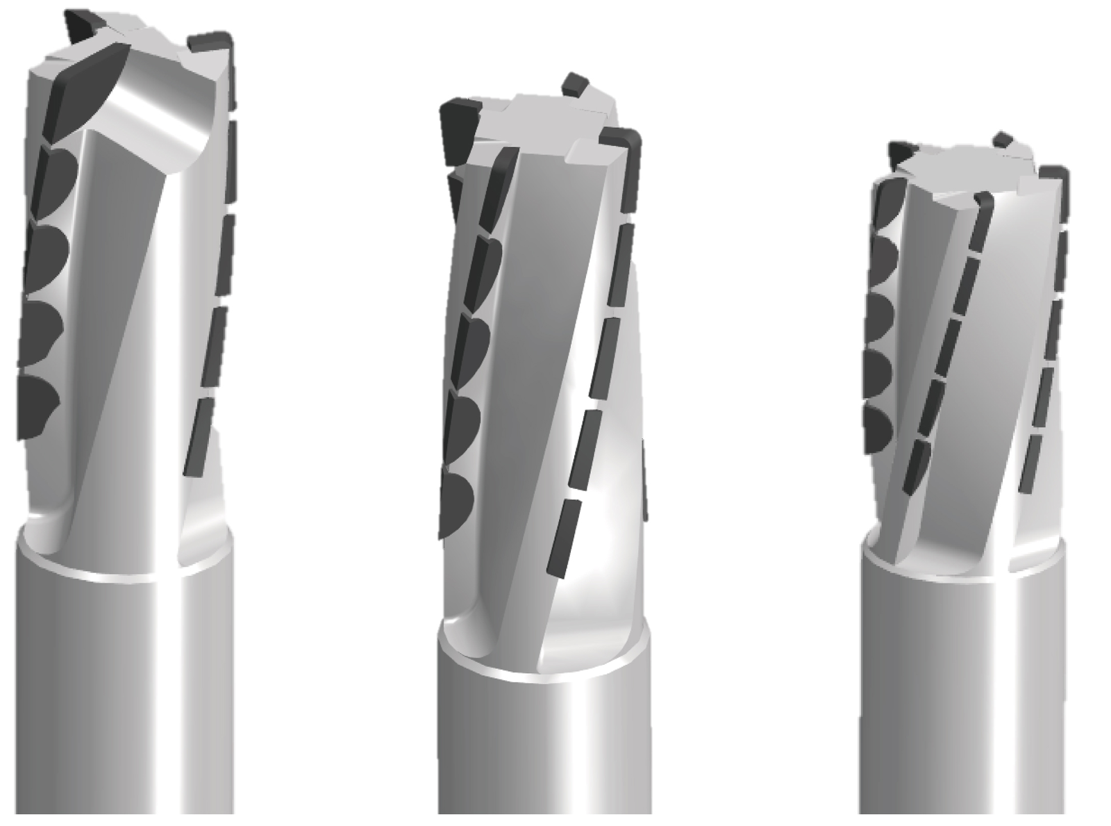
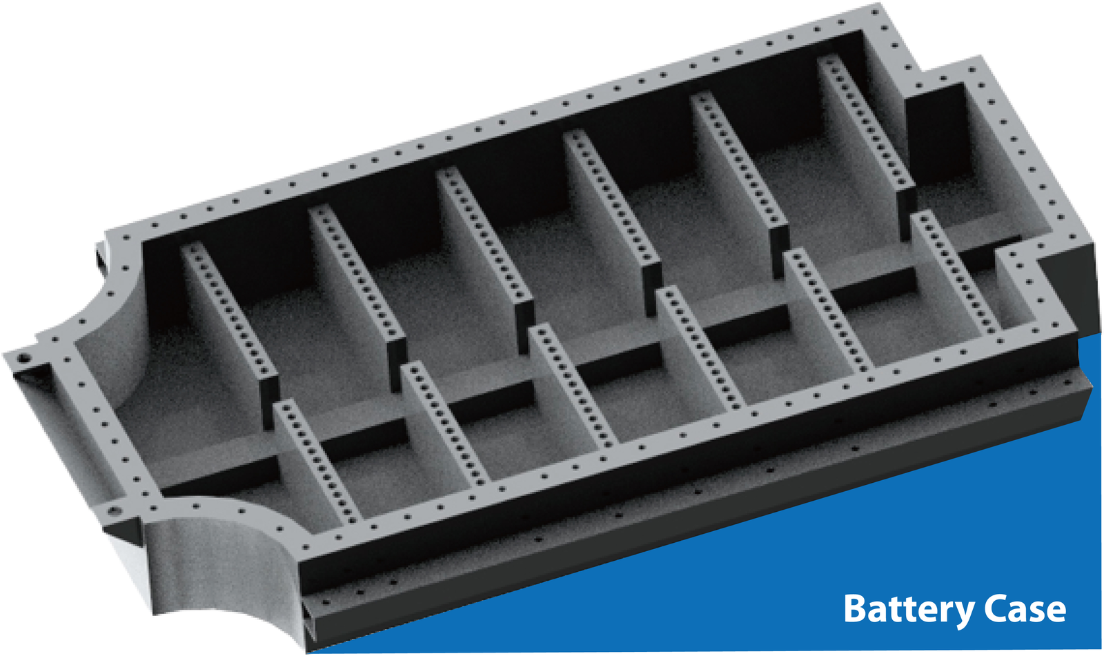
The helical cutting-edge arrangement of the PCD end mills is designed for high material removal rates. EHWA specifies burr-free machining through a high rake angle, high machining speed and efficiency, and improved surface roughness as the aims of this design.
Special boring tool for motor housings
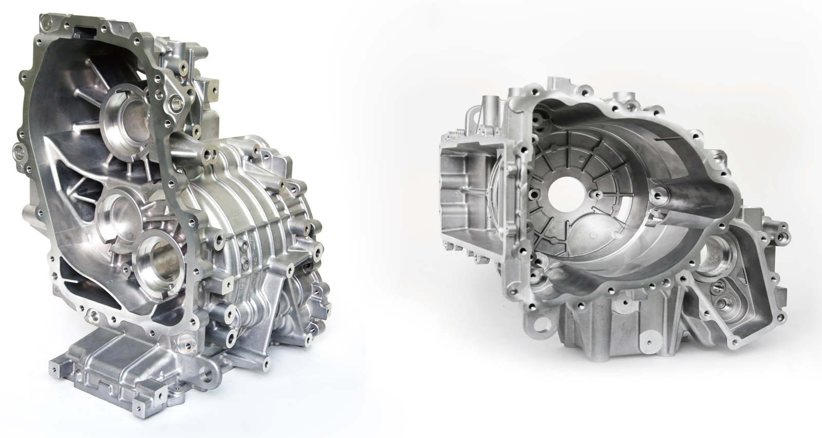
Electric motors are designed for high power, efficiency and capacity with low weight. For machining their housings, EHWA describes a tooling concept combining aluminium and carbon-fibre-reinforced polymer (CFRP). The material combination concerns the tool body and is intended to improve vibration damping.
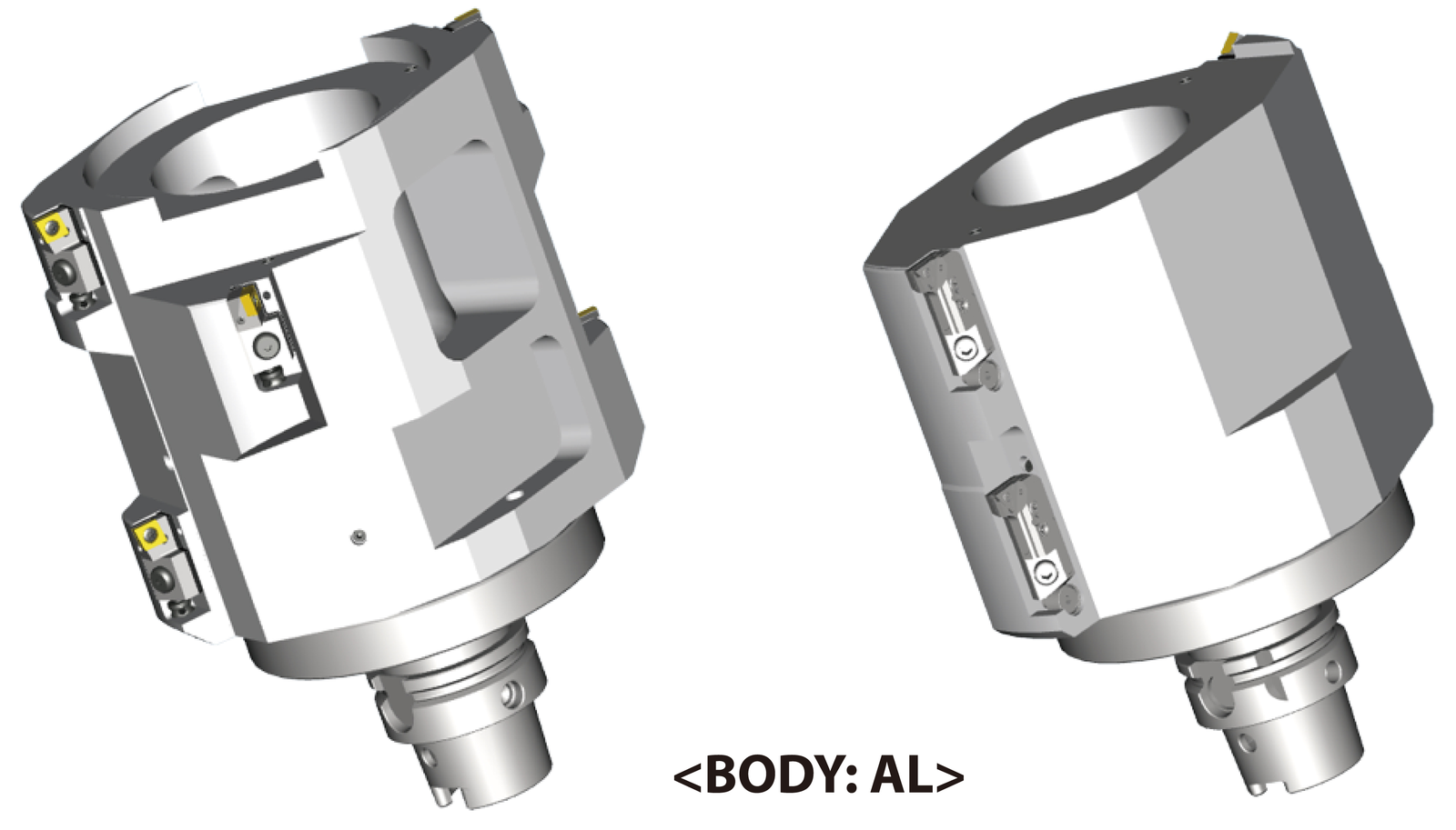
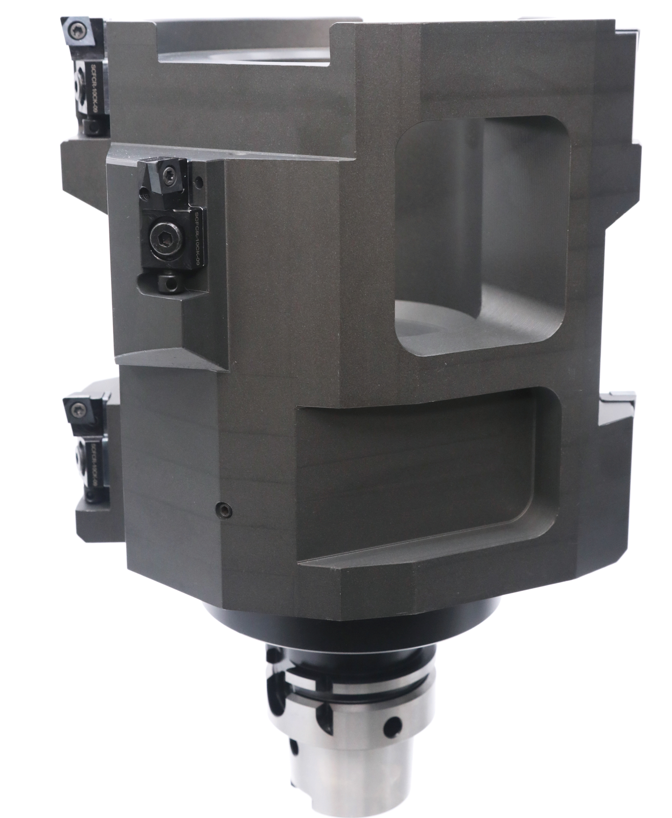
The section drawing shows the machining arrangement with housing, tool body and mounting interface. All stated dimensions and cutting-edge-count designations are retained:
| Drawing specification | Value |
|---|---|
| Diameter with tolerance | Ø201.7 ±0.05; Z = 2 |
| Additional diameter with tolerance | Ø199.5 ±0.1; Z = 2 |
| Interface diameter | Ø140 |
| Axial dimensions | 60; 140; 70; 210 |

The drawing describes the example design shown. Dimensional definitions and units are established for the particular motor housing using the agreed tool drawing.
Stripping blades for hairpin motor windings
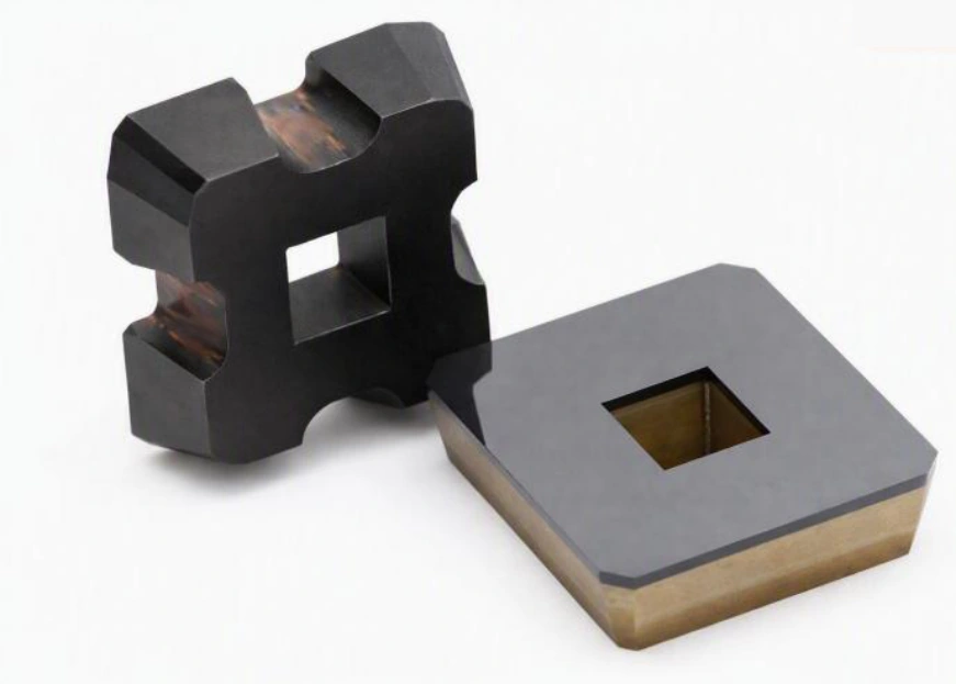
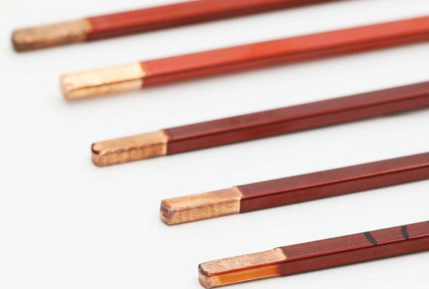
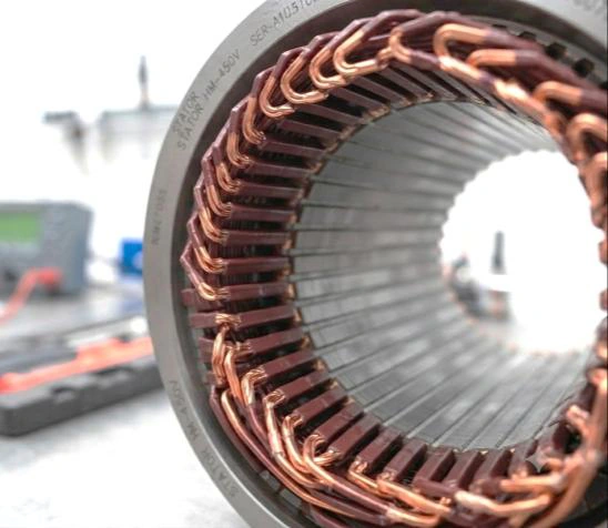
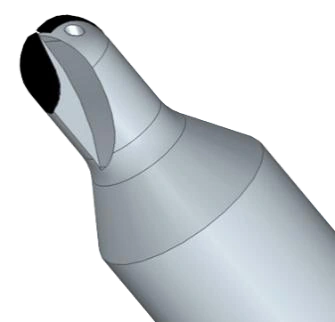
Rectangular copper conductors with defined corner radii place specific demands on insulation stripping. EHWA develops precision blades made from superhard cutting materials with a contour matched to the conductor profile. They are intended to remove PEEK and PAI insulation from hairpin conductors.
The design aims to produce a clean copper surface while minimising damage to the conductor. This supports preparation of the electrical connection and subsequent laser welding. Tool contour, conductor dimensions, insulation and the NC machining sequence are specified together. The source describes long tool life and consistent machining accuracy as development objectives; the actual result is checked in the relevant process.
| Design feature | Application context |
|---|---|
| Conductor | Rectangular copper conductor / hairpin |
| Profile | Straight faces and their associated corner radii |
| Insulation | PEEK and PAI |
| Tool | Precision stripping blade with a matched contour |
| Subsequent step | Preparation of the electrical connection and laser welding |
PCBN grades for bearing components
The additional grade overview distinguishes EBC57S, EBC16S, EBC190 and EBC100X. The following grain sizes and applications refer to the 2026 Automotive source edition. Selection depends on bearing design, material, interrupted cutting and machining stage.
| Grade | Grain size [µm] | Listed applications | Described emphasis |
|---|---|---|---|
| EBC57S | 1–2 | Shaft bearings | Wear resistance; solid form |
| EBC16S | 1–4 | Shaft bearings, hub bearings, tapered roller bearings | Wear and chemical resistance; solid form |
| EBC190 | 2–4 | Shaft bearings, hub bearings, tapered roller bearings | Wear and friction resistance |
| EBC100X | 2–10 | Roller bearings, tapered roller bearings | Wear, friction and impact resistance; solid form |
The source also compares toughness, wear resistance and cost benefit qualitatively. These selection criteria are shown without a numerical test scale. The four micrographs show the respective grades at the source's stated magnification of 1,000×.
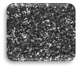
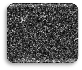
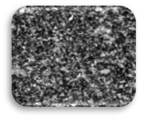
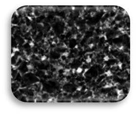
The original table labels its percentage row “Diamond vol (%)”, although the table concerns PCBN grades. The material attribution of that row is unresolved, so it is not used as a confirmed diamond or CBN volume content. All clearly identified grade, grain-size and application data are retained.
Inserts and machining locations on a bearing
The bearing illustration assigns three insert designations to specific machining areas: the outer race, inner race, hub shaft and inner diameter. The designation identifies the illustrated insert form; the grade and cutting-edge preparation are selected for the machining task.
| Machining area | Source insert designation |
|---|---|
| Outer race | VBGW160408 |
| Inner race | VBGW160408 |
| Hub shaft | DNGA150408 |
| Inner diameter | CCGW09T304 |
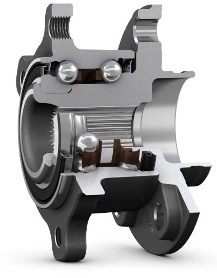
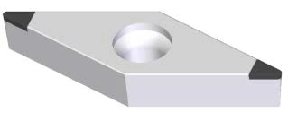
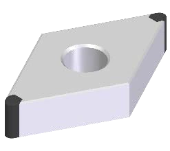
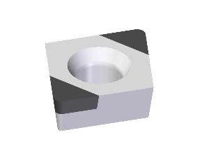
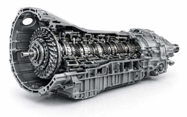
The additional component examples place the PCBN programme in hub-bearing and transmission-bearing applications. They illustrate the assembly context of the machined bearing parts.
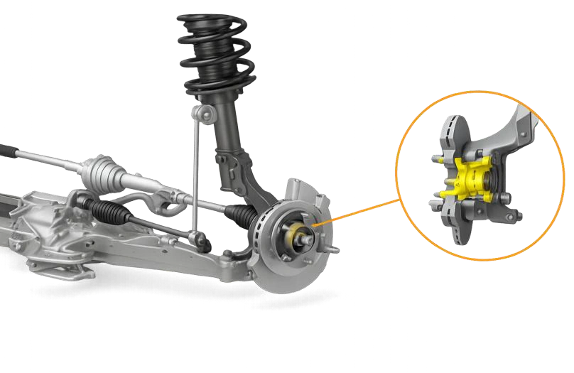
PCBN ball endmills for ball tracks
For hard milling of ball tracks, EHWA shows PCBN ball endmills in HFS and normal forms. The associated grade overview distinguishes EB510 and EB10X. The cutter form is matched to the track contour and machining strategy.
| Grade | Grain size [µm] | Described property |
|---|---|---|
| EB510 | 1.0–1.5 | Good wear, friction and impact resistance |
| EB10X | 1.0 | Excellent wear, friction and impact resistance |
The source labels the micrographs as 500× magnification. The illustrated parts and tracks show the application area. The additional bar comparison has no identified measurement or unit and therefore provides no transferable performance factor.

Discuss your machining process
Specify the component and material, the required machining operation, and dimensional, tolerance and surface requirements. Add the machine, mounting interface, drawing, current tool and coolant. For an existing process, cutting data, tool life, cutting-edge wear and the production target are useful.
EHWA Europe connects tool design with the application and customised geometry. The information available is sufficient to start; further details can be added during the technical discussion.
EHWA Europe: info@ehwadia.de · +49 6173 997780
Editorial date: 14 October 2026. Technical basis: EHWA, Electric Vehicle.