Single crystalline diamond cutting tools for contact lenses, intraocular lenses, plastic aspheres, display films and microstructures
EHWA DIAMOND - since 1975
Precision edges for optical surfaces
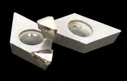
SCD stands for Single Crystalline Diamond. EHWA offers cutting tools with natural diamond, synthetic HPHT mono diamond and single crystalline CVD diamond. Tool design considers crystal orientation, the required cutting-edge contour and the machine interface.
The programme addresses precision machining of non-ferrous materials. Sharp, finely finished edges support mirror surfaces and machining with low burr formation. Tool life and cutting quality are matched to the workpiece, geometry and process. The illustrated tools are application-specific designs.
| Application | Machining task |
|---|---|
| Contact lenses | Finish inner and outer surfaces |
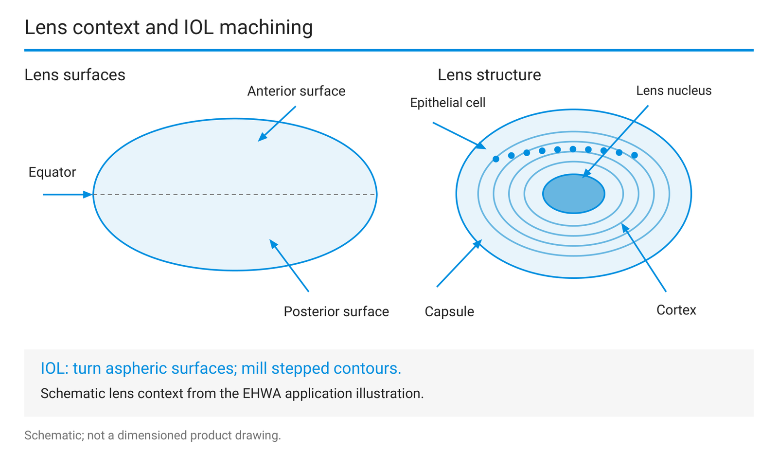
| Intraocular lenses (IOL) | Turn aspheric surfaces and mill stepped contours |
| Electro-optic components | Machine precision moulds for plastic aspheres |
| Display components | Light guide panels, polarising and prism pattern films; patterned copper rolls |
| Microstructures | Shape radii, produce grooves and make imprinting geometries |
| Spectacle lenses | Machine-specific SCD inserts for lens machining |
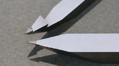
Contact lenses: match tool, edge and holder
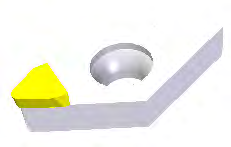
For contact-lens machining, EHWA lists natural and synthetic diamond, insert and solid-tool designs, and controlled or non-specified edge waviness. Cylindrical and conical clearance geometries are available. The diamond tip is high-vacuum brazed.
Edge inspection addresses microchipping at 1,000x magnification. The surface objective is finely finished inner and outer surfaces with low scratching and burr formation. Regrinding or relapping is offered as a tool service; suitability is assessed against the remaining geometry.
Contact-lens code and selection
| Feature | Code | Design |
|---|---|---|
| Diamond | EN | Natural diamond |
| Diamond | EM | HPHT mono diamond |
| Diamond | EV | Single crystalline CVD diamond |
| Insert shape | D | 55°; DCGW0702 or DCMW11T3 |
| Insert shape | V | 35°; VCGW1103 |
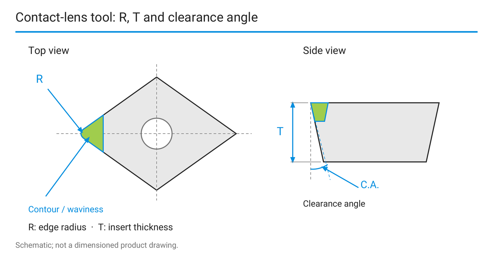
| Radius | R025; R03; R05 | R0.25; R0.3; R0.5 |
| Clearance angle | CA10; CA12; CA15; CA16; CA18 | 10°; 12°; 15°; 16°; 18° |
| Clearance geometry | CO; CY | Conical; cylindrical |
| Controlled edge waviness | W005 | ≤0.05 µm |
| Controlled edge waviness | W01 | ≤0.1 µm |
| Controlled edge waviness | W02 | ≤0.2 µm |
| Controlled edge waviness | W03 | ≤0.3 µm |
| Controlled edge waviness | W05 | ≤0.5 µm |
| Further waviness option | Without a controlled waviness class | Design according to radius and clearance geometry |
The source example EV-D-R03-CA15-CO-W03 identifies single crystalline CVD diamond, a DCGW0702 design, R0.3, 15° clearance angle, conical clearance geometry and class W03 with edge waviness ≤0.3 µm.
The special-design row for contact-lens tools lists single crystalline (110) 2pt diamond, radii 0.1-1.0 and clearance-angle codes CA01-CA20. Contour design depends on radius and clearance geometry. These details are specified with the tool drawing; the radius values in this table do not have an explicitly printed unit.
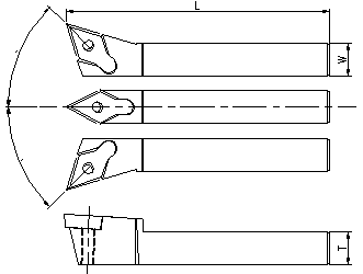
The holder system includes centre, right-hand and left-hand orientations with angle offset. Solid-tool and insert designs are available. Holder length, width and thickness can be matched to the interface; a tungsten-carbide shank is listed.


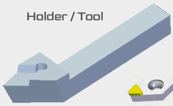
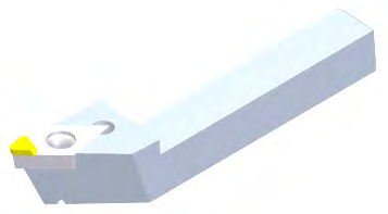
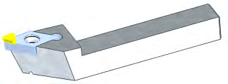
Intraocular lenses: turning and milling
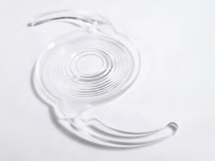
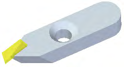
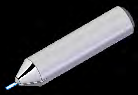
For IOL machining, EHWA offers SCD tools for aspheric turned surfaces and stepped milled contours. Diamond-edge position is matched to the machining task.
| Feature | Design |
|---|---|
| Diamond | Natural or synthetic diamond |
| Tool construction | Insert or solid-tool design |
| Process | Turning or milling |
| Clearance geometry | Cylindrical or conical |
| Diamond attachment | High-vacuum brazing |
| Edge inspection | Assess microchipping at 1,000x magnification |
SPC tools for plastic aspheres
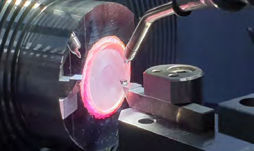
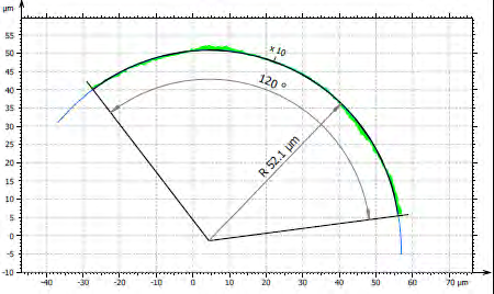
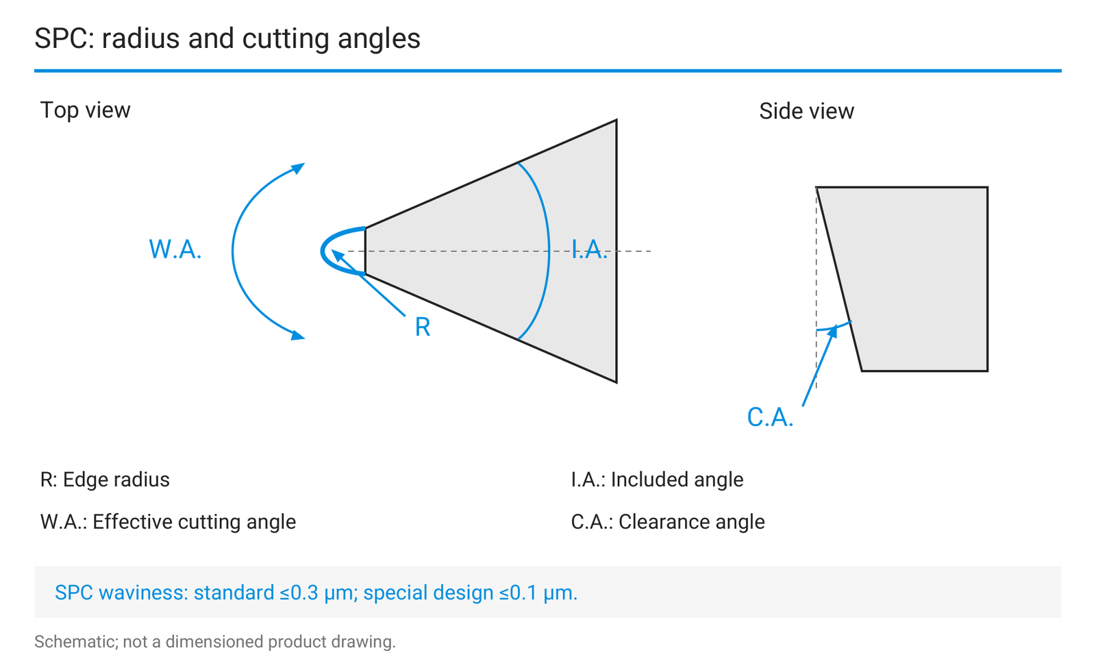
SPC stands for Super-Precision Cutting tools. The programme includes single crystalline diamond edges for machining high-precision lens moulds. The selection below separates standard and special designs; its values are not merged with the general SCD ranges.
| Geometry | Standard | Special design |
|---|---|---|
| Radius | 0.01-1.0 mm | <0.01 mm |
| Included angle I.A. | ≥30° | <30° |
| Effective cutting angle W.A. (Window Angle) | ≤100° | >100° |
| Clearance angle C.A. | ≤15° | >15° |
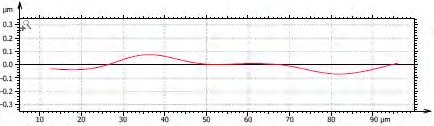
| Edge waviness / contour accuracy | ≤0.3 µm (300 nm) | ≤0.1 µm (100 nm) |
| Clearance geometry | Cylindrical or conical | Cylindrical or conical |
EHWA also lists edge waviness <50 nm as an available design. This application-specific option is agreed separately. It does not replace the table's standard and special classes. Dimensional and contour inspection form part of defining the required tool design.
Tools for display films and patterned rolls
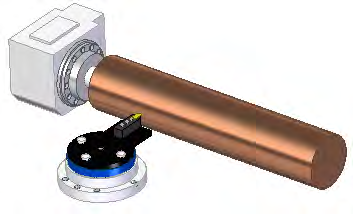
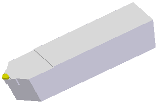
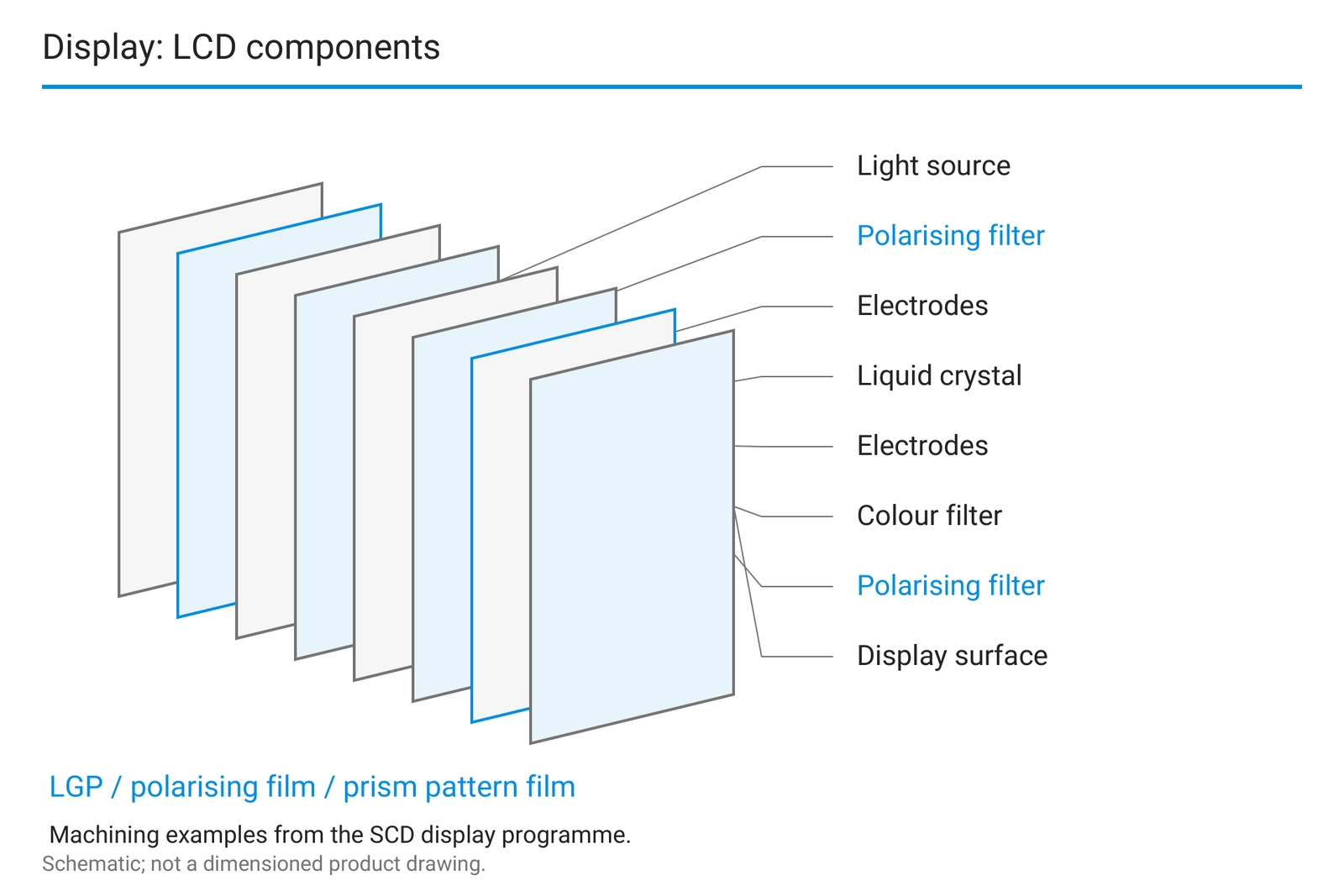
The display programme includes light guide panels (LGP), polarising films and prism pattern films. SCD tools are designed for mirror surfaces and machining large copper rolls for pattern films. Diamond orientation, edge profile and holder are matched to the required structure.


Microstructure tools: nine illustrated profiles
EHWA offers custom SCD tools for structure and pattern machining. The illustrated shapes comprise radius profiles, groove geometries and imprinting forms. The profile is defined from the required structure.
| Group | Illustrated design |
|---|---|
| Radius profiles | Small radius |
| Radius profiles | Large radius |
| Radius profiles | Engraving radius |
| Groove geometries | V-shaped |
| Groove geometries | Microgroove |
| Groove geometries | Chamfered groove |
| Groove geometries | Chamfer with a radiused edge |
| Imprinting forms | Angled punch shape |
| Imprinting forms | Conical punch shape |
The profile images show the design types. They contain no binding dimensions; radii, angles and profile dimensions are specified against the drawing.






Spectacle-lens machining: designs for Satisloh and Schneider
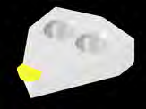
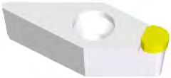
The SCD document shows five machine-related insert designs. Part numbers and the two Schneider angle variants are retained separately. Machine, interface and required geometry are checked together before specifying the tool.
| Machine assignment | Source part number | Edge | Radius designation | Further geometry |
|---|---|---|---|---|
| Satisloh VFT | 92-007-626 | Single crystalline diamond | R2.0 | - |
| Satisloh | 92-06-3012 | Single crystalline diamond | R2.0 | - |
| Satisloh | No part number printed | Single crystalline diamond | R2.0 | Twin hole; 120° Window Angle |
| Schneider | DB-07-2003 | Single crystalline diamond | R2.0 | 120° Window Angle |
| Schneider | DB-07-2003 | Single crystalline diamond | R2.0 | 90° Window Angle |
R2.0 is retained as the source radius designation. Unit and fit are specified using the controlling tool drawing. The machine and part-number assignments document EHWA's design examples.



Supplementary GT codes for optical lenses
The supplementary EHWA document Q223 lists three GT codes for spectacle and free-form lenses. It states edge inspection at 800x magnification and a regrinding service. These codes are retained as distinct source cards.
| Machine assignment | EHWA code | Source-card description | Source manufacturer part number |
|---|---|---|---|
| Satisloh VFT | GT-92-007-626 | Monocrystalline insert; turning tip MCD, R2 mm | 92-007-626 |
| Schneider | GT-DB-07-2003 | Monocrystalline insert; 120° Included Angle | Call Us |
| Schneider | GT-DB-07-2004 | Monocrystalline insert; 90° Included Angle | Call Us |
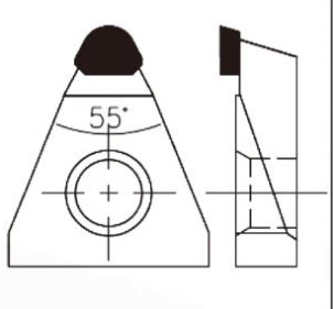
The Satisloh source drawing shows 55°. The GT card expressly specifies radius R2 mm. Both Schneider cards use the term Included Angle; Q269 labels the angles of its designs as Window Angle. These source descriptions remain separate and are checked against the controlling tool drawing. GT-DB-07-2004 is not silently renamed to manufacturer part number DB-07-2003.
Technical source: Q223, physical PDF page 21. The remaining content of this trade-show document belongs to the consolidated cutting-tool programme.
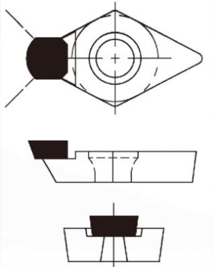
General SCD geometry and design code
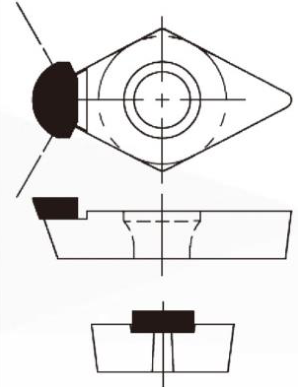
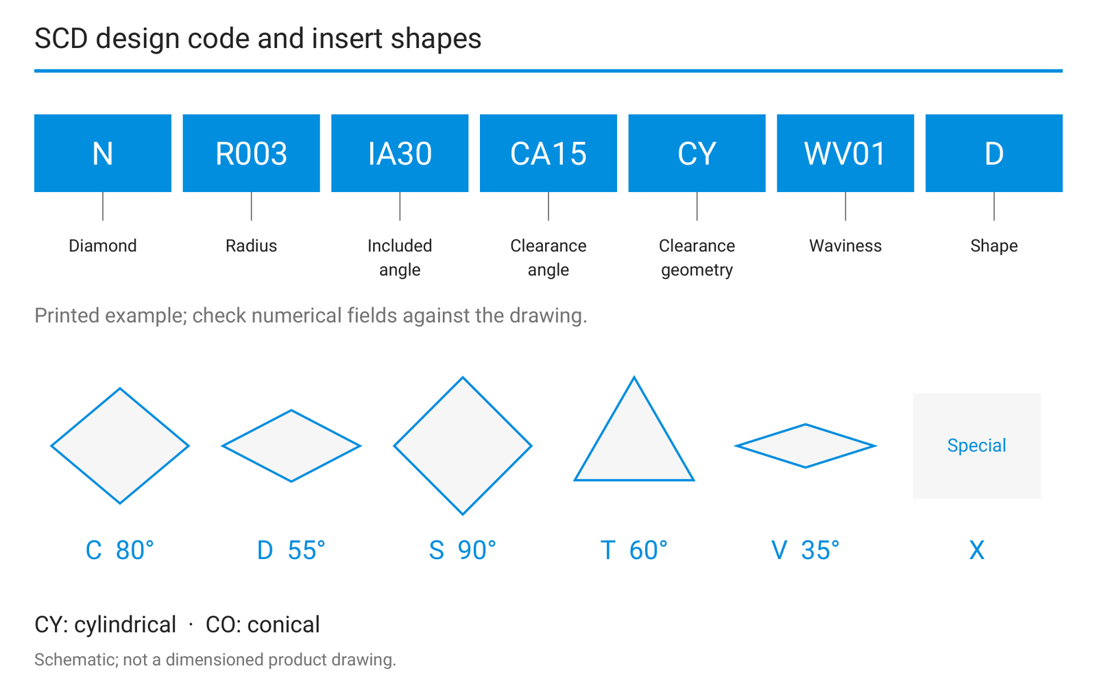
The general SCD overview distinguishes diamond, radius, included angle, clearance angle, clearance geometry, edge waviness and insert shape. The printed code example is N-R003-IA30-CA15-CY-WV01-D. Individual fields are checked against the drawing when enquiring; numerical encoding is not fully explained for every field.
| Feature | Printed range or selection |
|---|---|
| Diamond | Natural diamond; Mono; SCVD |
| Standard radius | 0.1 ≤ R ≤ 10 |
| Special radius | 0.0005 ≤ R < 0.1 |
| Standard I.A. | 30° ≤ I.A. ≤ 180° |
| Special I.A. | I.A. <30° |
| Clearance angle C.A. | 0° ≤ C.A. ≤ 25° |
| Clearance geometry | CY: cylindrical; CO: conical |
| Waviness classes | ≤0.05 µm (50 nm); ≤0.1 µm (100 nm); ≤0.3 µm (300 nm); ≤1.0 µm; ≤2.0 µm |
| Shape C | 80° |
| Shape D | 55° |
| Shape S | 90° |
| Shape T | 60° |
| Shape V | 35° |
| Shape X | Special shape |
The general overview prints no unit for the radius limits. The separate SPC table specifies millimetres. Tool ordering therefore uses the corresponding drawing with its unit.
EHWA describes conical clearance geometry as providing a circular contour and a comparatively weaker edge structure; regrinding reduces the radius. Cylindrical clearance geometry is described with an elliptical effect, a comparatively stronger edge structure and a constant radius after regrinding. Selection considers the contour objective and reconditioning strategy.
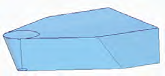
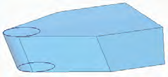
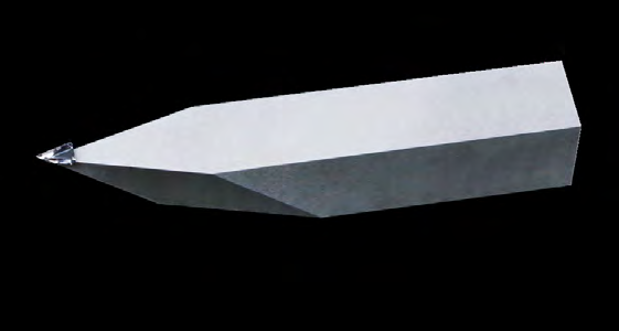
Edge and profile inspection
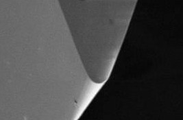
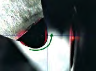
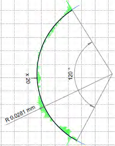
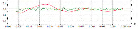
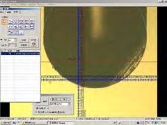
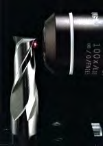
EHWA lists microscopy, scanning electron microscopy (SEM) and 3D measurement for assessing contour accuracy, roughness, profile and further dimensions. Edge inspection shows examples at 50x and 500x magnification; application-specific features additionally mention inspection at 1,000x. Profile analysis of rotating tools is illustrated using 3D measurement.




Match your precision application
An enquiry benefits from a workpiece drawing, material, hardness (HRC / HRB / HB), target roughness (Ra / Rz / Rmax), machine manufacturer, interface and machining process. Add cutting speed in m/min, spindle speed in rev/min, feed in mm/rev or mm/min, depth of cut in mm and the number of passes.
Describe continuous or interrupted cutting; the EHWA enquiry fields distinguish light, medium and heavy interruption. State dry machining or internal or external coolant supply. Tool life can be recorded using operating time and piece count.
Tool information comprises specification, comparison tool, cutting material and shank. The SCD enquiry sheet lists natural diamond, Mono and SCVD, as well as PCD, PCBN, CVD and further cutting materials; shanks include carbide, steel, carbide/steel, SUS stainless steel, titanium or other materials. Processes include turning, milling, boring, grooving/parting, reaming, endmilling, drilling and wear-part applications; an undecided process assignment can be defined together.
EHWA Europe: info@ehwadia.de · +49 6173 997780
Editorial date: 14 October 2026. Technical basis: EHWA SCD, 14 pages, printed 2024.07. Earlier SCD editions and short SCD/Wear Parts overviews were checked for unique content.
Questions about tool selection
Which diamond tools are intended for lens machining?
EHWA describes SCD tools with natural diamond, HPHT mono diamond and single crystal CVD diamond for contact lenses, intraocular lenses and plastic aspheres. Edge contour, radius, angles and interface are specified together with the machining task.
Does the SCD catalogue include tools for Satisloh and Schneider?
Yes. The design overview includes machine-related SCD inserts and GT cards for Satisloh and Schneider. Part number, radius designation and the respective angles are listed separately; the interface is specified using the tool drawing.