EHWA DIAMOND – since 1975
Glass, display, LED and solar: coordinated machining
EHWA combines diamond grit, bond, tool profile and manufacturing method with the requirements of glass, silicon, sapphire and other hard materials. The programme covers cutting and edge machining, lapping and polishing, and wafer machining. It supports display and mobile-device production, LED and solar applications, and automotive, home-appliance, architectural and optical glass.
Tool design depends on material, glass or wafer thickness, machine, mounting method, machining stage and surface target. The sheets contain several programme versions: different diameters, grit ranges, wire codes and test conditions remain separate variants. The documented comparisons support selection; their results refer to the illustrated application.
Editorial edition: 13 October 2026. The date identifies this German–English compilation. EHWA Europe is available to support the specific tool design.
Tools for automotive, home-appliance, architectural and optical glass
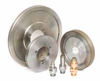
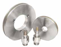
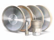
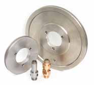
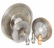
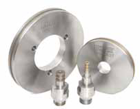
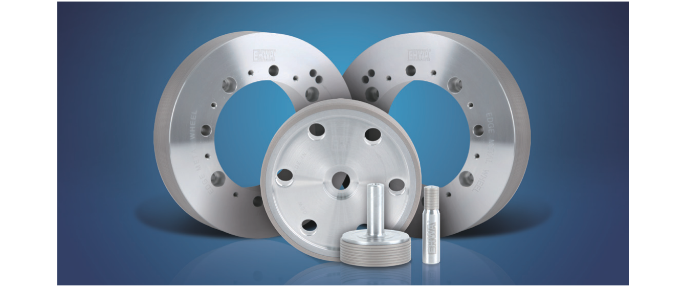
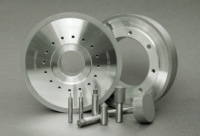
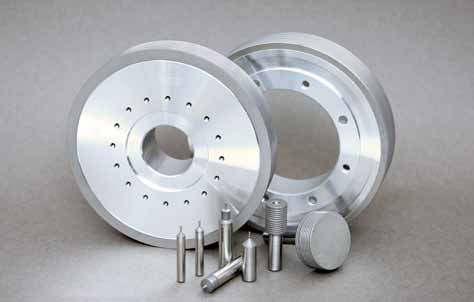
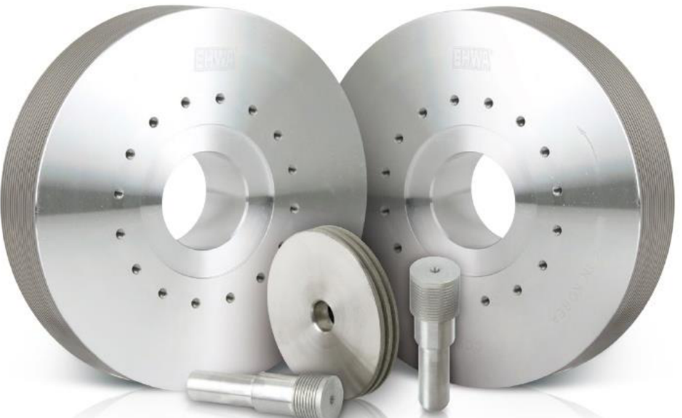
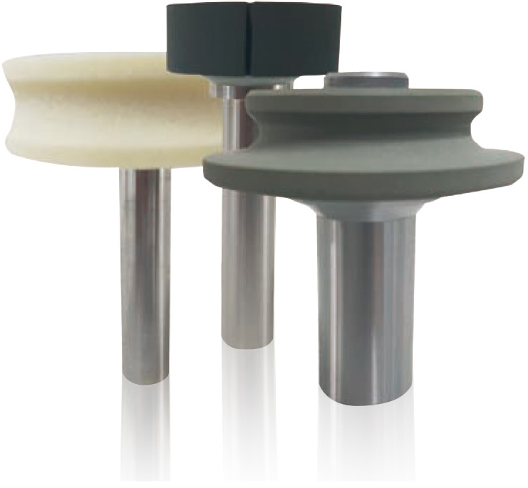
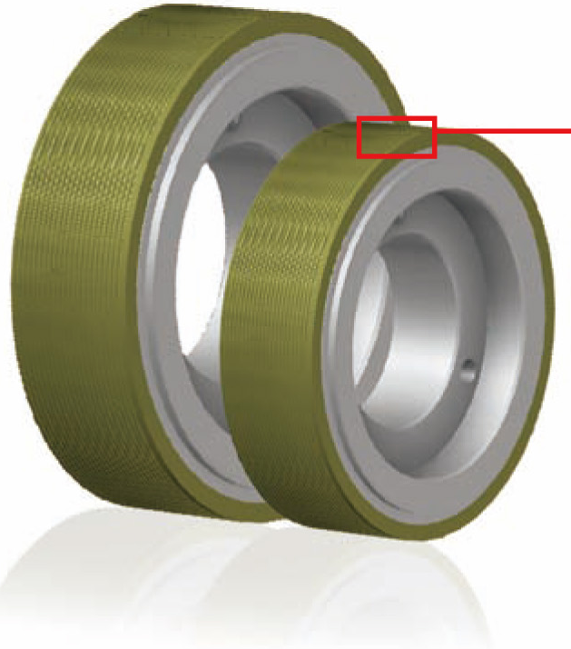
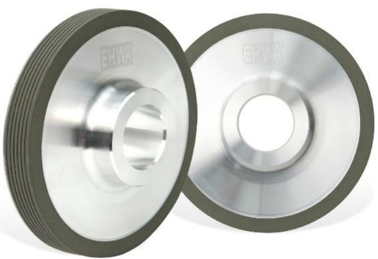
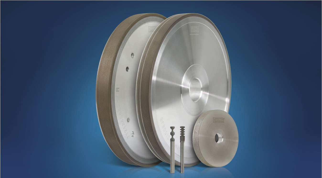
The glass tools include profiles for automotive glazing, home appliances and architectural glass, and versions for optical lenses and crystal glass. The illustrations show wheels, multi-groove profiles and shank tools. Specific applications include side mirrors, glass holes and home-appliance glass edges.
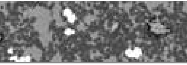
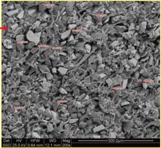
For automotive glass, the programme lists three bond characters in the same D107~D30 grit range: MB softer, MC standard and MG harder. This allows tool selection to match the machining task. The micrographs show the corresponding versions.
| Series | Grit size | Bond character |
|---|---|---|
| MB | D107~D30 | Softer |
| MC | D107~D30 | Standard |
| MG | D107~D30 | Harder |



Home-appliance glass: new and refurbished tools
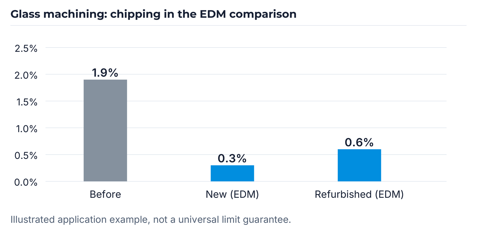
The developed wheels are designed for strong edge quality and reduced chipping. The illustrated EDM comparison shows 1.9% before the change, 0.3% with the new tool and 0.6% with the refurbished tool. The source describes a value below 1% after refurbishment. The tool design is matched to your glass and process.
| Comparison condition | Chipping [%] |
|---|---|
| Before | 1.9 |
| After: new (EDM) | 0.3 |
| After: refurbished (EDM) | 0.6 |
Optical lenses: roughing, finishing and polishing
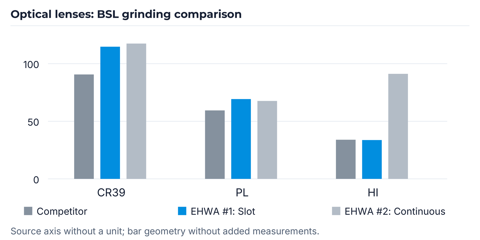
The optical programme distinguishes GL roughing with MD-1A1, PL roughing with MD-BSL, and finishing and polishing with MD-1EE6Y. Grit ranges remain separate for each stage. The BSL Slot (#1) and Continuous (#2) versions are compared with a reference tool for CR39, PL and HI. The numerical axis has no stated unit; the bars show the relative performance comparison.
| Process | Type | Grit size |
|---|---|---|
| Roughing (GL) | MD-1A1 | D251~D151 |
| Roughing (PL) | MD-BSL | D301~D151 |
| Finishing | MD-1EE6Y | D46~D30 |
| Polishing | MD-1EE6Y | D2 |



Metal-bond edge tools for LCD and OLED
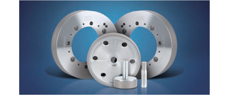
Metal-bond tools provide different groove profiles, uniform chamfer widths and strong profile retention. Roughing and finishing can be combined in one tool version. The programmes are designed for LCD/OLED panels and glass edges.
The first version lists MD-DW with Ø8~Ø100 and MD-1FF6Y with Ø40~Ø200 and #325~#3000. Its panel test additionally states wheel wear of 35~40 µm. The second version lists Ø5~Ø50 and Ø50~Ø200 and #325~#2000; its comparison explicitly refers to a 15-inch panel. These versions are not combined into one dimensional range.
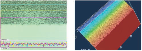
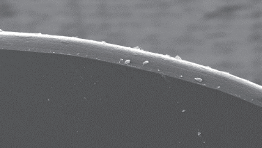
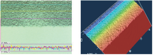
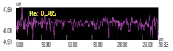
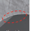
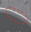
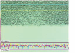
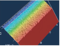
The measurement images supplement edge strength, tool life and chipping size. They retain their profile axes and topography annotations. The additional profile is labelled Ra 0.385; its visible source annotations remain authoritative without turning this into a universal product specification.
| Type | Diameter (source notation) | Thickness [mm] | Grit size | Bond |
|---|---|---|---|---|
| MD-DW | Ø8~Ø100 | 5~20 | #325~#3000 | Metal |
| MD-1FF6Y | Ø40~Ø200 | 5~80 | #325~#3000 | Metal |
| Application | Edge strength [MPa] | Lifetime [cells/groove] | Wheel wear [µm] | Chipping size [µm] |
|---|---|---|---|---|
| Panel grinding | 120~130 | 100 | 35~40 | <30 |
| Type | Diameter (source notation) | Thickness [mm] | Grit size | Bond |
|---|---|---|---|---|
| MD-DW | Ø5~Ø50 | 5~20 | #325~#2000 | Metal |
| MD-1FF6Y | Ø50~Ø200 | 5~80 | #325~#2000 | Metal |
| Application | Edge strength [MPa] | Lifetime [cells/groove] | Chipping size [µm] |
|---|---|---|---|
| 15-inch panel grinding | 120~130 | 100 | <30 |








Electroplated edge-grinding tools: double and triple mesh
Controlled diamond distribution and an appropriate grit size and concentration support consistent tool quality and clean edges. Precision electroplating is designed for dimensional accuracy and uniform profiles. The tools machine LCD/OLED panels, smartphone cover glass, and sapphire and silicon wafer edges.
The earlier double-mesh version combines roughing and finishing and states 50% longer life in its illustrated competitor comparison. A further version offers double and triple mesh. ED-DW diameters differ between Ø0.5~Ø100 and Ø0.5~Ø40. ED-1FF6Y is listed with Ø20~Ø300. The product presentation explicitly lists DW-1FF6Y at this position; that source designation is retained.
The ten edge images compare EHWA and the reference tool at 325, 400, 600, 800 and 1000 mesh. The red source markers remain visible in the comparison images. The example documents this machining condition and does not replace application-specific tool-life or edge-quality validation.
| Type | Diameter (source notation) | Grit size | Bond |
|---|---|---|---|
| ED-DW | Ø0.5~Ø100 | #100~#1500 | Electroplated |
| ED-1FF6Y | Ø20~Ø300 | #100~#1500 | Electroplated |
| Type | Diameter (source notation) | Grit size | Bond |
|---|---|---|---|
| ED-DW | Ø0.5~Ø40 | #100~#1500 | Electroplated |
| ED-1FF6Y | Ø20~Ø300 | #100~#1500 | Electroplated |
| Type | Diameter (source notation) | Grit size | Bond |
|---|---|---|---|
| ED-DW | Ø0.5~Ø100 | #100~#1500 | Electroplated |
| DW-1FF6Y | Ø20~Ø300 | #100~#1500 | Electroplated |
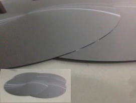
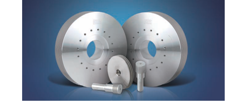



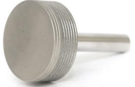
Scribing wheels for glass and displays
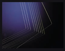
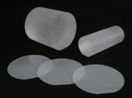
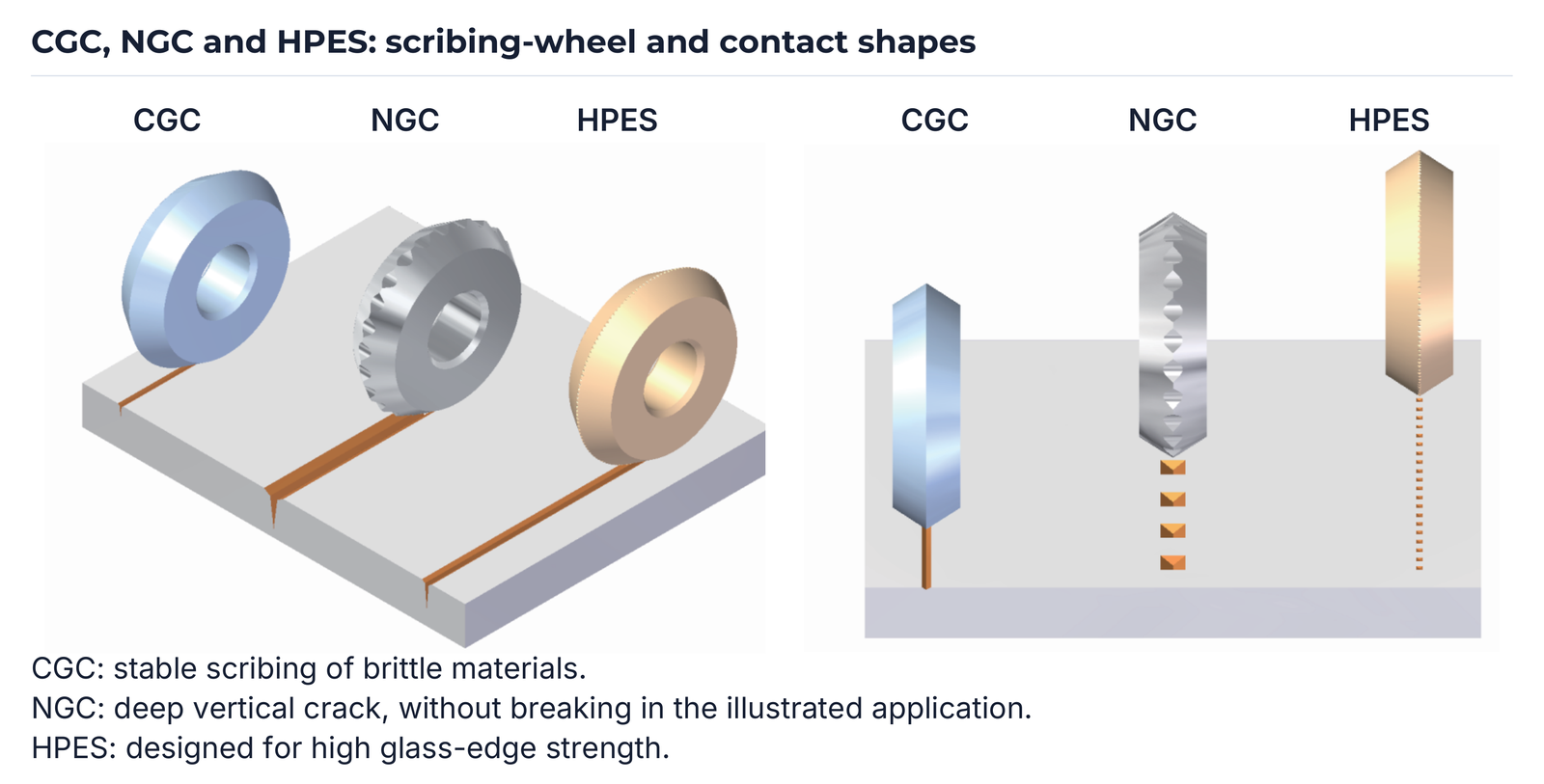
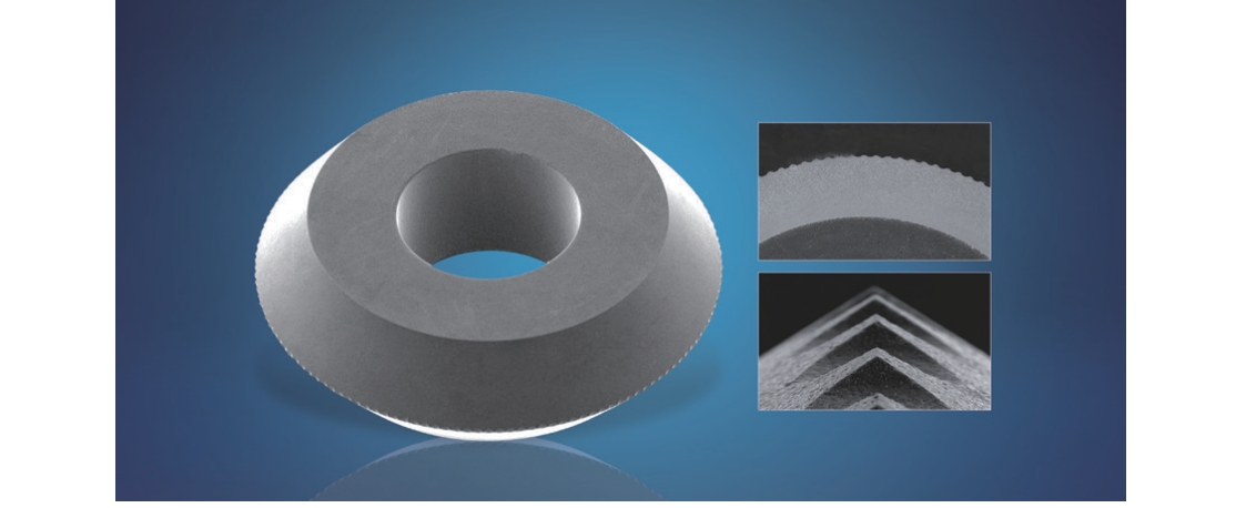
Automated manufacturing supports consistent scribing performance. The wheels are designed for low defects and high glass-edge strength across different glass thicknesses. CGC supports stable scribing of brittle materials; NGC creates a deep vertical crack and can be used without a separate breaking step in the illustrated application. HPES is designed for high edge strength.
Angle, notch count and notch depth are matched to glass thickness and application. The older six-row table ends at ~0.2 mm; the product presentation lists ~0.1 mm in the same final row. Both versions are retained. No unit is stated for notch depth.
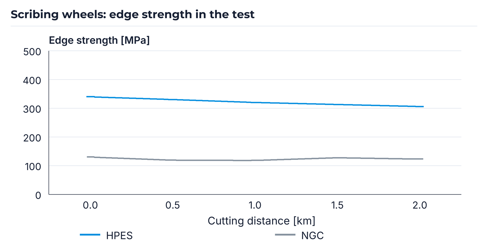
The comparison curve shows edge strength [MPa] over cutting distance [km] for NGC and HPES. It retains the source curve geometry without estimated individual measurements. Glass type, scribing force, speed and angle affect crack formation and edge quality; wheel selection is matched to this process.
| Glass thickness [mm] | Angle | Number of notches | Notch depth (source unit unstated) | Application |
|---|---|---|---|---|
| 1.0~ | 125°~150° | 80~140 | 9~15 | Automotive glass, solar cells |
| 0.5~ | 115°~125° | 135~140 | 10 | TFT LCD |
| 0.4~ | 105°~115° | 135~170 | 5.5~10 | PDP glass for TV/monitor |
| 0.3~ | 100°~110° | 150~400 | 3.5~7 | TFT LCD / AMOLED for mobile devices |
| 0.2~ | 95°~105° | 200~600 | 2~3 | TFT LCD / AMOLED for mobile devices |
| ~0.2 | 90°~100° | 50~720 | 1.5~3 | FPD, mobile cells |
| Glass thickness [mm] | Angle | Number of notches | Notch depth (source unit unstated) | Application |
|---|---|---|---|---|
| 1.0~ | 125°~150° | 80~140 | 9~15 | Automotive glass, solar cells |
| 0.5~ | 115°~125° | 135~140 | 10 | TFT LCD |
| 0.4~ | 105°~115° | 135~170 | 5.5~10 | PDP glass for TV/monitor |
| 0.3~ | 100°~110° | 150~400 | 3.5~7 | TFT LCD / AMOLED for mobile devices |
| 0.2~ | 95°~105° | 200~600 | 2~3 | TFT LCD / AMOLED for mobile devices |
| ~0.1 | 90°~100° | 50~720 | 1.5~3 | FPD, mobile cells |



Edge polishing with polyurethane and cerium oxide
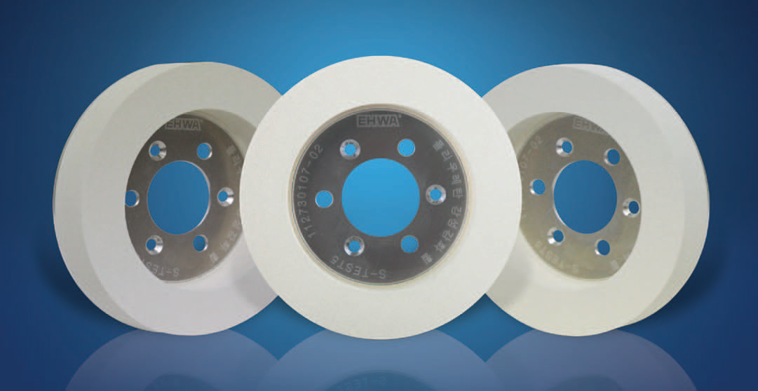
Edge-polishing wheels for mobile LCD and OLED panels combine removal performance, surface quality and usable life. The compliant polishing action supports strong edges. The sheets describe longer life and fewer tool changes than their comparison wheel, aiming for lower consumable cost and high throughput.
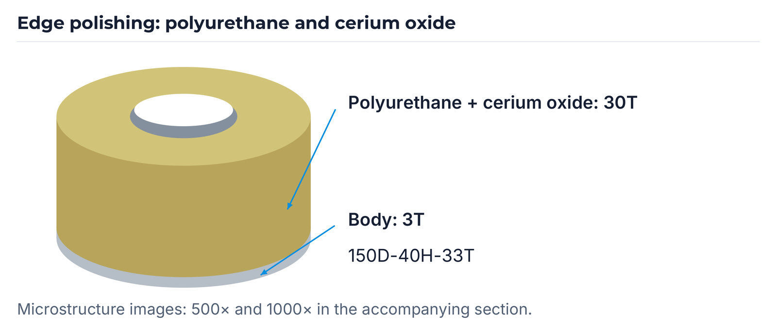
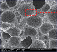
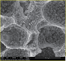
The illustrated version carries the size designation 150D-40H-33T. The polyurethane/cerium-oxide layer is designated 30T and the body 3T. Two microstructure images at 500× and 1000× show the structure and retain their source scales.
| Feature | Designation / value |
|---|---|
| Size designation | 150D-40H-33T |
| Polyurethane + cerium oxide | 30T |
| Body thickness | 3T |
| Microstructure magnifications | 500× / 1000× |
Polishing tools for glass, aluminium cases and cutting edges
Foam pads, polyurethane groove wheels, brushes and resin diamond tools extend the polishing programme. Applications range from aluminium mobile-device cases and glass to SUS machining on smartwatch backs. The table retains the different abrasives and the #800 version.
Polyurethane can reduce glass chipping after metal-bond machining. Its elasticity supports fine grinding and polishing; hardness and abrasive content can be adjusted. The hard version shows local marks of 66.67, 74.83 and 61.22 µm after metal #500 and 6.94 µm after EHWA polyurethane polishing. The sheet itself notes that chamfer quality depends on the process recipe.
For cutting edges, the product presentation describes improved roughness, easier chip evacuation, cutting ability and life, and strong chamfer surfaces. Its specific polishing example shows Ra 1.476 µm before and Ra 0.337 µm after polishing. The bond is polyurethane, with diamond #400~#1200 and SiC #400~#1500 abrasive ranges.
| Tool | Abrasives / grit size | Application |
|---|---|---|
| Polyurethane sponge pad (foam type) | Diamond, SiC, Al₂O₃, CeO₂ | Polishing aluminium mobile-device cases |
| Polyurethane groove wheel | Diamond, SiC | Glass machining |
| Brush, DW type | Diamond, SiC, Al₂O₃ | Polishing aluminium mobile-device cases |
| Resin diamond wheel | Diamond #800 | Smartwatch back side, SUS grinding |
| Surface / tool | Printed local measurements |
|---|---|
| After metal #500 | 66.67 µm / 74.83 µm / 61.22 µm |
| After EHWA polyurethane wheel | 6.94 µm |
| Feature | Value |
|---|---|
| Bond | Polyurethane |
| Diamond grit | #400~#1200 |
| SiC grit | #400~#1500 |
| Ra before polishing | 1.476 µm |
| Ra after polishing | 0.337 µm |


Iron–resin lapping plates for sapphire and silicon
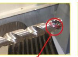
Iron–resin plates are described for precision lapping of patterned sapphire, bare sapphire and bare silicon substrates. Strong ductility supports low-damage machining. The sheet highlights removal performance, life and thermal stability, linking these properties to uniform, finely machined wafer surfaces.
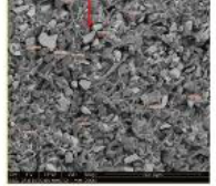
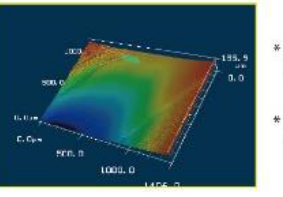
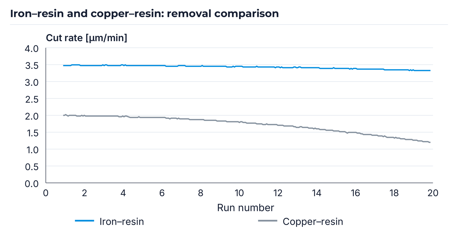
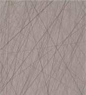
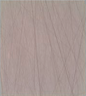
The programme table states cut rate as 2.5~5.0 µm without a time denominator. The separate test curve uses µm/min. Both statements retain their own context. The test compares iron–resin and copper–resin at 400 g/cm², 90 rpm and a slurry flow of 4 ml/min. The 50× images supplement the surface comparison after lapping.
| Application | Outside diameter [mm] | Inside diameter [mm] | Thickness [mm] | Cut rate [µm] |
|---|---|---|---|---|
| Sapphire-wafer lapping | Ø510~Ø1100 | Ø50~Ø500 | 12~25 | 2.5~5.0 |
| Parameter | Condition |
|---|---|
| Pressure | 400 g/cm² |
| Plate speed | 90 rpm |
| Polisher | Single-head type |
| Wafer | 4-inch single-crystal sapphire wafer |
| Plate comparison | Copper–resin / iron–resin |
| Slurry primary particle diameter | 3 µm |
| Slurry flow rate | 4 ml/min |
| Surface comparison | 50× |
Zenesis core drills for ingots and ceramic substrates
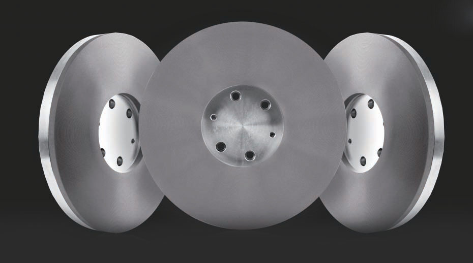
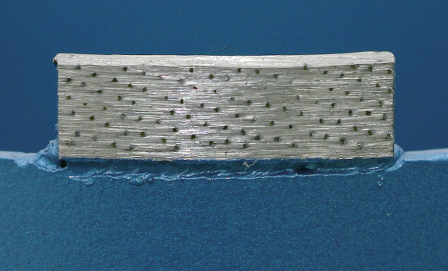
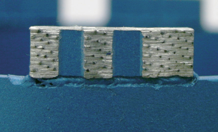
The Zenesis concept uses patterned diamond arrays and alternating diamond layers. Diamond exposure height, diamond-tail length and debris-clearance channels can be matched to the workpiece. The aim is high cutting speed, long life, low tool-to-tool variation and economical volume production with consistent performance throughout usable life.
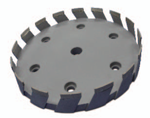
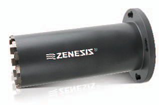
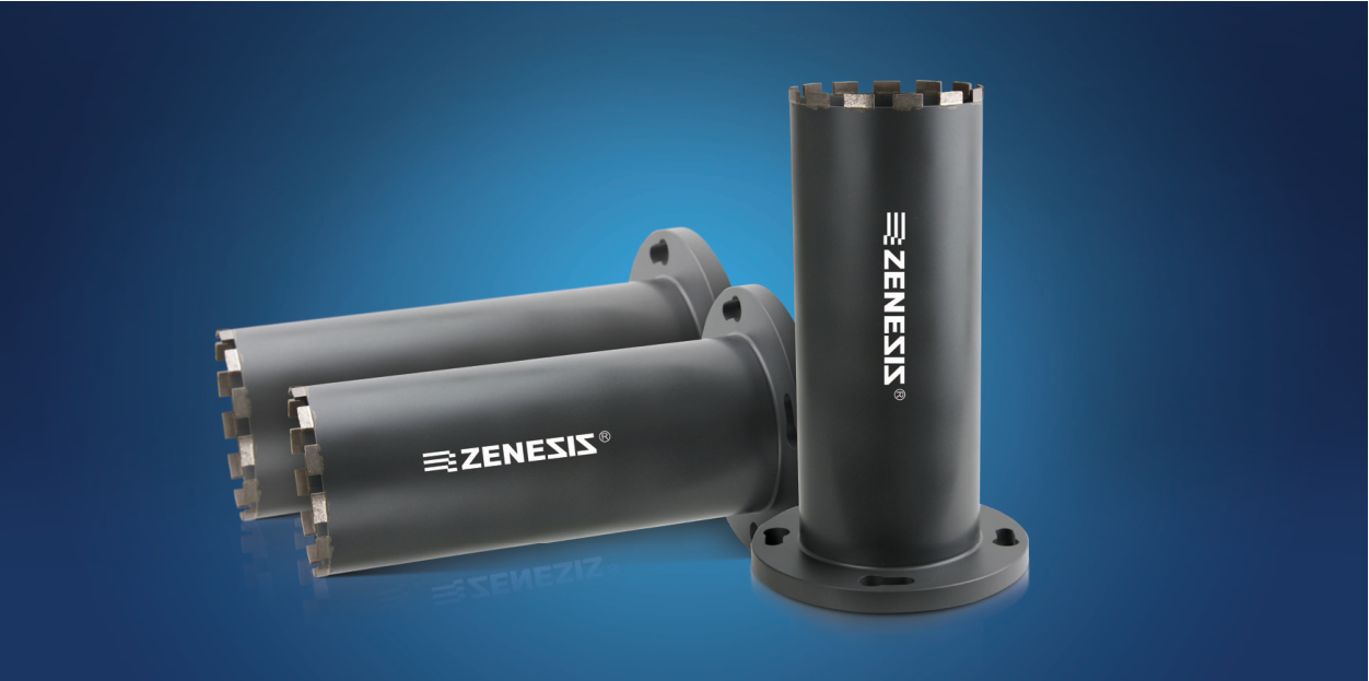
The sheet lists sapphire and silicon ingots and ceramic substrates. Zenesis turbo is shown alongside the Zenesis segment version. The programme lists 2″, 4″, 6″ and 8″ and a length of ~500 without a printed unit. The connection is literally stated as 1/2 BSP, 11/14 UNC; further connections are available on request. The unusual UNC designation is checked against the connection drawing before ordering.
The alumina/SiC substrate and susceptor example states a reduction from 4 to 2 hours when increasing outside diameter from Ø2–Ø10 to Ø203. The example does not print a unit for diameter. For ingots, the source describes long life and low current. These examples illustrate their specific tool designs and are not transferred to every workpiece.
| Diameter | Length (source unit unstated) | Connection (source notation) | Tip type |
|---|---|---|---|
| 2″, 4″, 6″, 8″ | ~500 | 1/2 BSP, 11/14 UNC; further connections on request | Zenesis / Zenesis turbo |
Silicon and sapphire wafers: edge profile and groove quality
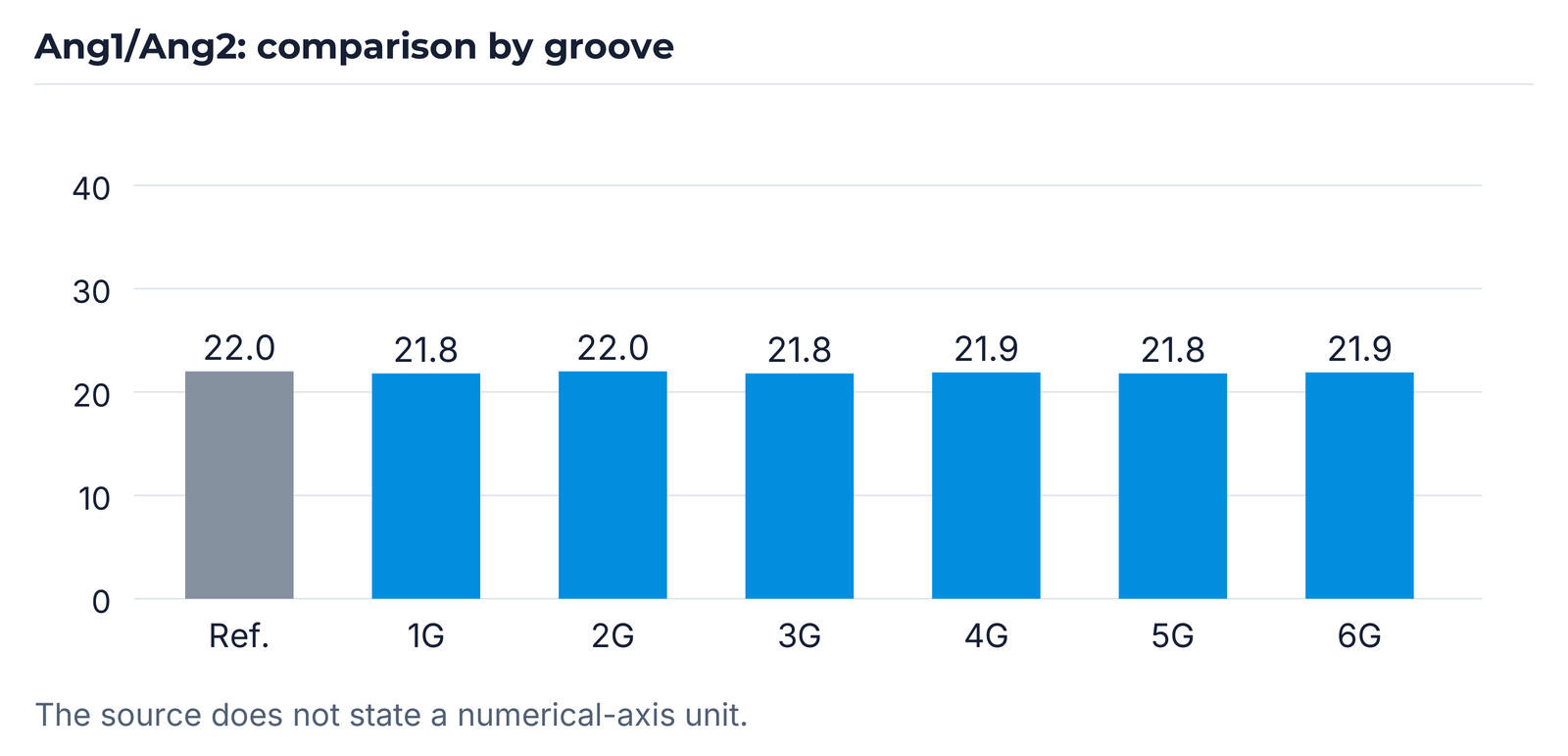
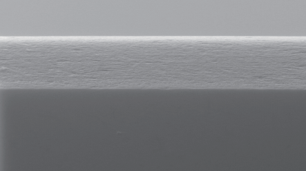
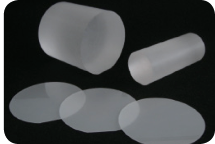
The tools combine adaptable groove shapes, uniform chamfer width and strong profile retention. Roughing and finishing can be combined in one version. Applications are silicon and sapphire wafer edges. The examples show sapphire and silicon surfaces and the geometric references A1/A2, B1/B2, Ang1/Ang2 and R.
The first programme table contains two groove columns listing 5G and 8G. A further edition lists 8G~10G in the last groove column for MD-1FF6Y. Diameters Ø3.9 and Ø202, thickness 5~20 mm and #325~#3000 remain unchanged. The diameter column has no unit in its heading.
The three charts compare the reference with 1G through 6G using A1/A2, Ang1/Ang2 and R. The numerical axes in the underlying sheet do not state a unit.
| Type | Diameter (source unit unstated) | Grooves 1 | Thickness [mm] | Grit size | Grooves 2 |
|---|---|---|---|---|---|
| MD-DW | Ø3.9 | 5G | 5~20 | #325~#3000 | 5G |
| MD-1FF6Y | Ø202 | 8G | 5~20 | #325~#3000 | 8G |
| Type | Diameter (source unit unstated) | Grooves 1 | Thickness [mm] | Grit size | Grooves 2 |
|---|---|---|---|---|---|
| MD-DW | Ø3.9 | 5G | 5~20 | #325~#3000 | 5G |
| MD-1FF6Y | Ø202 | 8G | 5~20 | #325~#3000 | 8G~10G |






Sapphire, SiC, glass and ceramics: back grinding
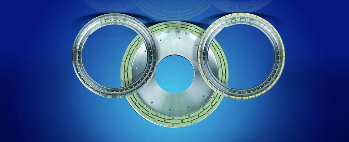
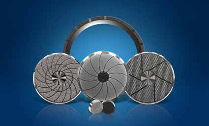
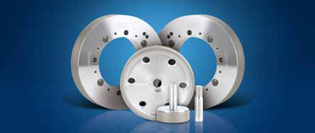
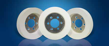
Metal-bond rough-grinding tools are designed for long life and high bulk removal. Vitrified fine-grinding tools support grinding performance and fine surfaces. Appropriate wheel designs are offered for different machines, grinding methods and process recipes. Applications include sapphire, SiC, glass and other hard materials such as zirconia.
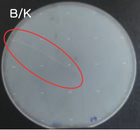
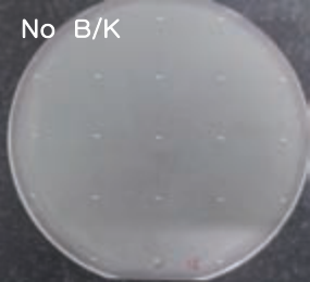
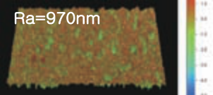
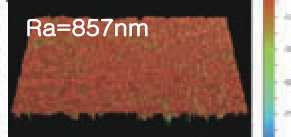
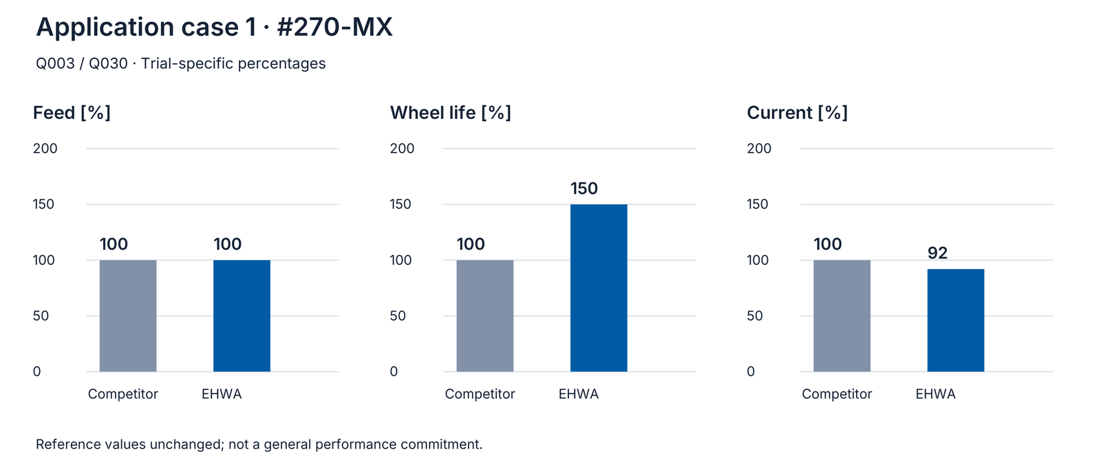
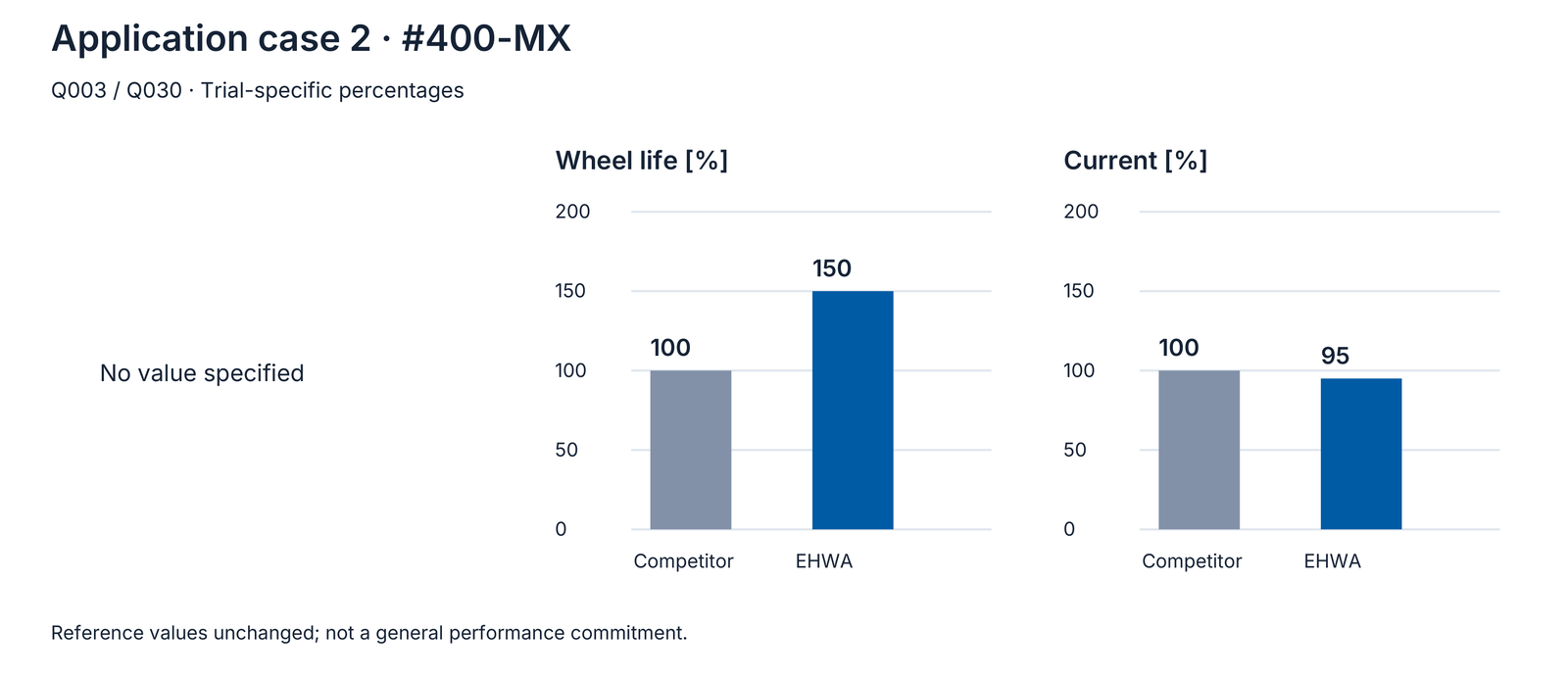
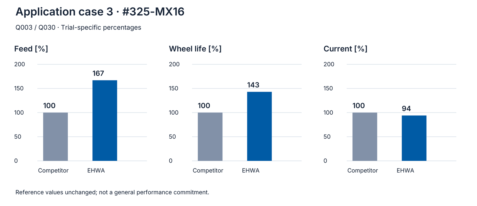
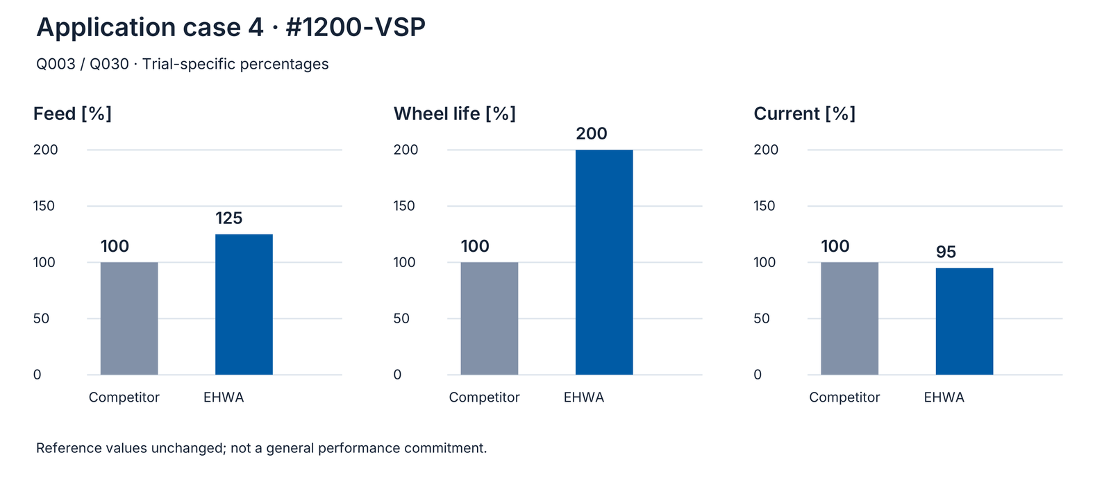
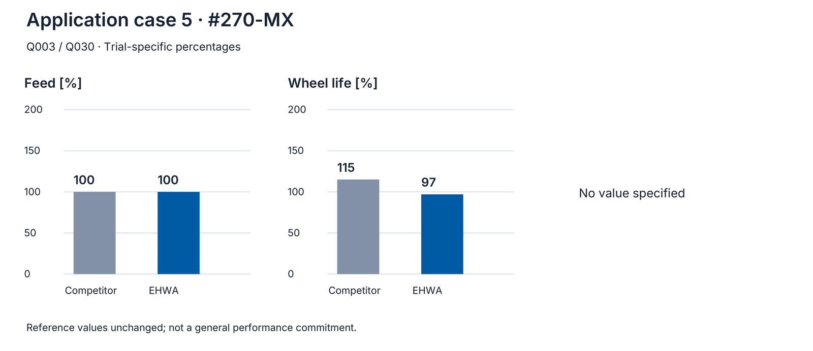
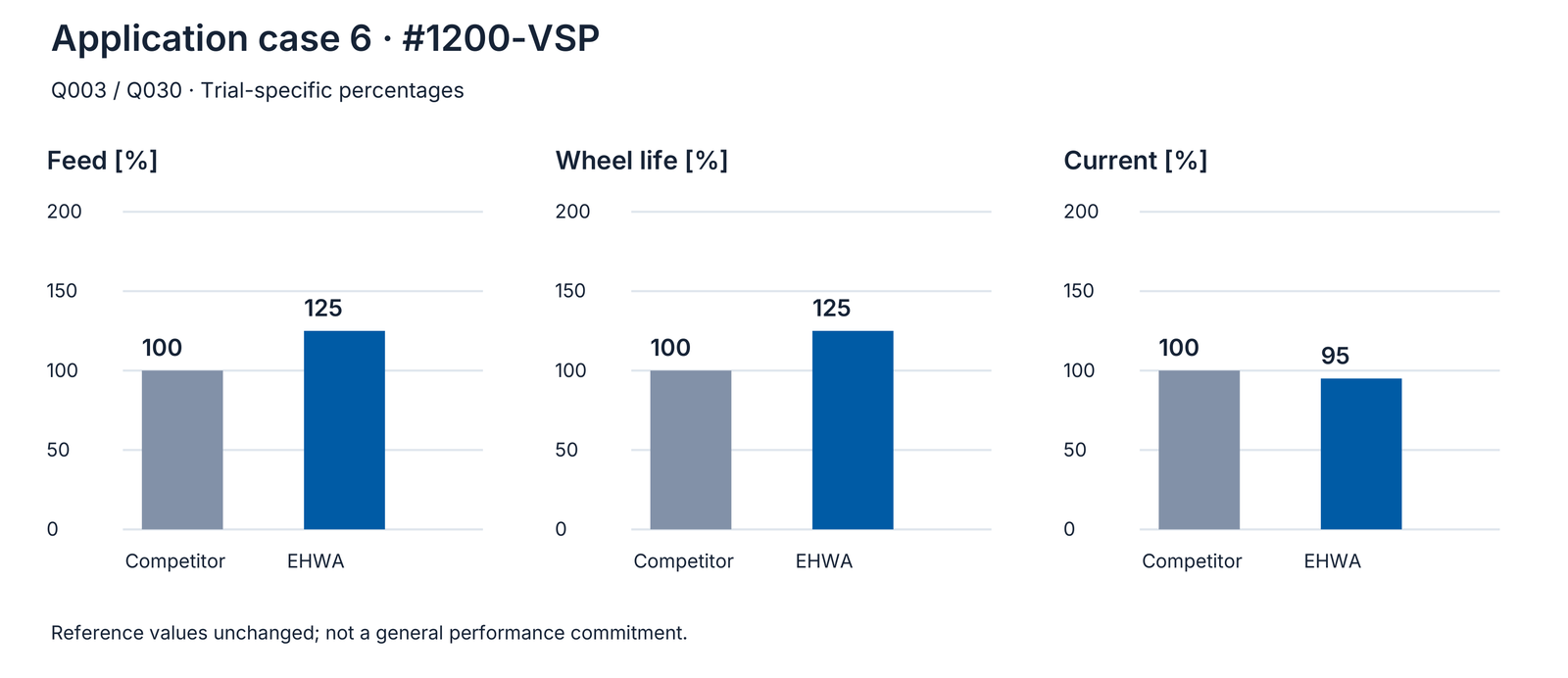
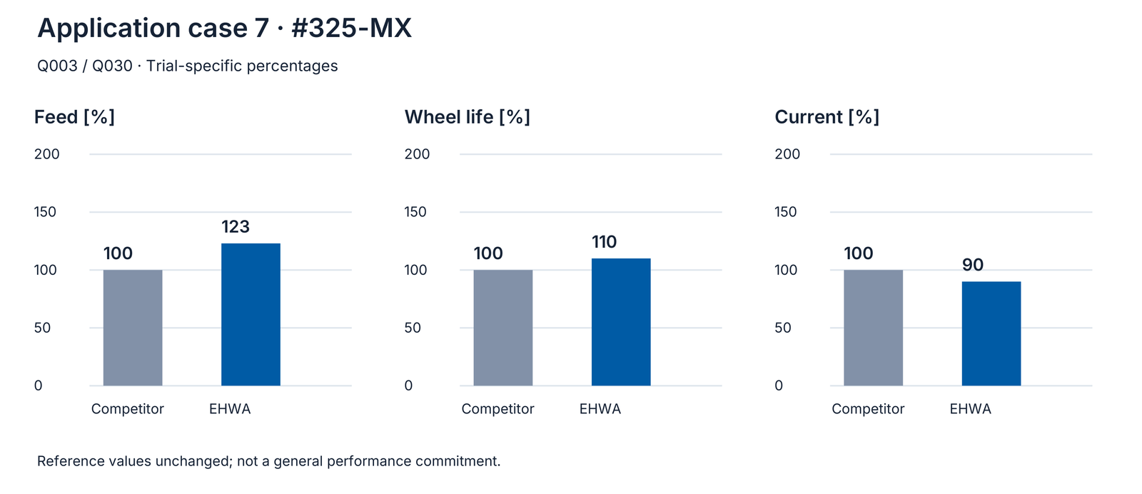
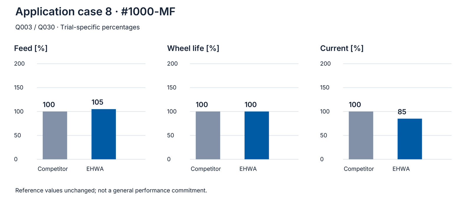
The eight examples distinguish 2–4″ sapphire on WAX, fully automatic 4″ sapphire on WAX, 6″ sapphire on TAPE and 8″ ceramic on TAPE. Comparison figures are ordered reference tool / EHWA. The 6″ roughing tool-life values explicitly remain 115 / 97; missing values remain absent rather than zero. The wafer/surface pairs are labelled B/K and No B/K and Ra 970 nm and Ra 857 nm.
| Stage | Series | D [mm] | W [mm] | X [mm] | Grit size | Shape |
|---|---|---|---|---|---|---|
| Rough | MX / MS Series | 200~300 | 3~5 | 3~10 | #170~#500 | Slant / Segment |
| Fine | MS / VSP / VSBT Series | 200~300 | 3~5 | 3~10 | #600~#5000 | Slant / Segment |
| Case | Wafer / mounting | Tool | Feed rate [%] | Tool life [%] | Current [%] |
|---|---|---|---|---|---|
| 1 | 2~4″ sapphire / WAX | #270-MX | 100 / 100 | 100 / 150 | 100 / 92 |
| 2 | 2~4″ sapphire / WAX | #400-MX | — | 100 / 150 | 100 / 95 |
| 3 | 4″ sapphire / WAX / fully automatic | #325-MX16 | 100 / 167 | 100 / 143 | 100 / 94 |
| 4 | 4″ sapphire / WAX / fully automatic | #1200-VSP | 100 / 125 | 100 / 200 | 100 / 95 |
| 5 | 6″ sapphire / TAPE / fully automatic | #270-MX | 100 / 100 | 115 / 97 | — |
| 6 | 6″ sapphire / TAPE / fully automatic | #1200-VSP | 100 / 125 | 100 / 125 | 100 / 95 |
| 7 | 8″ ceramic / TAPE / fully automatic | #325-MX | 100 / 123 | 100 / 110 | 100 / 90 |
| 8 | 8″ ceramic / TAPE / fully automatic | #1000-MF | 100 / 105 | 100 / 100 | 100 / 85 |
Precision diamond wire: cropping, squaring and wafering
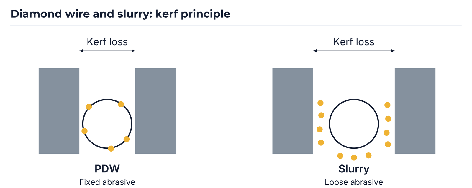
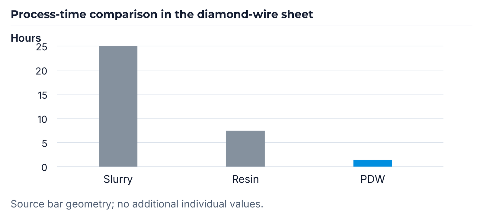
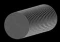
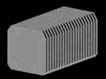
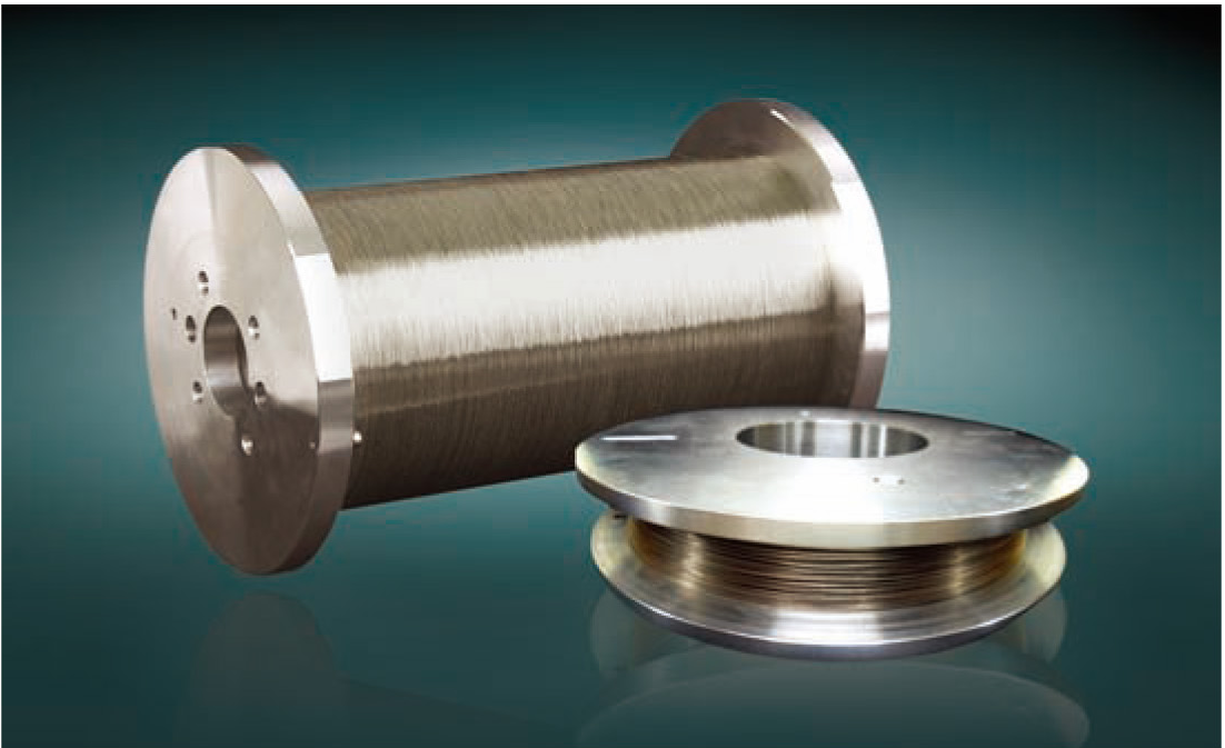
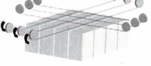
PDW combines narrow kerfs with strong cutting quality and throughput. Uniform diamond grit supports thin wafers, flatness and favourable warp, TTV and bow values. Diamond retention and usable wire life are designed for reliable cutting. The sources state 3~10 times faster cutting than their slurry process and a process without abrasive slurry. The comparison depends on material and process; “slurry-free” does not automatically mean machining without cooling.
Cropping covers single-crystal silicon and sapphire ingots. Squaring covers single-crystal silicon, polycrystalline jumbo ingots and sapphire ingots for cover-glass blocks. Wafering covers mono/poly silicon, sapphire and SiC. The silicon sheets mention 50 µm and 120 µm wire versions and application codes 300-D50 and 250-D50 for squaring and 90-D35 for slicing. The 90-D35 application code is not replaced by the different 90-D12 table item.
For sapphire, 2″, 4″ and 6″ and expansion to 8″ are described. Compared with resin-coated diamond wire, the sources describe improved thermal stability, longer life and shorter cutting time. The different table programmes are retained in full as separate versions.



Diamond wire: three complete programme versions
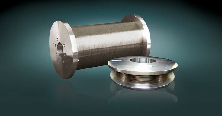
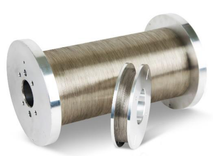
The programmes differ not only in additional thin wires but also in order codes, wire core, WBS and kerf loss. WBS means wire breaking strength. The core material is high-quality piano wire. Low, medium and high diamond concentrations and spool lengths of 5, 10, 20, 30, 50 and +100 km are described; customer-specific versions are available.
The nine-row programme contains 80-D10 and 250-D45, 300-D45 and 350-D45. For 350-D45, the source diameter column states 300; this differing source statement remains visible and is checked against the specification during selection. The expanded thirteen-row programme adds 50-D-9 and 60-D-10; the differing hyphen patterns remain part of the order designations.
| Application | Order code | Core-wire Ø [µm] | WBS [N] | Diamond size [µm] | Kerf loss [µm] |
|---|---|---|---|---|---|
| Mono-/poly-Si wafering | 70-D10 | 70 | 18 | 8~12 | 80~90 |
| Mono-/poly-Si wafering | 80-D12 | 80 | 21 | 8~16 | 90~100 |
| Mono-/poly-Si wafering | 90-D12 | 90 | 23 | 8~16 | 100~110 |
| Mono-/poly-Si wafering | 120-D15 | 120 | 40 | 10~20 | 140~145 |
| Sapphire-ingot wafering | 160-D35 | 160 | 65 | 30~40 | 220~240 |
| Sapphire-ingot wafering | 180-D35 | 180 | 85 | 30~40 | 235~255 |
| Sapphire-ingot wafering | 180-D45 | 180 | 85 | 40~50 | 245~255 |
| Si squaring / sapphire cropping | 200-D35 | 200 | 110 | 30~40 | 260~280 |
| Si squaring / sapphire cropping | 250-D35 | 250 | 180 | 30~40 | 310~330 |
| Si squaring / sapphire cropping | 250-D50 | 250 | 180 | 40~60 | 340~360 |
| Si squaring / sapphire cropping | 300-D50 | 300 | 240 | 40~60 | 390~410 |
| Application | Order code | Core-wire Ø [µm] | WBS [N] | Diamond size [µm] | Kerf loss [µm] |
|---|---|---|---|---|---|
| Mono-/poly-Si wafering | 60-D10 | 60 | 12 | 6~12 | 75~85 |
| Mono-/poly-Si wafering | 70-D10 | 70 | 16 | 8~12 | 85~95 |
| Mono-/poly-Si wafering | 80-D10 | 80 | 20 | 8~12 | 90~100 |
| Sapphire-ingot wafering | 160-D35 | 160 | 65 | 30~40 | 220~240 |
| Sapphire-ingot wafering | 180-D35 | 180 | 85 | 30~40 | 235~255 |
| Sapphire-ingot wafering | 180-D45 | 180 | 85 | 40~50 | 245~255 |
| Si squaring / sapphire cropping | 250-D45 | 250 | 180 | 40~50 | 345~355 |
| Si squaring / sapphire cropping | 300-D45 | 300 | 240 | 40~50 | 395~405 |
| Si squaring / sapphire cropping | 350-D45 | 300 | 320 | 40~50 | 445~455 |
| Application | Order code | Core-wire Ø [µm] | WBS [N] | Diamond size [µm] | Kerf loss [µm] |
|---|---|---|---|---|---|
| Mono-/poly-Si wafering | 50-D-9 | 50 | 10 | 5~10 | 60~70 |
| Mono-/poly-Si wafering | 60-D-10 | 60 | 12 | 6~12 | 70~80 |
| Mono-/poly-Si wafering | 70-D10 | 70 | 18 | 8~12 | 80~90 |
| Mono-/poly-Si wafering | 80-D12 | 80 | 21 | 8~16 | 90~100 |
| Mono-/poly-Si wafering | 90-D12 | 90 | 23 | 8~16 | 100~110 |
| Mono-/poly-Si wafering | 120-D15 | 120 | 40 | 10~20 | 140~145 |
| Sapphire-ingot wafering | 160-D35 | 160 | 65 | 30~40 | 220~240 |
| Sapphire-ingot wafering | 180-D35 | 180 | 85 | 30~40 | 235~255 |
| Sapphire-ingot wafering | 180-D45 | 180 | 85 | 40~50 | 245~255 |
| Si squaring / sapphire cropping | 200-D35 | 200 | 110 | 30~40 | 260~280 |
| Si squaring / sapphire cropping | 250-D35 | 250 | 180 | 30~40 | 310~330 |
| Si squaring / sapphire cropping | 250-D50 | 250 | 180 | 40~60 | 340~360 |
| Si squaring / sapphire cropping | 300-D50 | 300 | 240 | 40~60 | 390~410 |
Diamond-wire production, dressing and process control
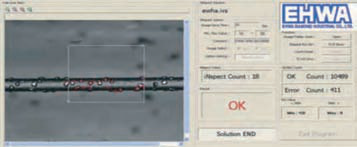
The production sequence starts with raw wire and pre-treatment. Strike electroplating and electroplating with Ni-coated diamond follow, then electroplating for retention, dressing, inspection and packaging. Real-time counting and inline inspection support process control.
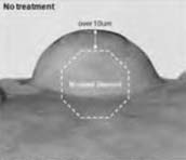
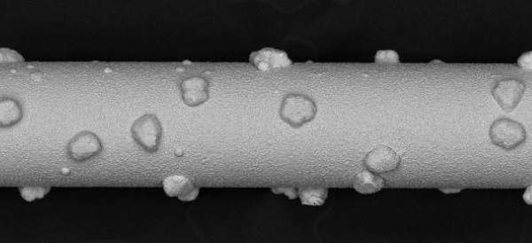
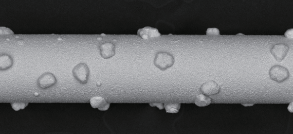
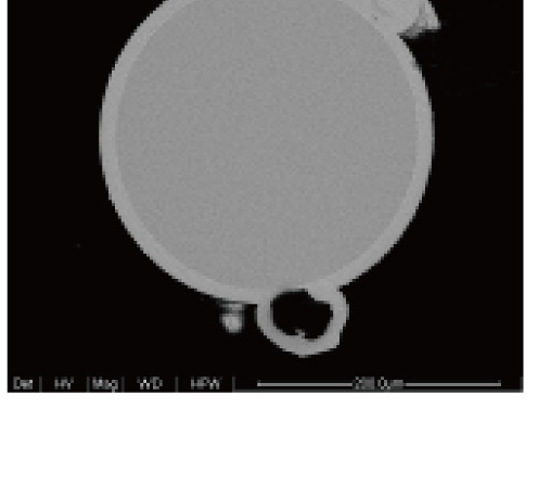
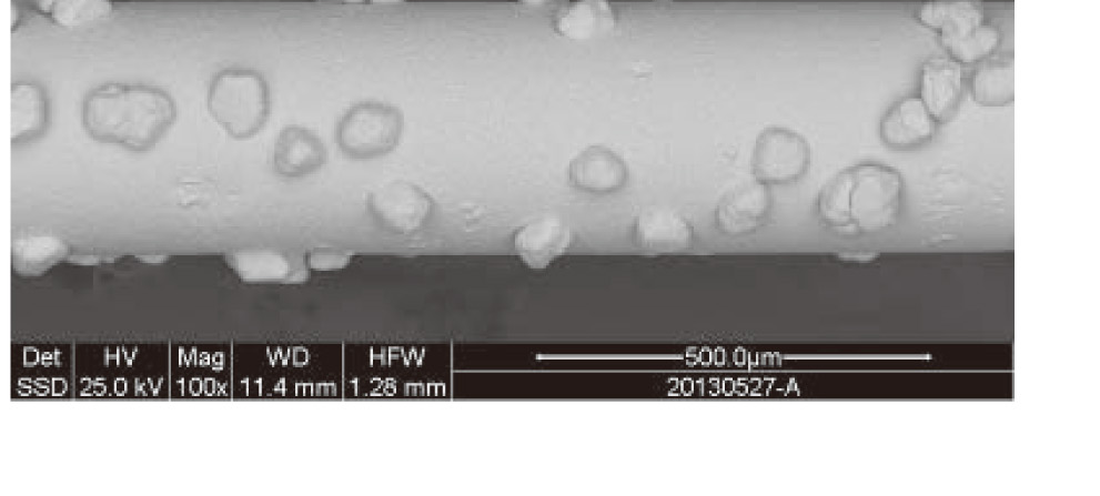
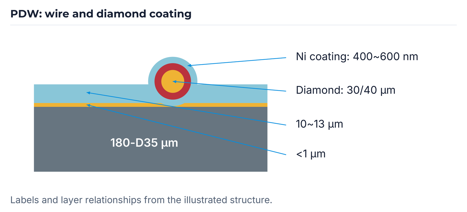
The structural illustration carries 180-D35 µm, a lower layer <1 µm, an upper layer 10~13 µm, diamond 30/40 µm and Ni coating 400~600 nm. These labels refer to the illustrated structure. The before/after dressing images show a 10 µm protrusion before dressing and the indicated material removal to prepare the diamond for cutting.
| Label | Source value |
|---|---|
| Wire designation | 180-D35 µm |
| Lower layer | <1 µm |
| Upper layer | 10~13 µm |
| Diamond | 30/40 µm |
| Ni coating | 400~600 nm |

Additional semiconductor machining: back grinding, dicing and CMP
The industry brochure extends the glass programme with silicon back grinding and LED/sapphire back grinding. Low edge chipping, die strength, high feed rates and thin wafers are design targets. For dicing and microblades it lists silicon, LT/LN, glass, ceramics and QFN, FBGA, CSP and MCP: fine cuts, low chipping, precision with thin blades, and high rotational speeds and feeds.
BSL CMP conditioners combine precision diamond placement and protrusion control with strong brazed attachment. Diamond selection and quality control support low defects and uniform wafer processing. CVD conditioners are designed for stable pad and wafer removal over longer use, low consumption and reduced maintenance time. The source describes a chemically stable contact solution intended to minimise metal contamination; this does not replace contamination qualification for each slurry/pad system.
| Version | Manufacturer | Listed machines |
|---|---|---|
| BSL | AMAT | Mirra / Reflexion |
| BSL | Ebara | F-Rex200/300 / EPO-222(H) |
| BSL | Lam | Auriga / CMP200/300 / Avantgaard 776(676) / Momentum / Teres |
| BSL | Strasbaugh | 6DS+SP / 6ED |
| CVD | AMAT | Reflexion LK / Mirra |
| CVD | Ebara | F-REX series |
| CVD | K.C.T. | Source lists no model |



Technical support and company background
Since 1975, EHWA has developed diamond tools and technical solutions with customers. Product quality, service and expertise are central. The industry brochure describes the aim of equipping customers with suitable products and technical information and supporting their manufacturing success. EHWA Europe is your contact for designing and coordinating your current application.
The following location photographs come from the 2016 brochure. They document the company background at that time: Osan HQ, Osan 2, Dongtan, Pyeongtaek, Seochun and Oksan; Shanghai, Weihai, Fujian and Indonesia; and branches in the USA, Japan, Thailand, Germany, India and Mexico. The historical photographs are not a current location directory.


Discuss your application with EHWA
Tell us your material and workpiece, glass or wafer thickness, machine and mounting, process stage and required edge or surface quality. For diamond wire, also provide the cutting operation, ingot size, wire core, concentration and required spool length. EHWA Europe supports suitable tool and process selection.
Documents and source mapping
The complete family edition is based on 38 distinct PDF documents with 96 physical pages. Q107 and Q108 are recorded as an identical duplicate in the manufacturer index and are used once. Identical pages are presented with all provenance retained; technical versions keep their own programmes and test details.
- Q006 · 2 pages
- Q007 · 1 page
- Q008 · 1 page
- Q009 · 2 pages
- Q010 · 1 page
- Q015 · 1 page
- Q020 · 1 page
- Q021 · 2 pages
- Q023 · 2 pages
- Q024 · 1 page
- Q027 · 1 page
- Q028 · 1 page
- Q029 · 2 pages
- Q031 · 1 page
- Q032 · 2 pages
- Q042 · 4 pages
- Q046 · 6 pages
- Q060 · 5 pages
- Q063 · 2 pages
- Q096 · 1 page
- Q097 · 1 page
- Q098 · 1 page
- Q099 · 2 pages
- Q100 · 1 page
- Q104 · 1 page
- Q105 · 5 pages
- Q106 · 6 pages
- Q107 / Q108 · 2 pages
- Q113 · 1 page
- Q114 · 1 page
- Q123 · 5 pages
- Q124 · 5 pages
- Q125 · 6 pages
- Q126 · 2 pages
- Q208 · 5 pages
- Q209 · 6 pages
- Q210 · 2 pages
- Q231 · 5 pages
Questions about tool selection
Which diamond tools are suitable for display glass?
The EHWA range includes metal-bond and electroplated tools for edge grinding, scribing wheels, and polyurethane and cerium-oxide tools for edge polishing. Selection depends on glass type, thickness, machining stage and required edge quality. The tables distinguish the individual tool designs and programme versions.
Which sapphire-wafer processes does EHWA support?
The programme describes metal-bond rough-grinding tools, vitrified fine-grinding tools, edge-grinding wheels, iron-resin lapping plates and precision diamond wire for sapphire. Application examples distinguish wafer sizes, WAX and TAPE mounting, and their process conditions.
How is precision diamond wire used in solar and wafer production?
Precision diamond wire is used for cropping, squaring and wafering: cutting ingots to length, producing block forms and slicing thin wafers. The EHWA programme includes applications for mono- and polycrystalline silicon, sapphire and SiC. Order code, wire core, diamond size, breaking strength and kerf loss are listed in separate programme versions.
What information does EHWA need for tool selection?
Provide the material and workpiece, glass or wafer thickness, machine and mounting, machining stage, and required surface or edge result. For diamond wire, also specify the cutting operation, ingot size, wire core, concentration and spool length. The enquiry link in each chapter carries the relevant document reference.