Wearless and Wear Parts for workpiece support, bearing manufacturing and measuring applications
EHWA DIAMOND - since 1975
Contact surfaces with a defined function
EHWA presents wear parts that support, guide or contact workpieces for measurement. The Wearless and Wear Parts families comprise backing plates, V-blocks, sliding shoes, dead centres, special gauges and guide blades. The programme combines application-specific geometries with wear-resistant contact materials.
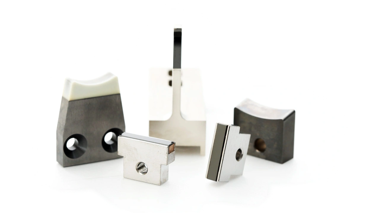
Selection considers contact position, workpiece, machine and surface requirements. The illustrated forms and actual product photographs show different designs; the component drawing defines the specific function and mounting. Wearless remains the product name.
Material and contact surface
The Wear Parts document identifies four material families: polycrystalline diamond (PCD), PCBN, tungsten carbide and ceramics. Material selection follows the actual contact task.
| Material family | Relationship described in the document |
|---|---|
| PCD | Wear resistance for longer useful life; polished contact surfaces to reduce friction |
| PCBN | Identified as a material family for wear parts; actual design matched to the application |
| Tungsten carbide | Identified as a material family for wear parts; actual design matched to the application |
| Ceramics | Chemical resistance as a feature supporting reduced chemical wear and surface scratching |
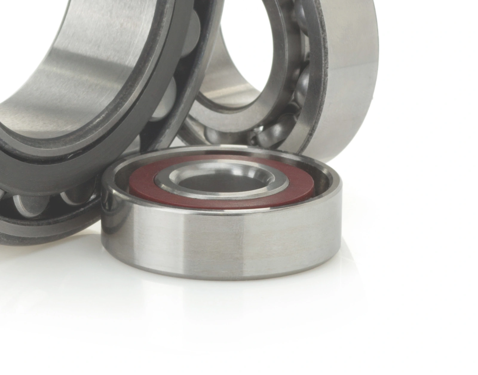
EHWA describes PCD wear resistance as a basis for longer useful tool life. A polished PCD contact surface can reduce friction. The document gives a minimum Ra value of 0.02 without specifying a unit. Target roughness, unit and measurement conditions are defined together for the actual design.
For ceramics, EHWA describes chemical resistance and its benefit to the contact surface and workpiece finish. The appropriate ceramic design is matched to the material pair, loading and process media. Precise customised geometries are available on request.


Applications and component families
| Application | Components or tasks listed in the programme |
|---|---|
| Centreless grinding machines | Support and guide blades for centreless grinding |
| Cylindrical grinding machines | Support and contact components matched to the machine and workpiece |
| Measuring probes and metrology | Gauges and measuring contacts |
| Bearing manufacturing | Support and contact components matched to component geometry |
| Other machines | Customised contact geometries |
The Wear Parts sheet lists Centerless blades, Sliding shoes & V-blocks as work-rest parts, Backing plates for bearing manufacturing and Gauges as measuring probes. The Wearless illustrations supplement these families with dead centres and further backing plate, V-block, shoe, gauge and guide blade designs.
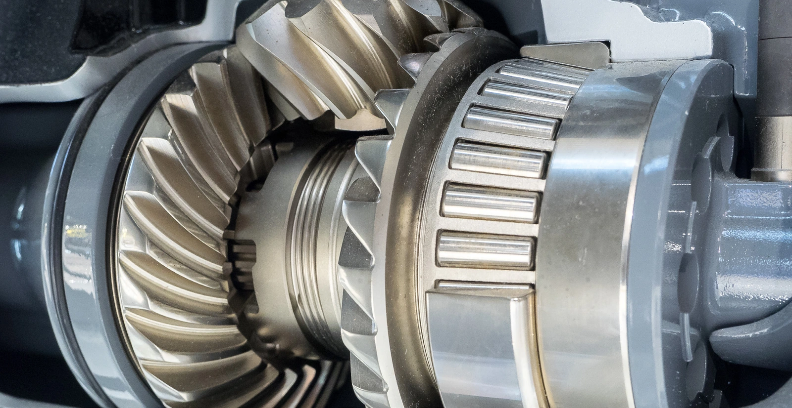

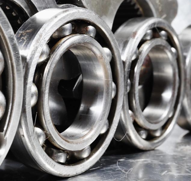

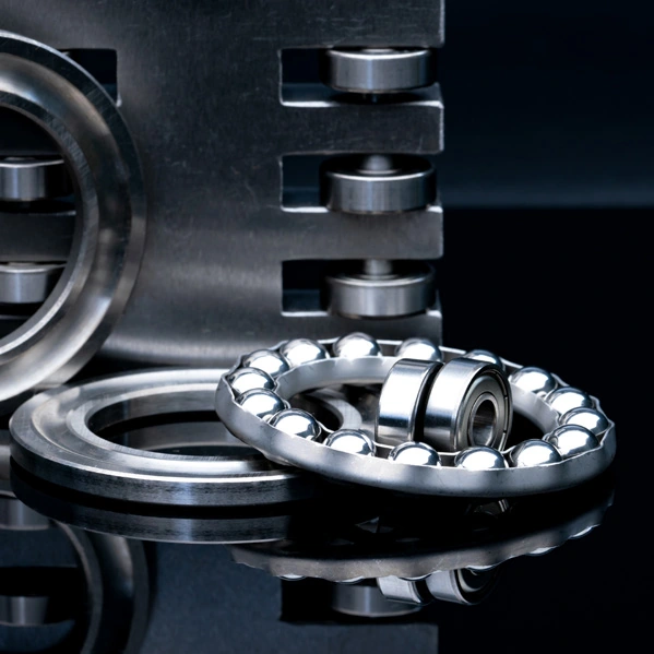
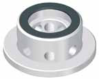
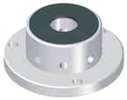
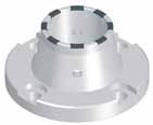
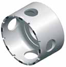
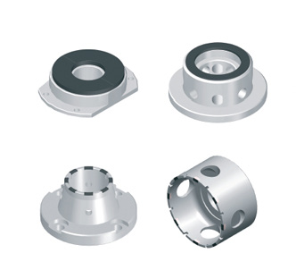
Bearing backing plates: five Wearless designs
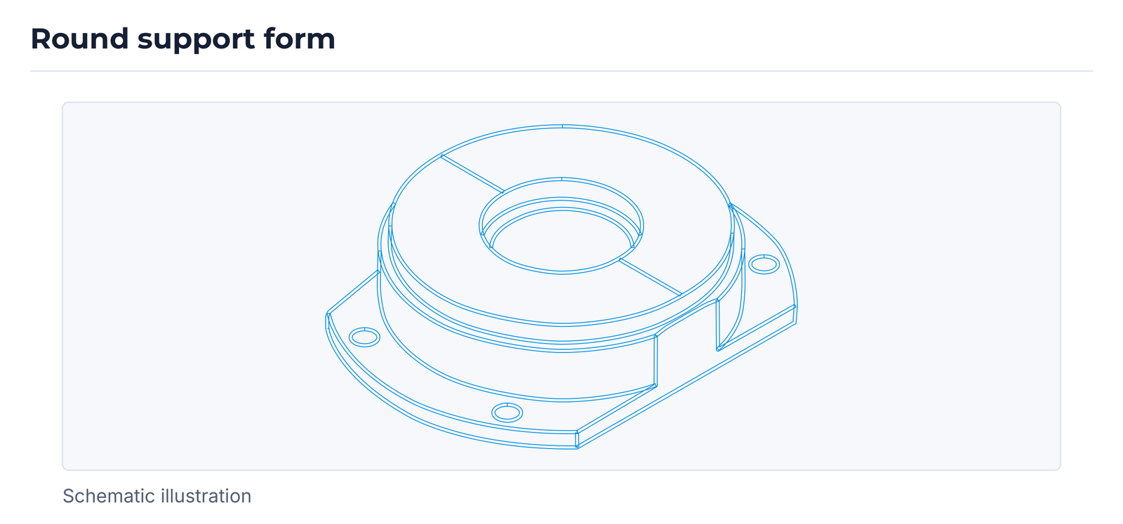
The Wearless Bearing backing plate group shows five backing plate forms. These include round contact faces, ring-shaped contact areas and segmented contact surfaces. Holes, mounting faces and contact area positions remain visible in the illustrations. The design is matched to the relevant bearing processing task.
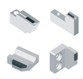
V-blocks: seven Wearless designs
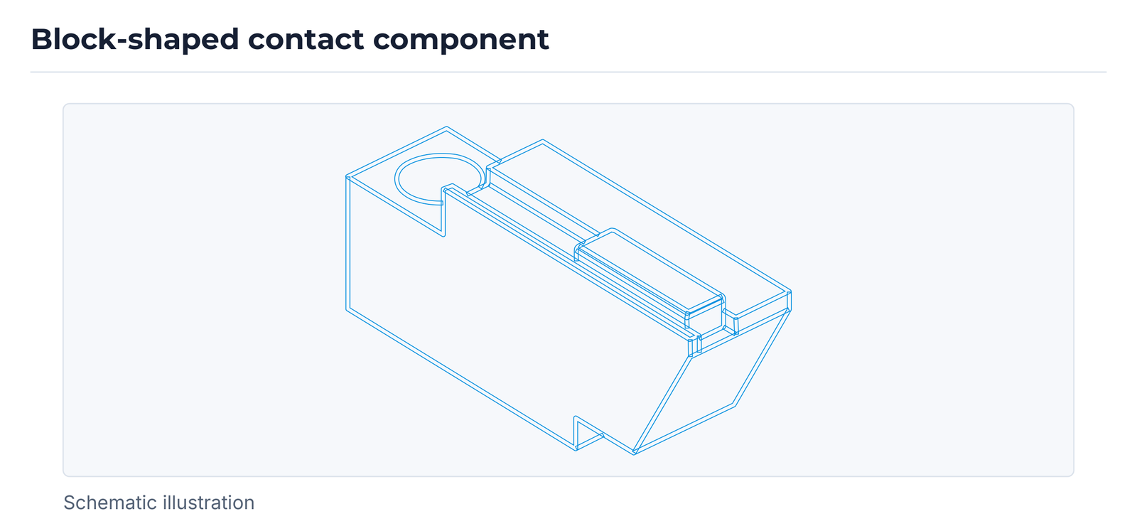
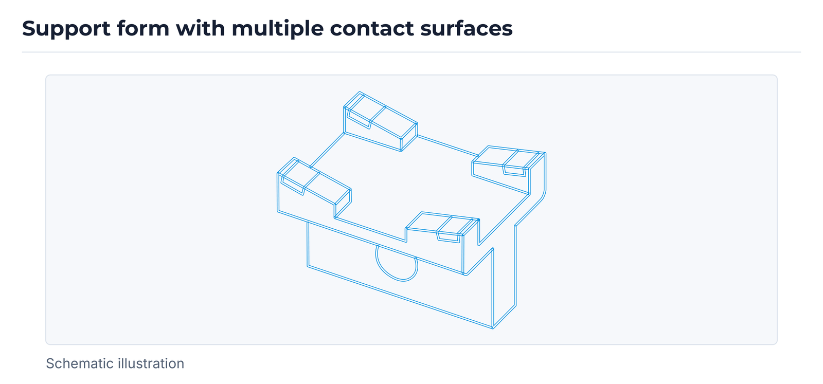
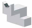
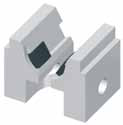
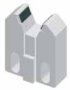
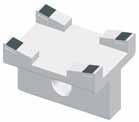
The V-block group shows different block-shaped workpiece supports. The illustrations include individual and opposing contact surfaces, fitted contact pieces and different mounting arrangements. Geometry is matched to the workpiece and machine mounting.


Sliding shoes: five Wearless designs
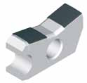
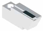
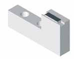
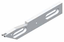
The Shoe group contains five design images with different contact positions. These include elongated forms, compact block forms and a narrow elongated design with mounting openings. The contact surface is matched to the actual workpiece surface being supported or guided.
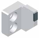
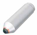
Dead centre
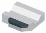
The Wearless document shows a fixed centre under the name Dead center. The illustrated contact area is at the tip. Mounting, workpiece contact and material design are defined for the specific machine; the illustration contains no additional installation dimensions.
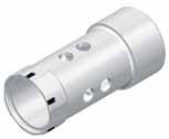
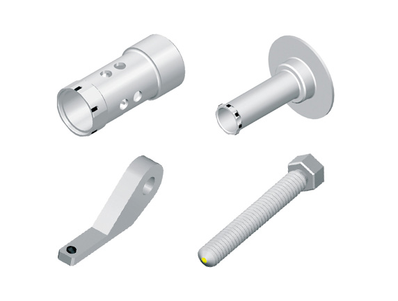
Special gauges and measuring contacts
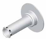
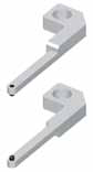
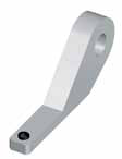
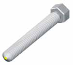
The Special gauges group shows five design images: cylindrical and flanged forms, elongated probing forms, an angled form and a threaded design with a measuring contact. Measurement function is matched to the drawing, contact position and required accuracy.
Guide blades and work-rest blades
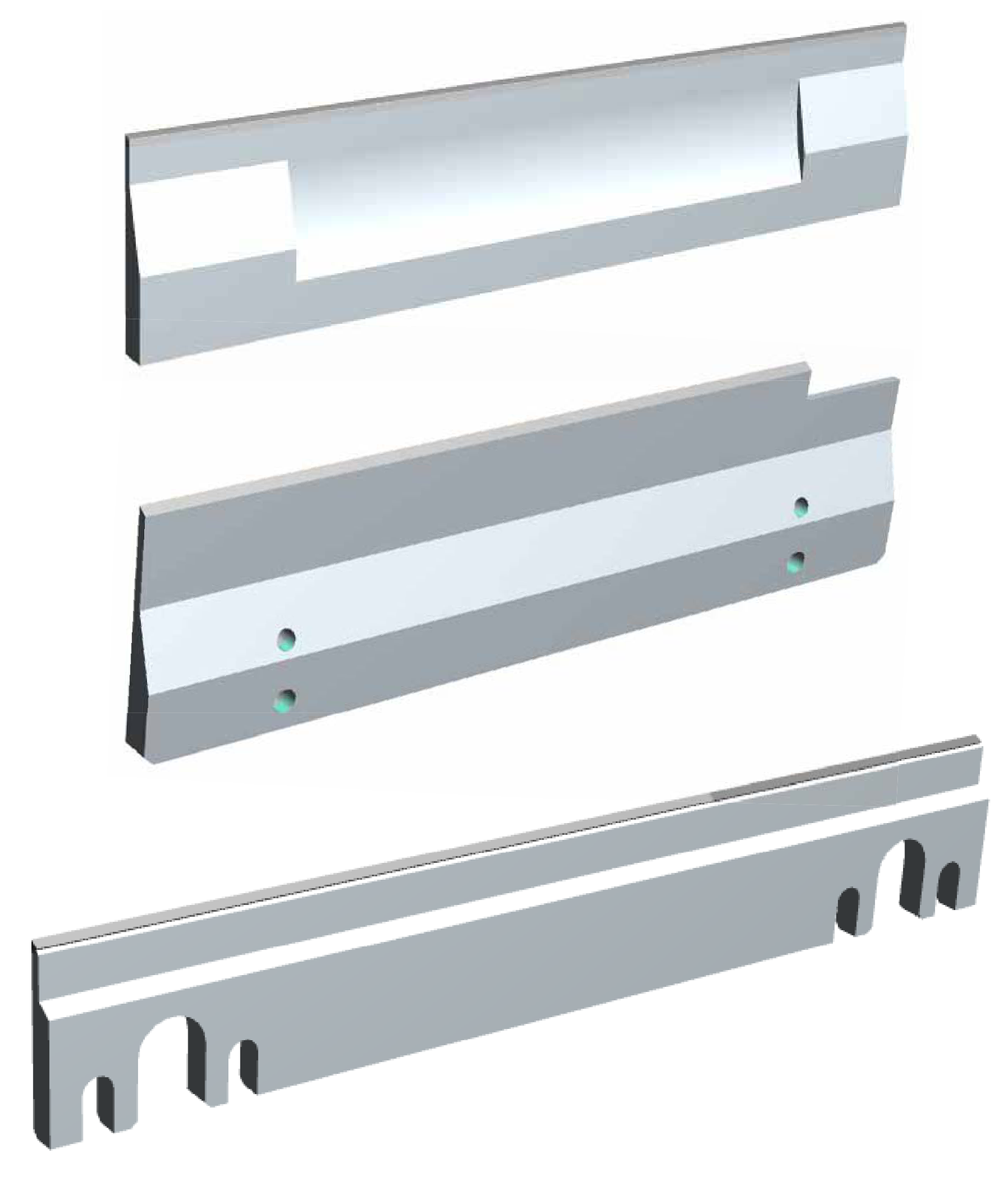
The Wearless Guide blade group shows three elongated blade forms with different contact strips and mounting features. All three illustrations are retained. Corresponding blade forms are presented in the Wear Parts overview as Centerless blades for centreless grinding.
Further designs from Wear Parts
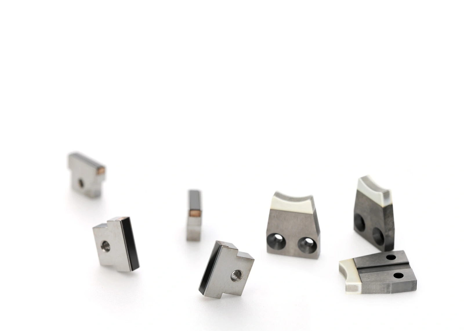
The overview shows round and block-shaped support/contact components, gauges and work-rest blades. Basic forms can fulfil different contact tasks depending on the design. The final mapping to a sliding shoe, V-block or backing plate therefore follows the specific drawing and application.
Discuss your contact task
Provide the component drawing, workpiece material, machine, mounting and contact position. Add loading, process media, required surface parameters and desired useful life. For replacement parts, existing mounting dimensions, contact marks and the current wear pattern support the discussion.
A suitable design combines wear-resistant contact surfaces with geometry matched to the machine. Comparison considers dimensional change of the wear part, workpiece surface condition and useful life together.
EHWA Europe: info@ehwadia.de · +49 6173 997780
Editorial edition: 13 October 2026. Technical basis: the complete EHWA Wearless document, four pages, and Wear Parts document, two pages. Wear Parts bears the printing note 06/2024.