Application · Automotive

Crankshaft Grinding

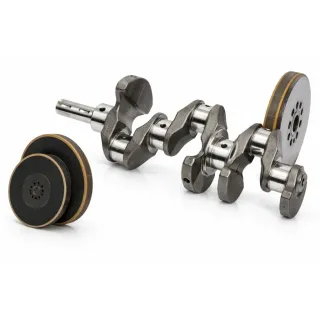
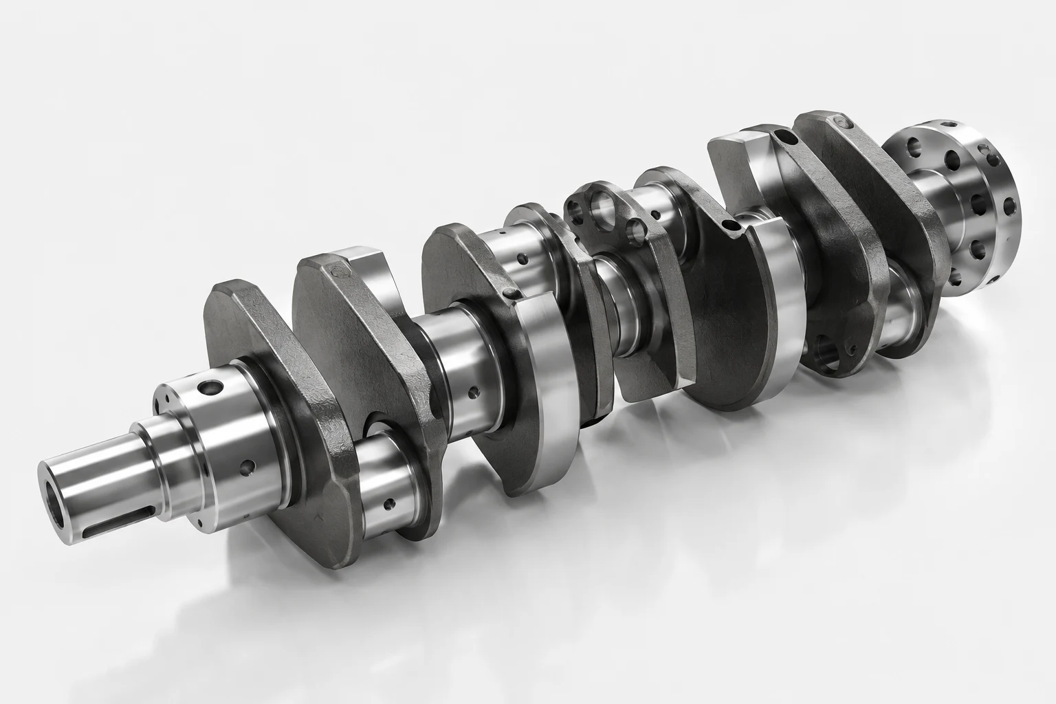
The crankshaft converts the energy generated in the combustion process into rotational motion. High speeds and torques subject the component to considerable mechanical and thermal loads.

VEWN CeramicB76 – B151Cylindrical · Profile
Kurbelwelle in der Schleifbearbeitung

Select the surface you want to grind

Click a surface of the crankshaft to see the machining process and the matching EHWA tool solution.

Main bearing journal

Bearing seats on the axis of rotation

Standard grinding wheel shape 1A1

The main bearing journals guide the crankshaft in the crankcase. They lie on the axis of rotation and are plunge-ground to size and surface quality.

Recommended solution

Cylindrical grinding · plunge method

Tool type
Cylindrical grinding wheel
Shape
1A1
Abrasive
CBN
Grit size
B76 – B151
Request a design
Technical details
Process
Cylindrical grinding · plunge method
Bond
VEWN – EHWA ceramic bond
Grit size
B76 – B151
Dimensions
Ø up to 650 mm
Design
Customer-specific, according to machine and process

Pin journal

Eccentrically offset connecting rod bearings

Standard grinding wheel shape 1A1

The pin journals carry the connecting rods. They run eccentrically to the axis of rotation – the grinding wheel follows the stroke movement while the shaft rotates about its main axis.

Recommended solution

Cylindrical grinding · eccentric

Tool type
Cylindrical grinding wheel
Shape
1A1
Abrasive
CBN
Grit size
B76 – B151
Request a design
Technical details
Process
Cylindrical grinding · eccentric
Bond
VEWN – EHWA ceramic bond
Grit size
B76 – B151
Dimensions
Ø up to 650 mm
Design
Customer-specific, according to machine and process

Fillet radius

Transition from journal to crank web

Standard grinding wheel shape 1A1

The radius between journal and web largely determines the fatigue strength of the shaft. It is ground with a profiled wheel in the same setup as the journal.

Recommended solution

Profile grinding

Tool type
Profile grinding wheel
Shape
1A1 profiled
Abrasive
CBN
Grit size
B76 – B151
Request a design
Technical details
Process
Profile grinding
Bond
VEWN – EHWA ceramic bond
Grit size
B76 – B151
Dimensions
Ø up to 650 mm
Design
Customer-specific, according to machine and process

Shaft journal

Cylindrical seat at the front shaft end

Standard grinding wheel shape 1A1

The front shaft journal accommodates the seal and drive elements. Dimensional accuracy and surface quality determine the sealing performance in operation.

Recommended solution

Cylindrical grinding

Tool type
Cylindrical grinding wheel
Shape
1A1
Abrasive
CBN
Grit size
B76 – B151
Request a design
Technical details
Process
Cylindrical grinding
Bond
VEWN – EHWA ceramic bond
Grit size
B76 – B151
Dimensions
Ø up to 650 mm
Design
Customer-specific, according to machine and process

Flange face

Face at the output end

Standard grinding wheel shape 6A2

The flange face carries the flywheel. Flatness and squareness to the axis of rotation determine the concentricity of the entire drivetrain.

Recommended solution

Surface grinding

Shape
6A2 cup wheel
Abrasive
CBN
Grit size
B76 – B151
Request a design
Technical details
Process
Surface grinding
Bond
VEWN – EHWA ceramic bond
Grit size
B76 – B151
Dimensions
Ø up to 650 mm
Design
Customer-specific, according to machine and process
More surfaces

Process


Crankshafts have a very hard, wear-resistant surface combined with a tough core and are made from high-alloy quenched-and-tempered steels or special cast materials.

EHWA has developed a ceramic bond for this purpose that enables efficient, tool-life-optimized grinding of crankshafts.

What the process gains


Longer dressing intervals

Higher tool life and reduced downtime

Consistent surface quality

Reproducible quality over the entire tool life

Reduced thermal load

Lower risk of grinding burn and microstructural changes

Recommended tools


Tool program for Crankshaft Grinding
Product types Cylindrical and profile grinding wheels
Bond VEWN – EHWA ceramic bond
Grit sizes B76 – B151

Process example


B151 L200 VEWN

Cylindrical grinding of cast alloy (FCD)

Goal: Increase grinding wheel tool life while maintaining stable process control

up to 20 %
Higher tool life
Process parameters
Material Cast alloy (FCD)
Workpiece diameter 60 mm
Grinding wheel diameter Ø 650 mm
Peripheral speed 80 m/s
Feed rate 0.05 mm/s
Stock removal 1.2 mm/D

Result

  • Fewer dressing cycles, higher machine availability
  • More stable process control, consistent component quality
  • Lower cost per part

Figures from an approved customer process. Tools are always engineered around the machine, workpiece, and process of the individual case – these figures are evidence, not a guarantee.