Coring, focus-ring contours, and edge and notch grinding
EHWA DIAMOND – since 1975
From a ring blank to the finished contour
EHWA offers coordinated tool designs for coring, rough and fine grinding of focus rings, and wafer edge and notch machining. Different bonds and tool geometries combine removal performance, useful life and dimensional accuracy with the machining task.
Si means silicon; SiC means silicon carbide. Material and manufacturing route are part of tool selection. The programme covers both materials, while the machining examples below explicitly distinguish Si focus rings from sintered or CVD SiC components.
Core wheels: produce a ring structure from Si or SiC
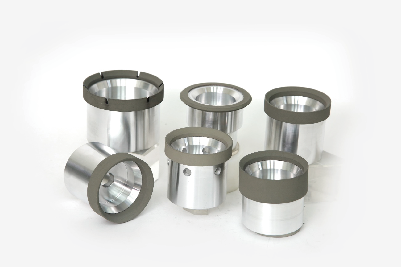
Core wheels remove the centre of a Si or SiC plate to create a ring-shaped structure. EHWA manufactures different tool shapes and material designs for the machining task.
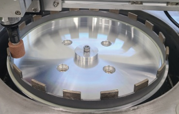
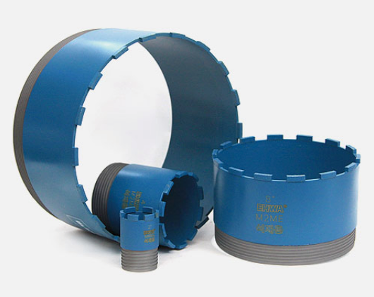
Characteristics and advantages
- Different tool shapes for different processing purposes.
- Electroplated, sintered or brazed cutting tips, matched to customer requirements and the target processing performance.
- Field-proven, consistent processing quality.
- Selection of geometry and material design according to useful life, grinding ability and dimensional accuracy.
Tool mounting, plate thickness and the required ring geometry provide the basis for the specific design.
Electroplated tools for rough machining of Si focus rings
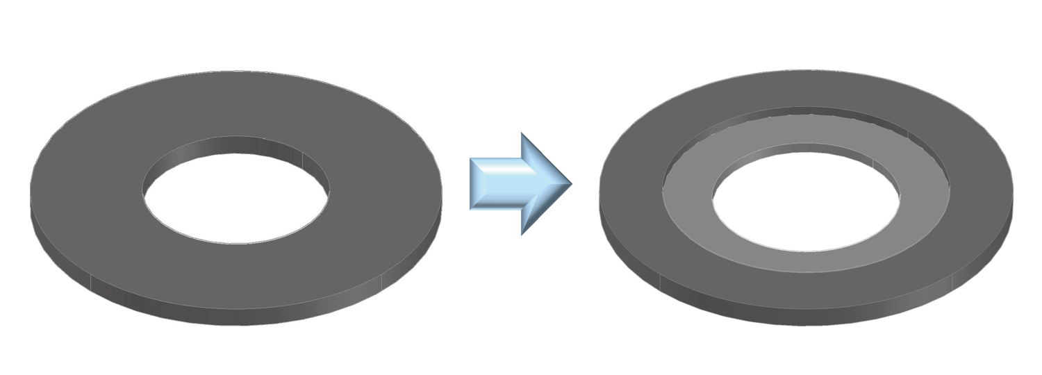
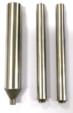
The illustrated electroplated tools machine different Si focus-ring contours, including the outside diameter, internal contour and tapered regions. The shape example shows the transition from a plain ring to a profiled ring contour.

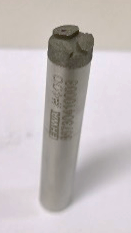
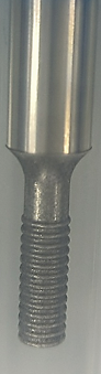
EHWA can manufacture different tool designs for chamfers, holes, internal contours and the tapping operation named in the source document.
| Illustrated tool group | Machining task |
|---|---|
| Chamfering Wheel | Chamfer machining |
| Hole Grinding | Hole grinding |
| Arbor Grinding | Internal-contour machining |
| Tap Grinding | Thread machining; specific contour according to the component drawing |
Chamfering tools

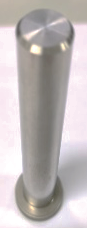
Hole grinding
Internal contour and Tap Grinding
Vitrified and resin-bond tools for fine machining
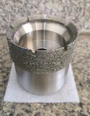
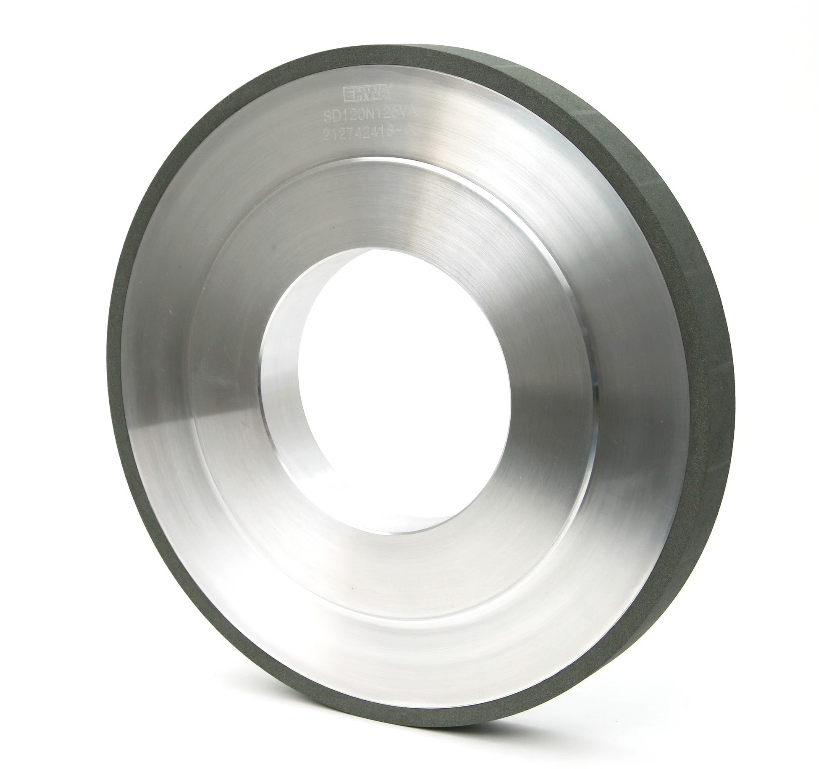
Fine machining covers Si and SiC focus rings with outside and inside contours and tapered regions. EHWA lists vitrified and resin-bond grinding wheels for these tasks. The process diagrams explicitly show vitrified wheels; the specific bond and grit are selected for the material, contour and surface target.
Si focus ring: cross-section and machining directions
The cross-section diagram marks the ground surfaces in red. Tool positions and arrows show grinding directions along the Z axis and combined X- and Z-axis directions. Different ring faces and contours can therefore be addressed.

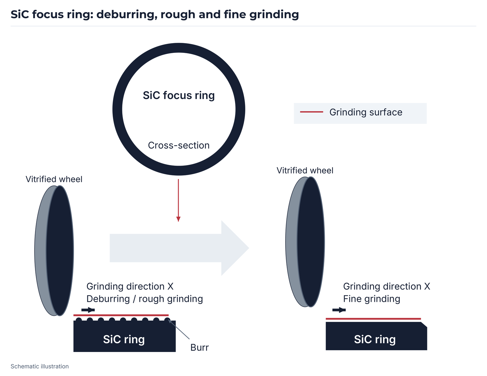
SiC focus ring: deburring, rough grinding and fine grinding
The SiC diagram first shows burr removal and rough grinding, followed by fine grinding. Both stages indicate grinding along the X axis. The red line marks the grinding surface; the burr is identified separately in the first state.
Documented SiC machining example
The complete specification below describes the illustrated example using sintered or CVD SiC. It provides a starting point for matching the wheel, machine and required surface.
| Parameter | Specification in the machining example |
|---|---|
| Customer | Not named |
| Wheel designation | VD-14A1_305D-35T-5X-30U-127H |
| Machine | Rotary surface grinding machine |
| Wheel specification | D120N125VD, D600N125VA, D800N125VA |
| Wheel speed | 50–70 m/s |
| Workpiece | Sintered SiC or CVD SiC |
| Coolant | Emulsion |
| Required roughness after grinding | Ra 0.10–0.05 |
| Table rotational speed | Not specified |
| Feed rate | Rough machining: 1500 mm/min |
| Dresser | SiC #80 |
| Dressing system | Not specified |
| Dressing amount | Not specified |
| Dressing interval | 3–5 |
The example gives no unit for Ra or reference basis for the dressing interval. These details are agreed together with the required surface and actual machine cycle.
Si/SiC wafer edges and notches
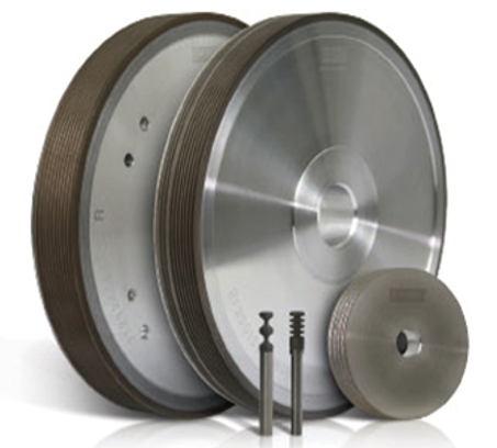
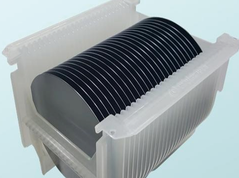
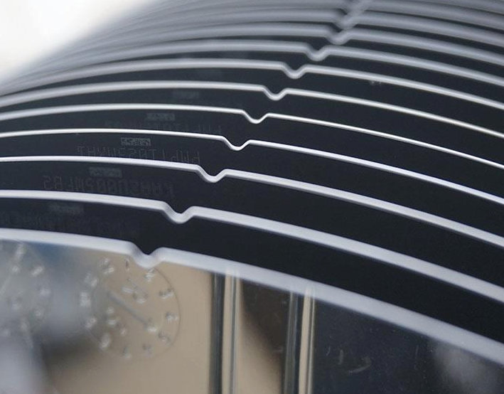
EHWA offers profiled grinding wheels and small notch tools for machining Si and SiC wafers. Different groove forms can be designed for the required edge contour.
Advantages of profiled designs
- Different groove forms to suit the requirement.
- Uniform chamfer width supported by a rigid tool design.
- Good groove-form retention during machining.
- Multiple rough- and fine-grinding stages with a tool designed for that purpose.
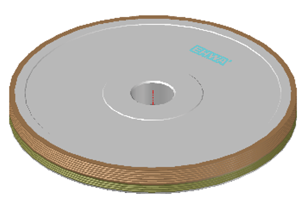
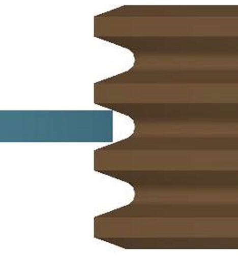
Wheel shape and groove contact
The technical illustration shows the profiled grinding wheel and a contact position within a groove. Profile, chamfer width and tool rigidity are specified together for the wafer edge.
| Application | Diameter designation | Grit range |
|---|---|---|
| Edge grinding | 100D–300D | #400–#3000 |
| Notch grinding | 3.2D–4.2D | #400–#3000 |
The original provides the D designations without a separate dimensional definition; tool diameter and mounting are confirmed for the machine.
Notch grinding: rough and fine stages
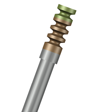
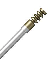
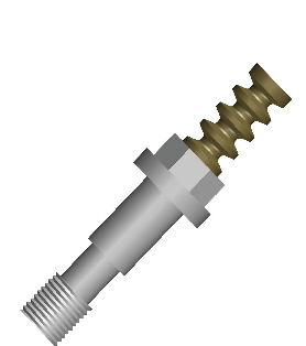
The document shows three tool forms: a combined design for the first and second machining stages, a design for the first rough stage and a design for the second fine stage.
Combined first and second stages
First stage: rough machining
Second stage: fine machining
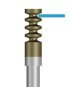
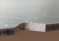
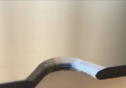
The before/after photographs illustrate the machined notch edge.
Process example for 12-inch wafers
The diagram combines a metal-bond wheel for rough grinding with a resin-bond wheel for fine grinding. It also shows profile truing using a SiC truer.

| Component in the diagram | Illustrated relationship |
|---|---|
| Metal-bond wheel | Rough grinding, #800 |
| Truing region of the metal-bond wheel | Profiling the SiC truer, #600 |
| Resin-bond wheel | Fine grinding, #2500 |
| Si wafer | On a mount between the rough and fine stages |
| SiC truer | On a mount; SiC profile truing and resin-wheel truing |
The #800, #600 and #2500 shown in the sequence belong to this process example. The accompanying #400–#3000 designations describe the wider tool range for edge and notch grinding.
Design your Si/SiC machining process together
Useful starting information includes the component drawing, Si or SiC material grade, machine and tool mounting. For focus rings, outside and inside contours, tapered surfaces, plate thickness and the surface target are particularly helpful. For wafer edges and notches, add wafer size, edge profile, required chamfer width and existing rough/fine stages.
Current specifications, feed rates, coolants and dressing cycles support the discussion. Together, the tool design can be matched to dimensional accuracy, removal performance and useful life.
EHWA Europe: info@ehwadia.de · +49 6173 997780
Editorial edition: 13 October 2026. Technical basis: the complete EHWA documents Si_SiC PARTS (one page) and Si-Parts_2026 (four pages).