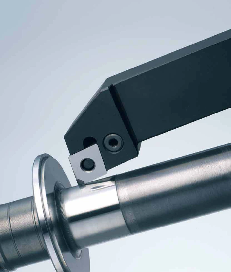
The process defines the tool task
Turning, boring, grooving, parting and milling produce different surfaces and chip conditions. EHWA describes inserts, holders and tool bodies with cutting materials and geometries adapted to the application. The process chapters help assign a machining task to the appropriate tool family.
Workpiece material and condition are part of selection. PCD is described for suitable non-ferrous and non-metallic materials, and PCBN for suitable ferrous materials such as hardened steel and cast iron. Selection by process alone is therefore insufficient.
Tool families in the process
| Process | Tool solution described | Important information |
|---|---|---|
| Turning | PCD and PCBN inserts with suitable holders | Surface, radius and interruption |
| Boring | Tools with steel or carbide bodies | Bore dimensions, overhang and mounting |
| Grooving and parting | PCD, PCBN or carbide tools | Groove width, depth and clamping conditions |
| Milling | Cutter bodies and inserts selected for the application | Material, engagement and surface objective |
| Aluminium alloy face milling | XF face cutters for roughing and finishing | Diameter, machine mounting and design |
Connect quality and useful tool life
The turning documents name removal performance, wear resistance, surface quality and tolerance control as objectives. Boring focuses on precise bores and suitable tool bodies. Grooving connects cutting material and tool stability with the actual groove task.
Milling documentation describes different cutting material grades and the possibility of resharpening and retipping. This can extend the useful life of a suitable tool. The possibility is checked for the actual tool design and does not apply automatically to every insert.
When comparing an existing process, achieved surface finish, dimensional deviations, wear pattern and machining time matter. These details help distinguish direct tool replacement from a change in geometry or process.
Catalogue example: XF face milling cutter
The XF data sheet shows the type XF 10050-16R (L) with a cutter diameter of 100 mm, a mounting bore of 31.75 mm and 8 teeth. The separate "Maximum Cutting Condition" table gives 11,000 min⁻¹ and a 3 mm depth of cut for Ø 100 mm.
These values belong to the XF design shown. The maxima are not cutting data that can be freely combined for other cutters or machines. Mounting, permissible tool speed, workpiece material and engagement are assessed together for your application. Drawing and item designation remain essential to selection.
Your technical enquiry
Send a drawing, material designation, machine and mounting details, and the intended result. For existing processes, the current tool specification, machining data and a description of the wear pattern help. Mention the topic and relevant catalogue page. We discuss the tool design and next steps with you.
EHWA Europe GmbH
Sources and complete catalogues
- Turning, PDF pages 2; HQ source.
- Milling, PDF pages 2; HQ source.
- Boring, PDF pages 2; HQ source.
- Grooving / Parting, PDF pages 2; HQ source.
- Tool Materials, PDF pages 2, 4-5; HQ source.
- XF Face Milling Cutters for Al Alloys, PDF pages 2; HQ source.
This thematic overview is a compact introduction to these applications. The linked original catalogues contain further designs, tables and technical information.